1
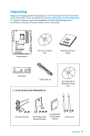
Product Information
Configurable NAT Router
Catalog Number 1783-NATR
ATTENTION: Read this document and the documents listed in the Additional Resources section about installation, configuration and operation of this equipment before you install, configure, operate or maintain this product. Users are
required to familiarize themselves with installation and wiring instructions in addition to requirements of all applicable codes, laws, and standards.
Activities including installation, adjustments, putting into service, use, assembly, disassembly, and maintenance are required to be carried out by suitably trained personnel in accordance with applicable code of practice.
If this equipment is used in a manner not specified by the manufacturer, the protection provided by the equipment may be impaired.
注意:在安装、配置、操作和维护本产品前,请阅读本文档以及 “ 其他资源 ” 部分列出的有关设备安装、配置和操作的相应文档。除了所有适用规范、法律和标准
的相关要求之外,用户还必须熟悉安装和接线说明。
安装、调整、投运、使用、组装、拆卸和维护等各项操作必须由经过适当训练的专业人员按照适用的操作规范实施。
如果未按照制造商指定的方式使用该设备,则可能会损害设备提供的保护。
ATENCIÓN: Antes de instalar, configurar, poner en funcionamiento o realizar el mantenimiento de este producto, lea este documento y los documentos listados en la sección Recursos adicionales acerca de la instalación, configuración y
operación de este equipo. Los usuarios deben familiarizarse con las instrucciones de instalación y cableado y con los requisitos de todos los códigos, leyes y estándares vigentes.
El personal debidamente capacitado debe realizar las actividades relacionadas a la instalación, ajustes, puesta en servicio, uso, ensamblaje, desensamblaje y mantenimiento de conformidad con el código de práctica aplicable.
Si este equipo se usa de una manera no especificada por el fabricante, la protección provista por el equipo puede resultar afectada.
ATENÇÃO: Leia este e os demais documentos sobre instalação, configuração e operação do equipamento que estão na seção Recursos adicionais antes de instalar, configurar, operar ou manter este produto. Os usuários devem se familiarizar
com as instruções de instalação e fiação além das especificações para todos os códigos, leis e normas aplicáveis.
É necessário que as atividades, incluindo instalação, ajustes, colocação em serviço, utilização, montagem, desmontagem e manutenção sejam realizadas por pessoal qualificado e especializado, de acordo com o código de prática aplicável.
Caso este equipamento seja utilizado de maneira não estabelecida pelo fabricante, a proteção fornecida pelo equipamento pode ficar prejudicada.
ВНИМАНИЕ: Перед тем как устанавливать, настраивать, эксплуатировать или обслуживать данное оборудование, прочитайте этот документ и документы, перечисленные в разделе «Дополнительные ресурсы». В этих
документах изложены сведения об установке, настройке и эксплуатации данного оборудования. Пользователи обязаны ознакомиться с инструкциями по установке и прокладке соединений, а также с требованиями всех
применимых норм, законов и стандартов.
Все действия, включая установку, наладку, ввод в эксплуатацию, использование, сборку, разборку и техническое обслуживание, должны выполняться обученным персоналом в соответствии с применимыми нормами и
правилами.
Если оборудование используется не предусмотренным производителем образом, защита оборудования может быть нарушена.
注意 : 本製品を設置、構成、稼動または保守する前に、本書および本機器の設置、設定、操作についての参考資料の該当箇所に記載されている文書に目を通して
ください。ユーザは、すべての該当する条例、法律、規格の要件に加えて、設置および配線の手順に習熟している必要があります。
設置調整、運転の開始、使用、組立て、解体、保守を含む諸作業は、該当する実施規則に従って訓練を受けた適切な作業員が実行する必要があります。
本機器が製造メーカにより指定されていない方法で使用されている場合、機器により提供されている保護が損なわれる恐れがあります。
ACHTUNG: Lesen Sie dieses Dokument und die im Abschnitt „Literaturverweise“ genannten Dokumente zur Installation, Konfiguration und Bedienung dieser Ausrüstung sorgfältig durch, bevor Sie dieses Produkt installieren, konfigurieren,
bedienen oder instandsetzen. Benutzer müssen sich mit den Anweisungen zur Installation und Verdrahtung vertraut machen und müssen die Anforderungen aller geltenden Vorschriften, Gesetze und Normen kennen.
Aktivitäten wie Installation, Einstellung, Inbetriebnahme, Verwendung, Montage, Demontage und Instandsetzung müssen durch ausreichend geschultes Personal in Übereinstimmung mit den geltenden Durchführungsvorschriften
ausgeführt werden.
Wenn diese Ausrüstung in einer Weise verwendet wird, die nicht vom Hersteller angegeben wurde, kann der von der Ausrüstung bereitgestellte Schutz beeinträchtigt sein..
ATTENTION : Lisez ce document et les documents listés dans la section Ressources complémentaires relatifs à l’installation, la configuration et le fonctionnement de cet équipement avant d’installer, configurer, utiliser ou entretenir ce
produit. Les utilisateurs doivent se familiariser avec les instructions d’installation et de câblage en plus des exigences relatives aux codes, lois et normes en vigueur.
Les activités relatives à l’installation, le réglage, la mise en service, l’utilisation, l’assemblage, le démontage et l’entretien doivent être réalisées par des personnes formées selon le code de pratique en vigueur.
Si cet équipement est utilisé d’une façon qui n’a pas été définie par le fabricant, la protection fournie par l’équipement peut être compromise.
주의: 본 제품 설치, 설정, 작동 또는 유지 보수하기 전에 본 문서를 포함하여 설치, 설정 및 작동에 관한 참고 자료 섹션의 문서들을 반드시 읽고 숙지하십시오. 사용자는
모든 관련 규정 , 법규 및 표준에서 요구하는 사항에 대해 반드시 설치 및 배선 지침을 숙지해야 합니다 .
설치 , 조정 , 가동 , 사용 , 조립 , 분해 , 유지보수 등 모든 작업은 관련 규정에 따라 적절한 교육을 받은 사용자를 통해서만 수행해야 합니다 .
본 장비를 제조사가 명시하지 않은 방법으로 사용하면 장비의 보호 기능이 손상될 수 있습니다 .
ATTENZIONE Prima di installare, configurare ed utilizzare il prodotto, o effettuare interventi di manutenzione su di esso, leggere il presente documento ed i documenti elencati nella sezione “Altre risorse”, riguardanti l’installazione, la
configurazione ed il funzionamento dell’apparecchiatura. Gli utenti devono leggere e comprendere le istruzioni di installazione e cablaggio, oltre ai requisiti previsti dalle leggi, codici e standard applicabili.
Le attività come installazione, regolazioni, utilizzo, assemblaggio, disassemblaggio e manutenzione devono essere svolte da personale adeguatamente addestrato, nel rispetto delle procedure previste.
Qualora l’apparecchio venga utilizzato con modalità diverse da quanto previsto dal produttore, la sua funzione di protezione potrebbe venire compromessa.
DİKKAT: Bu ürünün kurulumu, yapılandırılması, işletilmesi veya bakımı öncesinde bu dokümanı ve bu ekipmanın kurulumu, yapılandırılması ve işletimi ile ilgili İlave Kaynaklar bölümünde yer listelenmiş dokümanları okuyun. Kullanıcılar
yürürlükteki tüm yönetmelikler, yasalar ve standartların gereksinimlerine ek olarak kurulum ve kablolama talimatlarını da öğrenmek zorundadır.
Kurulum, ayarlama, hizmete alma, kullanma, parçaları birleştirme, parçaları sökme ve bakım gibi aktiviteler sadece uygun eğitimleri almış kişiler tarafından yürürlükteki uygulama yönetmeliklerine uygun şekilde yapılabilir.
Bu ekipman üretici tarafından belirlenmiş amacın dışında kullanılırsa, ekipman tarafından sağlanan koruma bozulabilir.
注意事項:在安裝、設定、操作或維護本產品前,請先閱讀此文件以及列於 「其他資源」章節中有關安裝、設定與操作此設備的文件。使用者必須熟悉安裝和配線指
示,並符合所有法規、法律和標準要求。
包括安裝、調整、交付使用、使用、組裝、拆卸和維護等動作都必須交由已經過適當訓練的人員進行,以符合適用的實作法規。
如果將設備用於非製造商指定的用途時,可能會造成設備所提供的保護功能受損。
POZOR: Než začnete instalovat, konfigurovat či provozovat tento výrobek nebo provádět jeho údržbu, přečtěte si tento dokument a dokumenty uvedené v části Dodatečné zdroje ohledně instalace, konfigurace a provozu tohoto zařízení.
Uživatelé se musejí vedle požadavků všech relevantních vyhlášek, zákonů a norem nutně seznámit také s pokyny pro instalaci a elektrické zapojení.
Činnosti zahrnující instalaci, nastavení, uvedení do provozu, užívání, montáž, demontáž a údržbu musí vykonávat vhodně proškolený personál v souladu s příslušnými prováděcími předpisy.
Pokud se toto zařízení používá způsobem neodpovídajícím specifikaci výrobce, může být narušena ochrana, kterou toto zařízení poskytuje.
UWAGA: Przed instalacją, konfiguracją, użytkowaniem lub konserwacją tego produktu należy przeczytać niniejszy dokument oraz wszystkie dokumenty wymienione w sekcji Dodatkowe źródła omawiające instalację, konfigurację i
procedury użytkowania tego urządzenia. Użytkownicy mają obowiązek zapoznać się z instrukcjami dotyczącymi instalacji oraz oprzewodowania, jak również z obowiązującymi kodeksami, prawem i normami.
Działania obejmujące instalację, regulację, przekazanie do użytkowania, użytkowanie, montaż, demontaż oraz konserwację muszą być wykonywane przez odpowiednio przeszkolony personel zgodnie z obowiązującym kodeksem
postępowania.
Jeśli urządzenie jest użytkowane w sposób inny niż określony przez producenta, zabezpieczenie zapewniane przez urządzenie może zostać ograniczone.
OBS! Läs detta dokument samt dokumentet, som står listat i avsnittet Övriga resurser, om installation, konfigurering och drift av denna utrustning innan du installerar, konfigurerar eller börjar använda eller utföra underhållsarbete på
produkten. Användare måste bekanta sig med instruktioner för installation och kabeldragning, förutom krav enligt gällande koder, lagar och standarder.
Åtgärder som installation, justering, service, användning, montering, demontering och underhållsarbete måste utföras av personal med lämplig utbildning enligt lämpligt bruk.
Om denna utrustning används på ett sätt som inte anges av tillverkaren kan det hända att utrustningens skyddsanordningar försätts ur funktion.
LET OP: Lees dit document en de documenten die genoemd worden in de paragraaf Aanvullende informatie over de installatie, configuratie en bediening van deze apparatuur voordat u dit product installeert, configureert, bediend of
onderhoudt. Gebruikers moeten zich vertrouwd maken met de installatie en de bedradingsinstructies, naast de vereisten van alle toepasselijke regels, wetten en normen.
Activiteiten zoals het installeren, afstellen, in gebruik stellen, gebruiken, monteren, demonteren en het uitvoeren van onderhoud mogen uitsluitend worden uitgevoerd door hiervoor opgeleid personeel en in overeenstemming met de
geldende praktijkregels.
Indien de apparatuur wordt gebruikt op een wijze die niet is gespecificeerd door de fabrikant, dan bestaat het gevaar dat de beveiliging van de apparatuur niet goed werkt.
2 Configurable NAT Router
European Hazardous Location Approval
ATTENTION: If this equipment is used in a manner not specified by the manufacturer, the protection
provided by the equipment may be impaired.
ATTENTION: Read this document and the documents listed in the For More Information section about
installation, configuration, and operation of this equipment before you install, configure, operate, or
maintain this product. Users are required to familiarize themselves with installation and wiring
instructions in addition to requirements of all applicable codes, laws, and standards.
The following applies to products marked
,
II 3 G: Such modules:
• Are Equipment Group II, Equipment Category 3, and comply with the Essential Health and Safety Requirements
• relating to the design and construction of such equipment given in Annex II to Directive 94/9/EC. See the EC
• Declaration of Conformity at http://www.rockwellautomation.com/products/certification for details.
• The type of protection is “Ex nA IIC T4 Gc” according to EN 60079-15.
• Comply to Standards EN 60079-0:2012+A11:2013, EN 60079-15:2010, reference certificate number DEMKO 15 ATEX
1459X.
• Are intended for use in areas in which explosive atmospheres caused by gases, vapors, mists, or air are unlikely to
• occur, or are likely to occur only infrequently and for short periods. Such locations correspond to Zone 2 classification
• according to ATEX directive 1999/92/EC.
WARNING: Special Conditions for Safe Use:
• This equipment is not resistant to sunlight or other sources of UV radiation.
• This equipment shall be mounted in an ATEX/IECEx Zone 2 certified enclosure with a minimum ingress
protection rating of at least IP54 (as defined in EN/IEC 60529) and used in an environment of not more
than Pollution Degree 2 (as defined in EN/IEC 60664-1) when applied in Zone 2 environments. The
enclosure must be accessible only by the use of a tool.
• This equipment shall be used within its specified ratings defined by Rockwell Automation.
• Provision shall be made to prevent the rated voltage from being exceeded by transient disturbances of
more than 140% of the rated voltage when applied in Zone 2 environments.
• Secure any external connections that mate to this equipment by using screws, sliding latches, threaded
connectors, or other means provided with this product.
• Do not disconnect equipment unless power has been removed or the area is known to be
nonhazardous.
ATTENTION: Activities including installation, adjustments, putting into service, use, assembly,
disassembly, and maintenance are required to be carried out by suitably trained personnel in accordance
with applicable code of practice.
In case of malfunction or damage, no attempts at repair should be made. The module should be returned
to the manufacturer for repair. Do not dismantle the module.
ATTENTION: This equipment is certified for use only within the surrounding air temperature range of
-25…70° C (-13…158° F). The equipment must not be used outside of this range.
IEC Hazardous Location Approval
ATTENTION: Use only a soft dry anti-static cloth to wipe down equipment. Do not use any cleaning
agents.
Electrical Safety Considerations
ATTENTION: To comply with the CE Low Voltage Directive (LVD), all connections to this equipment must
be powered from a source compliant with the following:
• Safety Extra Low Voltage (SELV) Supply
• Protected Extra Low Voltage (PELV) Supply
To comply with UL/CUL requirements, this equipment must be powered from a source compliant with the
following:
• IEC 60950-1 Ed. 2.1, Clause 2.5 - LIMITED POWER SOURCES
• IEC 61010-2-201 Ed. 1, Clause 9.4 - Limited-energy Circuits
All wiring must comply with applicable electrical installation requirements (e.g., N.E.C. article 501-4(b)).
The following applies to products with IECEx certification. Such modules:
• Are intended for use in areas in which explosive atmospheres caused by gases, vapors, mists, or air are unlikely to
occur, or are likely to occur only infrequently and for short periods. Such locations correspond to Zone 2 classification
to IEC 60079-0.
• The type of protection is “Ex nA IIC T4 Gc” according to IEC 60079-15.
• Such modules comply to Standards IEC 60079-0:2011, IEC-60079-15:2010, reference IECEx certificate number
IECExUL15.0026X.
Environment and Enclosure
WARNING: Do not replace components or disconnect equipment unless power has been switched off or
the area is known to be free of ignitable concentrations.
This product must be installed in a suitable weatherproof metal enclosure.
ATTENTION: This equipment is intended for use in a Pollution Degree 2 industrial environment, in
overvoltage Category II applications (as defined in IEC 60664-1), at altitudes up to 2000 m (6562 ft) without
derating.
This equipment is not intended for use in residential environments and may not provide adequate
protection to radio communication services in such environments.
This equipment is supplied as open-type equipment for indoor use. It must be mounted within an enclosure
that is suitably designed for those specific environmental conditions that will be present and appropriately
designed to prevent personal injury resulting from accessibility to live parts. The enclosure must have
suitable flame-retardant properties to prevent or minimize the spread of flame, complying with a flame
spread rating of 5VA or be approved for the application if nonmetallic. The interior of the enclosure must be
accessible only by the use of a tool. Subsequent sections of this publication may contain more information
regarding specific enclosure type ratings that are required to comply with certain product safety
certifications.
In addition to this publication, see the following:
• Industrial Automation Wiring and Grounding Guidelines, publication 1770-4.1, for more installation
requirements
• NEMA 250 and EN/IEC 60529, as applicable, for explanations of the degrees of protection provided by
enclosures.
North American Hazardous Location Approval
The following information applies when operating this equipment in hazardous locations:
Products marked "CL I, DIV 2, GP A, B, C, D" are suitable for use in Class I Division 2 Groups A, B, C, D, Hazardous Locations
and nonhazardous locations only. Each product is supplied with markings on the rating nameplate indicating the
hazardous location temperature code. When combining products within a system, the most adverse temperature code
(lowest "T" number) may be used to help determine the overall temperature code of the system. Combinations of
equipment in your system are subject to investigation by the local Authority Having Jurisdiction at the time of installation.
WARNING: EXPLOSION HAZARD
• Do not disconnect equipment unless power has been removed or the area is known to be
nonhazardous.
• Do not disconnect connections to this equipment unless power has been removed or the area is known
to be nonhazardous. Secure any external connections that mate to this equipment by using screws,
sliding latches, threaded connectors, or other means provided with this product.
• Substitution of components may impair suitability for Class I, Division 2.
• If this product contains batteries, they must only be changed in an area known to be nonhazardous.
Informations sur l'utilisation de cet équipement en environnements dangereux:
Les produits marqués "CL I, DIV 2, GP A, B, C, D" ne conviennent qu'à une utilisation en environnements de Classe I Division
2 Groupes A, B, C, D dangereux et non dangereux. Chaque produit est livré avec des marquages sur sa plaque
d'identification qui indiquent le code de température pour les environnements dangereux. Lorsque plusieurs produits sont
combinés dans un système, le code de température le plus défavorable (code de température le plus faible) peut être
utilisé pour déterminer le code de température global du système. Les combinaisons d'équipements dans le système sont
sujettes à inspection par les autorités locales qualifiées au moment de l'installation.
WARNING: RISQUE D'EXPLOSION
• Couper le courant ou s'assurer que l'environnement est classé non dangereux avant de débrancher
l'équipement.
• Couper le courant ou s'assurer que l'environnement est classé non dangereux avant de débrancher les
connecteurs. Fixer tous les connecteurs externes reliés à cet équipement à l'aide de vis, loquets
coulissants, connecteurs filetés ou autres moyens fournis avec ce produit.
• La substitution de composants peut rendre cet équipement inadapté à une utilisation en
environnement de Classe I, Division 2.
• S'assurer que l'environnement est classé non dangereux avant de changer les piles.
IMPORTANT
Any illustrations, charts, sample program, and layout examples shown in this publication are
intended solely for the purposes of example. Since there are many variables and requirements
associated with any particular installation, Rockwell Automation does not assume responsibility or
liability for actual use based upon examples shown in this publication.
Prevent Electrostatic Discharge
ATTENTION: This equipment is sensitive to electrostatic discharge, which can cause internal damage and
affect normal operation. Follow these guidelines when you handle this equipment:
• Touch a grounded object to discharge potential static.
• Wear an approved grounding wriststrap.
• Do not touch connectors or pins on component boards.
• Do not touch circuit components inside the equipment.
• Use a static-safe workstation, if available.
• Store the equipment in appropriate static-safe packaging when not in use.
Rockwell Automation Publication 1783-PC017A-EN-P - March 2015
Configurable NAT Router 3
.
Linear and Star Network Considerations
When using the 1783-NATR in a linear or star network, be sure that Ring Supervisor mode is not enabled. By default, the
1783-NATR is configured to be a non-supervisor ring node.
IMPORTANT
DIP switch 3 is used to make the 1783-NATR a ring supervisor in a DLR network. To avoid adversely
impacting communication in a linear or star network, take these precautions:
• Make sure switch 3 remains in the Off position. If switch 3 is in the On position, the 1783-NATR will
be automatically enabled as a ring supervisor.
• Make sure the Ring Supervisor mode is not enabled in RSLinx® Classic communication software or
Studio 5000 Logix Designer™ programming software. When switch 3 is in the Off position, the
programming software controls whether the 1783-NATR is a ring supervisor.
Device-level Ring (DLR) Network Considerations
When using the 1783-NATR in a DLR network, consider whether the 1783-NATR will be a ring supervisor. By default, the
1783-NATR is configured to be a non-supervisor ring node. Use one of these methods for controlling supervisor
functionality:
• Use RSLinx Classic communication software or Studio 5000 Logix Designer programming software to set the Ring
Supervisor mode and other supervisor-related parameters. This is the default method. If you choose this option,
follow the procedures outlined in the online help that accompanies the software to enable Ring Supervisor mode.
• Use the DIP switches to automatically enable Ring Supervisor mode with the current supervisor-related parameters
stored in the memory of the 1783-NATR. Refer to Set the DIP Switches on page 5 for additional information.
IMPORTANT
IMPORTANT
Software Requirements
You must have these versions of software.
Software
Version
RSLinx Classic
2.7 or later
Studio 5000 Logix Designer
Most current version
Install the SD Card
Use these precautions when setting up a DLR network:
• Make sure at least one node is acting as supervisor before connecting the last link of a DLR network
and physically closing the ring.
• Do not connect nodes that do not support a DLR as members of the ring.
Grounding Considerations
This product is intended to be mounted to a well-grounded mounting surface, such as a metal panel or DIN rail.
ATTENTION: This product is grounded through the DIN rail to chassis ground. Use zinc plated
yellow-chromate steel DIN rail to assure proper grounding. The use of other DIN rail materials (for example,
aluminum or plastic) that can corrode, oxidize, or are poor conductors, can result in improper or
intermittent grounding. Secure DIN rail to mounting surface approximately every 200 mm (7.8 in.) and use
end-anchors appropriately. Be sure to ground the DIN rail properly. Refer to Industrial Automation Wiring
and Grounding Guidelines, Rockwell Automation publication 1770-4.1, for more information.
Configure the Ethernet port on the device you connect to a 1783-NATR so that it matches the speed
and duplex settings of the 1783-NATR.
Failure to make the speed and duplex settings of directly connected devices match can result in
higher error rates, or loss of network connectivity.
WARNING: When you insert or remove the SD memory Card while power is on, an electrical arc can occur.
This could cause an explosion in hazardous location installations.
Be sure that power is removed or the area is nonhazardous before proceeding.
1. Remove the SD card from its original packaging, if necessary.
2. Verify that the SD card is locked or unlocked according to your preference. Consider the following when deciding to lock
the card before installation:
If the card is unlocked, the controller can write data to it or read data from it.
Unlocked
Locked
1783-NATR Device Components
3. Locate the SD card slot on the rear of the 1783-NATR device.
SD Card Slot
4. Insert the SD card into the SD card slot.
You can install the SD card in only one orientation. The notch on the SD card points toward the top of the device.
If you feel resistance when inserting the SD card, pull it out and change the orientation.
5. Gently press the card until it clicks into place.
Item
Description
Item
Description
1
DIP switches
7
Front view
2
Top view
8
MAC ID label
3
Side view
9
Device port on front panel
4
DC connector
10
Status indicators
5
Bottom view
11
Rear view
6
Ports for connection to linear or ring network
A: Port 1
B: Port 2
12
SD card slot
By default, the individual ports on the 1783-NATR auto-negotiate link speeds (10 Mbps or 100 Mbps) and duplex setting
(full or half).
Rockwell Automation Publication 1783-PC017A-EN-P - March 2015
4 Configurable NAT Router
Install the NAT Device
1783-NATR Terminals
WARNING: For hazardous location applications, use the supplied Weidmuller 1317570000 power terminal
block.
2
Follow these procedures to install the 1783-NATR.
1. Mount the 1783-NATR in one of these configurations:
• Panel mount
• DIN rail mount
2. Wire the 1783-NATR.
3. Connect the Ethernet ports.
4. Download the EDS file for the 1783-NATR.
5. Configure Internet Protocol settings.
6. Set the DIP switches.
This publication describes these steps in detail.
3
Mount the NAT Device
Install the 1783-NATR on a DIN rail or panel mount the 1783-NATR.
For 1783-NATR devices:
When mounting the 1783-NATR, allow a minimum clearance between product and adjacent
equipment of 2.54 cm (1 in.) on all sides.
IMPORTANT
1
Item
Description
1
1783-NATR bottom
2
DC- (0V DC) terminal
3
DC+ (24V DC nom) terminal
Connect the RJ45 Ports
WARNING: If you connect or disconnect the communications cable with power applied to this module or
any device on the network, an electrical arc can occur. This could cause an explosion in hazardous location
installations.
Be sure that power is removed or the area is nonhazardous before proceeding.
DIN Rail Mounting
To install the 1783-NATR on a DIN rail, by using these steps.
1. Mount your DIN rail.
2. Use a screwdriver to open the latch at the bottom of the 1783-NATR.
3. Hook the latch over the DIN rail while holding the latch open with your screwdriver.
4. Remove the screwdriver and push the latch to close.
The top figure shows the use of a screwdriver to open the latch so that you can remove the 1783-NATR from the DIN rail.
The bottom figure shows the latch at the bottom of the 1783-NATR in the open position.
Follow these steps to connect the copper Ethernet ports on the 1783-NATR.
1. Locate the copper Ethernet RJ45 ports on the front and bottom of the 1783-NATR, as shown in the figure.
1783-NATR
1
2
Panel Mounting
To panel mount a 1783-NATR, by using these steps.
1. Use the 1783-NATR as a template and mark pilot holes on your panel.
2. Drill the pilot holes for M4 or #8 screws.
Item
Description
1
Public port on 1783-NATR device front panel
2
Ports on 1783-NATR device bottom for connection to the linear or ring network
Wire the NAT Device
WARNING: When you connect or disconnect the Removable Terminal Block (RTB) with field side power
applied, an electrical arc can occur. This could cause an explosion in hazardous location installations.
Be sure that power is removed or the area is nonhazardous before proceeding.
ATTENTION: To comply with UL/CUL requirements, this equipment must be powered from a source
compliant with the following:
• IEC 60950-1 Ed. 2.1, Clause 2.5 - LIMITED POWER SOURCES
• IEC 61010-2-201 Ed. 1, Clause 9.4 - Limited-energy Circuits
All wiring must comply with applicable electrical installation requirements (e.g., N.E.C. article 501-4(b)).
2.
3.
4.
5.
6.
Connect one end of an Ethernet cable to the front panel port used as a device port.
Connect the other end of the Ethernet cable to the device in your network.
Connect one end of a second Ethernet cable to a port at the bottom of the 1783-NATR.
Connect the other end of the Ethernet cable to the linear or ring network.
If your network uses the other port at the bottom of the 1783-NATR, repeat this process for the other port.
IMPORTANT
When configuring a DLR, refer to Device-level Ring (DLR) Network Considerations on page 3 to avoid
adversely impacting your network.
Provide DC power to the 1783-NATR by using the DC connector at the bottom of the 1783-NATR.
Rockwell Automation Publication 1783-PC017A-EN-P - March 2015
Configurable NAT Router 5
.
Download the EDS File
To use RSLinx Classic communication software to configure the 1783-NATR, follow these steps to download the EDS file for
the 1783-NATR.
1. Obtain the EDS file from http://www.rockwellautomation.com/resources/eds/.
2. From the Network pull-down menu, choose the EtherNet/IP network.
3. From the Device Type pull-down, choose Communication Adapter.
4. In the Bulletin/catalog number field, type 1783-NATR.
5. Click Search.
6. Click Download to download the EDS file for the 1783-NATR.
7. Save the file to a location on your computer.
8. Use your configuration software to register the downloaded file.
a. If you are using RSLinx Classic communication software, use the EDS Hardware Installation Tool.
b. Choose Start>All Programs>Rockwell Software>RSLinx>Tools.
Upload the Embedded EDS File from the Device
1. Open RSLinx Classic.
2. Navigate to your 1783-NATR device.
DHCP Status
Result
Enabled
1783-NATR asks for the IP address of the Private ports from a DHCP/BOOTP server.
Consult the online help available in the BOOTP/DHCP application to configure the
server to provide the desired IP address for your 1783-NATR.
Not enabled
1783-NATR uses the IP settings that are stored in nonvolatile memory. The default
IP address that is stored in memory for the Private ports is 192.168.1.1.
Set the DIP Switches
Use the DIP switches on the 1783-NATR to do the following:
• Specify the method for configuring Internet Protocol (IP) settings for the Private ports, such as the IP address.
• Enable the Ring Supervisor mode with its current parameters.
• Restore the factory default settings.
See the following figure to understand DIP switch On and Off positions.
3. Right-click the device and select Upload EDS file from device.
Off
On
Switch 1
Switch 2
Switch 3
Use this procedure to set the DIP switches.
1. Move the switches to the desired position, and cycle power to the 1783-NATR.
4. Click Next at each EDS window.
5. At the successful completion window, click Finish.
IMPORTANT
Configure Internet Protocol Settings
Configure Internet Protocol (IP) settings, such as the IP address, in one of these ways:
• Use the default IP address of the 1783-NATR, 169.254.1.1 for the Public port or 192.168.1.1 for the Private ports, by
connecting the 1783-NATR directly to a computer. To establish communication between a computer and the default
IP address of the 1783-NATR, enter a unique IP address in the local area connection properties for your computer. The
IP address of the computer must be on the same subnet as the default IP address of the 1783-NATR, such as
169.254.1.2 for the Public port or 192.168.1.2 for the Private ports.
IMPORTANT
Powerup Behavior
Switch 1
Switch 2
Switch 3
Internet
Protocol
settings
Use DHCP for Private port IP address by default,
changeable by software.
The Public port configured by software
(Factory default settings for the Public port are
169.254.1.1, subnet mask 255.255.255.0,
Gateway 0.0.0.0. )
Off - factory
default
Off - factory
default
The position of
switch 3 does
not affect IP
settings.
Uses the IP settings configured by software.
(Factory default settings for Public port are
169.254.1.1, subnet mask 255.255.255.0,
Gateway 0.0.0.0.
Factory default setting for the Private ports is IP
address 192.168.1.1, subnet mask
255.255.255.0, Gateway 0.0.0.0)
Off
On
Loads module configuration from SD card
suspends operation
On
Off
Enables Ring Supervisor mode
The positions of switches 1
and 2 do not affect Ring
Supervisor mode.
On
On
On or Off
At least one of the Private ports must be connected with an assigned IP address to another device
before the Public port will communicate. For this reason, it is suggested that you use the Private
ports for initial configuration.
• Use IP settings that are configured in RSLinx Classic communication software or Studio 5000 Logix Designer
programming software.
• Acquire IP settings from a DHCP server.1
Use the DIP switches on the 1783-NATR to choose the configuration method to use for IP settings. Refer to Set the DIP
Switches on page 5.
Use the DHCP Server
If your network infrastructure does not provide DHCP/BOOT functionality, you can download our DHCP/BOOTP server
software to a personal computer that uses a Microsoft Windows operating system. You can use this computer as the DHCP
server.
To set the network address of the Private ports by using the Rockwell Automation DHCP/BOOTP server, follow these steps.
1. Access the DHCP/BOOTP utility at http://www.ab.com/networks/ethernet/bootp.html.
2. Download the version 2.3.2 DHCP/BOOTP utility.
3. Extract the zipped files to a temporary directory.
4. In the temporary directory, double-click setup.exe to install the DHCP/BOOTP utility.
5. Run the utility.
6. See the following chart, which describes what happens next, depending on whether DHCP is enabled on the 1783-NATR
1
The DHCP server is supported on only the Private port.
The switch settings take effect only at powerup. Switch changes do not modify the behavior of the
1783-NATR until the 1783-NATR is power cycled.
Ring
Supervisor
mode
Lets Ring Supervisor mode to be enabled via
software
Restores the factory default settings and then suspends
operation
On
Off - factory
default
2. Observe these guidelines for use of the DIP switches:
• Out of the box, all three switches are in the Off position. In this state, the 1783-NATR is configured to be a
non-supervisor ring node, the Public port responds to the default IP address of 169.254.1.1, and the Private ports are
configured for DHCP.
• When a switch is pushed to the left, it is in the Off position.
• When a switch is pushed to the right, it is in the On position.
• To configure the Private ports with a static address, move switch 1 to the Off position and switch 2 to the On position.
• To enable Ring Supervisor mode with the current supervisor-related parameters, move switch 3 to the On position.
• To restore the factory default settings and suspend operation, move switch 1 and 2 to the On position. When switch
1 and 2 are in the On position, the position of switch 3 is ignored.
When operation is suspended, the OK status indicator blinks red. To resume normal operation, move the switches to
the desired positions and cycle power to the 1783-NATR.
Rockwell Automation Publication 1783-PC017A-EN-P - March 2015
6 Configurable NAT Router
Use the Device
To start using your device, follow this procedure. For information about the status indicators on the device, refer to the
status indicator functions on page 17.
1. Connect the Private port of the 1783-NATR to the LAN card of your computer by using an Ethernet patch cable or
cross-over cable and follow these steps.
2. Choose Start>Network>Network and Sharing Center>Change Adapter Settings.
c. From the Local Area Connection Properties menu, check Ethernet Protocol (TCP/IP), and click Properties.
21. At the device reset warning dialog box, click Reset Module.
22. Wait until the module reboots.
23. Under Device Configuration, click Save to SD.
The Successful SD configuration save window appears.
24. At the Successful SD configuration save window, click OK.
Add Addresses to the Routing Table
Use the Network Address Translation tab in the web user-interface to add addresses to the routing table. Navigate to the
Network Address Translation table, and perform the following:
1. Verify that NAT Enable is set to Enabled and click New.
2. At the Create New Rule dialog box, enter your own IP addresses and description to configure the individual translations.
d. From the Ethernet Protocol (TCP/IP) Properties menu, change the IP address to 192.168.1.3 and subnet mask to
255.255.255.0.
3. Click Add Rule after entering all information.
Access Diagnostics
The 1783-NATR device diagnostics are accessed through the web user-interface by navigating through the links under the
Diagnostics folder.
3.
4.
5.
6.
7.
8.
9.
Click OK.
Install the SD card into the device.
Set all DIP switches to the OFF position.
Apply power to the device.
Go to Start\All Programs\Rockwell Software\BOOTP-DHCP Server and open the utility.
Double-click the MAC address.
Enter 192.168.1.1 for the IP address at the New Entry window and click OK.
The IP address appears in the Relation List.
10. Open RSLinx Classic.
11. Navigate to your 1783-NATR device.
12. Right-click the device and select Upload EDS file from device.
13. Click Next at each EDS window.
14. Click Finish.
15. Open a web browser and navigate to 192.168.1.1.
16. Click Configuration and then click one of the links, for example Device Services.
You are prompted to enter a user name and password.
17. Enter admin for the user name and the serial number of the device for the password. The serial number is the default
password.
You are prompted to enter a new password.
18. Enter a new password into the password fields.
Now you can access the Configuration menu items.
If Public port or Private port configuration changes were made, the device must be reset for the changes to take effect.
19. Navigate to Device Services and under Reset Module click Reset Module.
20. Configure the module. See 1783-UM008 for complete instructions.
Rockwell Automation Publication 1783-PC017A-EN-P - March 2015
Configurable NAT Router 7
中国 RoHS 指令符合性表
1783-NATR Status Indicators
China RoHS Compliance Table
OK
LINK 1
部件名称
有害物质
Component Name
Hazardous substances
LINK 2
PUBLIC
PORT
1783-NATR
1
2
(front)
(rear)
Indicator Description
Indicator
Status
Description
OK
Off
Module does not have 24V DC power.
Green
Module is operating correctly.
Flashing red
Recoverable fault or duplicate IP address has been detected.(1)
Red
An unrecoverable fault has been detected.
Flashing red/green
Module is performing a power-up self-test.
Off
No data is being transmitted.
Green
Private port link that is established at 100 Mbps. Module is ready to
communicate.
Flashing green
Data transmission in progress at 100 Mbps
Yellow
Private port link that is established at 10 Mbps. Module is ready to
communicate.
Flashing yellow
Data transmission in progress at 10 Mbps.
Off
No data is being transmitted.
Green
Public port link established at 100 Mbps. Module is ready to communicate.
Flashing green
Data transmission in progress at 100 Mbps.
Yellow
Public port link established at 10 Mbps. Module is ready to communicate.
Flashing yellow
Data transmission in progress at 10 Mbps.
LINK1, LINK2
PUBLIC PORT
(1)
鉛
Lead
(Pb)
汞
Mercury
(Hg)
鎘
Cadmium
(Cd)
六价铬
Hexavalent
Chromium
(Cr(VI))
多溴联苯
Polybrominated
Biphenyls
(PBB)
多溴二苯醚
Polybrominated
Diphenyl
Ethers
(PBDE)
外壳
Housing
O
O
O
O
O
O
印刷电路板组件
Printed Circuit Board
Assemblies
X
O
O
O
O
O
金属部件
Metal Components
O
O
O
O
O
O
本表格依据 SJ/T 11364 的规定编制。This table is made per guidance of SJ/T
11364
O: 表示该有害物质在该部件所有均质材料中的含量均在 GB/T 26572 规定的限量要
求以下。
O: Indicates that this hazardous substance contained in all of the homogeneous materials for the part is below the
limit requirement in GB/T 26572.
X: 表示该有害物质至少在该部件的某一均质材料中的含量超出 GB/T 26572 规定的
限量要求。
X: Indicates that this hazardous substance contained in at least one of the homogeneous materials used for this part is
above the limit requirement in GB/T 26572.
( 企业可在此处,根据实际情况对上表中打 “X” 的技术原因进行进一步说明。)
(According to actual situation, extra explanations can be given here for the technical reasons of items with "X".)
SD card errors, including missing and unresponsive cards, are considered recoverable faults.
Rockwell Automation Publication 1783-PC017A-EN-P - March 2015
Specifications
Attribute
1783-NATR
Power consumption, max
3W
DC power supply input
20.4…27.6V DC/limited voltage
Ethernet connections
• RJ45 connector according to IEC 60603-7, 2 or 4 pair
• Category 5e minimum cable according to TIA 568-B.1
• Category 5 cable according to ISO/IEC 24702
Wire size
Single wire:
Double wire:
0.33…3.3 mm² (22…12 AWG) stranded copper wire rated at 75 °C (167 °F), or greater, 1.2 mm (3/64 in.) insulation max
0.33…1.3 mm² (22…16 AWG) solid copper wire rated at 75 °C (167 °F), or greater, 1.2 mm (3/64 in.) insulation max
Torque
0.6…0.8 N•m (5…7 lb•in) on power connector
Temperature, operating
IEC 60068-2-1 (Test Ad, Operating Cold)
IEC 60068-2-2 (Test Bd, Operating Dry Heat)
IEC 60068-2-14 (Test Nb, Operating Thermal Shock)
-25…70 °C (-13…158 °F)
Temperature, surrounding air, max
70 °C (158 °F)
Temperature code
T4
Current rating
150 mA
For More Information
These documents contain additional information concerning related products from Rockwell Automation.
Resource
Description
Stratix Ethernet Switches Specifications, publication 1783-TD001
Contains technical specifications, environmental specifications, certifications, and other information that pertains to
Stratix™ Ethernet switches.
Configurable NAT Router User Manual, publication 1783-UM008
Provides information on how to install, configure, and operate the 1783-NATR device.
You can view or download publications at http://www.rockwellautomation.com/literature/. To order paper copies of technical documentation, contact your local Allen-Bradley distributor or Rockwell Automation sales representative.
Rockwell Automation maintains current product environmental information on its website at http://www.rockwellautomation.com/rockwellautomation/about-us/sustainability-ethics/product-environmental-compliance.page.
EEE Yönetmeliðine Uygundur. (In Conformity with the EEE Regulation).
Allen-Bradley, RSLinx Classic, Stratix, Studio 5000 Logix Designer, and Rockwell Automation are trademarks of Rockwell Automation, Inc.
Trademarks not belonging to Rockwell Automation are property of their respective companies.
Rockwell Otomasyon Ticaret A.Ş., Kar Plaza İş Merkezi E Blok Kat:6 34752 İçerenköy, İstanbul, Tel: +90 (216) 5698400
Publication 1783-PC017A-EN-P - March 2015
PN-298965
Copyright © 2015 Rockwell Automation, Inc. All rights reserved. Printed in the U.S.A.