1
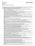
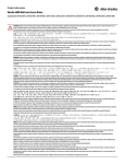
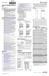
Product Information
PowerFlex 700 AC Drives, Frames 0...6
ATTENTION:
Read this document and the documents listed in the Additional Resources section about installation, configuration and operation of this equipment before you install, configure, operate or maintain this product. Users are required to
familiarize themselves with installation and wiring instructions in addition to requirements of all applicable codes, laws, and standards.
Activities including installation, adjustments, putting into service, use, assembly, disassembly, and maintenance are required to be carried out by suitably trained personnel in accordance with applicable code of practice.
If this equipment is used in a manner not specified by the manufacturer, the protection provided by the equipment may be impaired.
注意:
在安装、配置、操作和维护本产品前,请阅读本文档以及 “ 其他资源 ” 部分列出的有关设备安装、配置和操作的相应文档。除了所有适用规范、法律和标准的相关
要求之外,用户还必须熟悉安装和接线说明。
安装、调整、投运、使用、组装、拆卸和维护等各项操作必须由经过适当训练的专业人员按照适用的操作规范实施。
如果未按照制造商指定的方式使用该设备,则可能会损害设备提供的保护。
ATENCIÓN:
Antes de instalar, configurar, poner en funcionamiento o realizar el mantenimiento de este producto, lea este documento y los documentos listados en la sección Recursos adicionales acerca de la instalación, configuración y operación de este
equipo. Los usuarios deben familiarizarse con las instrucciones de instalación y cableado y con los requisitos de todos los códigos, leyes y estándares vigentes.
El personal debidamente capacitado debe realizar las actividades relacionadas a la instalación, ajustes, puesta en servicio, uso, ensamblaje, desensamblaje y mantenimiento de conformidad con el código de práctica aplicable.
Si este equipo se usa de una manera no especificada por el fabricante, la protección provista por el equipo puede resultar afectada.
ATENÇÃO:
Leia este e os demais documentos sobre instalação, configuração e operação do equipamento que estão na seção Recursos adicionais antes de instalar, configurar, operar ou manter este produto. Os usuários devem se familiarizar com as
instruções de instalação e fiação além das especificações para todos os códigos, leis e normas aplicáveis.
É necessário que as atividades, incluindo instalação, ajustes, colocação em serviço, utilização, montagem, desmontagem e manutenção sejam realizadas por pessoal qualificado e especializado, de acordo com o código de prática aplicável.
Caso este equipamento seja utilizado de maneira não estabelecida pelo fabricante, a proteção fornecida pelo equipamento pode ficar prejudicada.
ВНИМАНИЕ:
Перед тем как устанавливать, настраивать, эксплуатировать или обслуживать данное оборудование, прочитайте этот документ и документы, перечисленные в разделе «Дополнительные ресурсы». В этих документах
изложены сведения об установке, настройке и эксплуатации данного оборудования. Пользователи обязаны ознакомиться с инструкциями по установке и прокладке соединений, а также с требованиями всех применимых
норм, законов и стандартов.
Все действия, включая установку, наладку, ввод в эксплуатацию, использование, сборку, разборку и техническое обслуживание, должны выполняться обученным персоналом в соответствии с применимыми нормами и
правилами.
Если оборудование используется не предусмотренным производителем образом, защита оборудования может быть нарушена.
注意 :
本製品を設置、構成、稼動または保守する前に、本書および本機器の設置、設定、操作についての参考資料の該当箇所に記載されている文書に目を通してくださ
い。ユーザは、すべての該当する条例、法律、規格の要件に加えて、設置および配線の手順に習熟している必要があります。
設置調整、運転の開始、使用、組立て、解体、保守を含む諸作業は、該当する実施規則に従って訓練を受けた適切な作業員が実行する必要があります。
本機器が製造メーカにより指定されていない方法で使用されている場合、機器により提供されている保護が損なわれる恐れがあります。
ACHTUNG:
Lesen Sie dieses Dokument und die im Abschnitt „Literaturverweise“ genannten Dokumente zur Installation, Konfiguration und Bedienung dieser Ausrüstung sorgfältig durch, bevor Sie dieses Produkt installieren, konfigurieren, bedienen
oder instandsetzen. Benutzer müssen sich mit den Anweisungen zur Installation und Verdrahtung vertraut machen und müssen die Anforderungen aller geltenden Vorschriften, Gesetze und Normen kennen.
Aktivitäten wie Installation, Einstellung, Inbetriebnahme, Verwendung, Montage, Demontage und Instandsetzung müssen durch ausreichend geschultes Personal in Übereinstimmung mit den geltenden Durchführungsvorschriften
ausgeführt werden.
Wenn diese Ausrüstung in einer Weise verwendet wird, die nicht vom Hersteller angegeben wurde, kann der von der Ausrüstung bereitgestellte Schutz beeinträchtigt sein..
ATTENTION :
Lisez ce document et les documents listés dans la section Ressources complémentaires relatifs à l’installation, la configuration et le fonctionnement de cet équipement avant d’installer, configurer, utiliser ou entretenir ce produit. Les
utilisateurs doivent se familiariser avec les instructions d’installation et de câblage en plus des exigences relatives aux codes, lois et normes en vigueur.
Les activités relatives à l’installation, le réglage, la mise en service, l’utilisation, l’assemblage, le démontage et l’entretien doivent être réalisées par des personnes formées selon le code de pratique en vigueur.
Si cet équipement est utilisé d’une façon qui n’a pas été définie par le fabricant, la protection fournie par l’équipement peut être compromise.
주의 :
본 제품 설치, 설정, 작동 또는 유지 보수하기 전에 본 문서를 포함하여 설치, 설정 및 작동에 관한 참고 자료 섹션의 문서들을 반드시 읽고 숙지하십시오. 사용자는 모든
관련 규정 , 법규 및 표준에서 요구하는 사항에 대해 반드시 설치 및 배선 지침을 숙지해야 합니다 .
설치 , 조정 , 가동 , 사용 , 조립 , 분해 , 유지보수 등 모든 작업은 관련 규정에 따라 적절한 교육을 받은 사용자를 통해서만 수행해야 합니다 .
본 장비를 제조사가 명시하지 않은 방법으로 사용하면 장비의 보호 기능이 손상될 수 있습니다 .
ATTENZIONE
Prima di installare, configurare ed utilizzare il prodotto, o effettuare interventi di manutenzione su di esso, leggere il presente documento ed i documenti elencati nella sezione “Altre risorse”, riguardanti l’installazione, la configurazione ed il
funzionamento dell’apparecchiatura. Gli utenti devono leggere e comprendere le istruzioni di installazione e cablaggio, oltre ai requisiti previsti dalle leggi, codici e standard applicabili.
Le attività come installazione, regolazioni, utilizzo, assemblaggio, disassemblaggio e manutenzione devono essere svolte da personale adeguatamente addestrato, nel rispetto delle procedure previste.
Qualora l’apparecchio venga utilizzato con modalità diverse da quanto previsto dal produttore, la sua funzione di protezione potrebbe venire compromessa.
2 PowerFlex 700 AC Drives, Frames 0...6
DİKKAT:
Bu ürünün kurulumu, yapılandırılması, işletilmesi veya bakımı öncesinde bu dokümanı ve bu ekipmanın kurulumu, yapılandırılması ve işletimi ile ilgili İlave Kaynaklar bölümünde yer listelenmiş dokümanları okuyun. Kullanıcılar
yürürlükteki tüm yönetmelikler, yasalar ve standartların gereksinimlerine ek olarak kurulum ve kablolama talimatlarını da öğrenmek zorundadır.
Kurulum, ayarlama, hizmete alma, kullanma, parçaları birleştirme, parçaları sökme ve bakım gibi aktiviteler sadece uygun eğitimleri almış kişiler tarafından yürürlükteki uygulama yönetmeliklerine uygun şekilde yapılabilir.
Bu ekipman üretici tarafından belirlenmiş amacın dışında kullanılırsa, ekipman tarafından sağlanan koruma bozulabilir.
注意事項:
在安裝、設定、操作或維護本產品前,請先閱讀此文件以及列於 「其他資源」章節中有關安裝、設定與操作此設備的文件。使用者必須熟悉安裝和配線指示,
並符合所有法規、法律和標準要求。
包括安裝、調整、交付使用、使用、組裝、拆卸和維護等動作都必須交由已經過適當訓練的人員進行,以符合適用的實作法規。
如果將設備用於非製造商指定的用途時,可能會造成設備所提供的保護功能受損。
POZOR:
Než začnete instalovat, konfigurovat či provozovat tento výrobek nebo provádět jeho údržbu, přečtěte si tento dokument a dokumenty uvedené v části Dodatečné zdroje ohledně instalace, konfigurace a provozu tohoto zařízení.
Uživatelé se musejí vedle požadavků všech relevantních vyhlášek, zákonů a norem nutně seznámit také s pokyny pro instalaci a elektrické zapojení.
Činnosti zahrnující instalaci, nastavení, uvedení do provozu, užívání, montáž, demontáž a údržbu musí vykonávat vhodně proškolený personál v souladu s příslušnými prováděcími předpisy.
Pokud se toto zařízení používá způsobem neodpovídajícím specifikaci výrobce, může být narušena ochrana, kterou toto zařízení poskytuje.
UWAGA:
Przed instalacją, konfiguracją, użytkowaniem lub konserwacją tego produktu należy przeczytać niniejszy dokument oraz wszystkie dokumenty wymienione w sekcji Dodatkowe źródła omawiające instalację, konfigurację i
procedury użytkowania tego urządzenia. Użytkownicy mają obowiązek zapoznać się z instrukcjami dotyczącymi instalacji oraz oprzewodowania, jak również z obowiązującymi kodeksami, prawem i normami.
Działania obejmujące instalację, regulację, przekazanie do użytkowania, użytkowanie, montaż, demontaż oraz konserwację muszą być wykonywane przez odpowiednio przeszkolony personel zgodnie z obowiązującym kodeksem
postępowania.
Jeśli urządzenie jest użytkowane w sposób inny niż określony przez producenta, zabezpieczenie zapewniane przez urządzenie może zostać ograniczone.
OBS!
Läs detta dokument samt dokumentet, som står listat i avsnittet Övriga resurser, om installation, konfigurering och drift av denna utrustning innan du installerar, konfigurerar eller börjar använda eller utföra underhållsarbete på
produkten. Användare måste bekanta sig med instruktioner för installation och kabeldragning, förutom krav enligt gällande koder, lagar och standarder.
Åtgärder som installation, justering, service, användning, montering, demontering och underhållsarbete måste utföras av personal med lämplig utbildning enligt lämpligt bruk.
Om denna utrustning används på ett sätt som inte anges av tillverkaren kan det hända att utrustningens skyddsanordningar försätts ur funktion.
LET OP:
Lees dit document en de documenten die genoemd worden in de paragraaf Aanvullende informatie over de installatie, configuratie en bediening van deze apparatuur voordat u dit product installeert, configureert, bediend of
onderhoudt. Gebruikers moeten zich vertrouwd maken met de installatie en de bedradingsinstructies, naast de vereisten van alle toepasselijke regels, wetten en normen.
Activiteiten zoals het installeren, afstellen, in gebruik stellen, gebruiken, monteren, demonteren en het uitvoeren van onderhoud mogen uitsluitend worden uitgevoerd door hiervoor opgeleid personeel en in overeenstemming
met de geldende praktijkregels.
Indien de apparatuur wordt gebruikt op een wijze die niet is gespecificeerd door de fabrikant, dan bestaat het gevaar dat de beveiliging van de apparatuur niet goed werkt.
Additional Resources
These documents contain additional information concerning related products from Rockwell Automation.
Resource
Description
English
The installation instructions are available in multiple languages at
http://rockwellautomation.com/literature. Select publication language and type “20B-IN019” in the
search field.
Español
Puede encontrar las instrucciones de instalación en varios idiomas en
http://rockwellautomation.com/literature. Seleccione el idioma de publicación y escriba
“20B-IN019” en el campo de búsqueda.
Deutsch
Die Installationsanweisungen kann in mehreren Sprachen unter
http://rockwellautomation.com/literature gelesen werden.
Bitte Ihre Sprache anwählen und “20B-IN019” im Suchfeld eintippen.
Português
As instruções de instalação está disponível em várias línguas em
http://rockwellautomation.com/literature. Seleccione a língua de publicação e entre com
“20B-IN019” no espaço de busca.
Français
Les instructions d'installation sont disponibles dans différentes langues à l’adresse suivante:
http://rockwellautomation.com/literature. Sélectionner la langue puis taper << 20B-IN019 >> dans le
champ de recherche.
中文
( 简体 )
从以下网页可以获得安装说明多种语言的版本 :
http://rockwellautomation.com/literature。
请选择出版物的语言 , 并在搜索栏输入 “20B-IN019 印
Italiano
Le istruzioni per l'installazione disponibile in varie lingue sul sito
http://rockwellautomation.com/literature. Selezionare la lingua desiderata e digitare “20B-IN019” nel
campo di ricerca.
PowerFlex 700 Vector Control User Manual (v4.001 & up), publication 20B-UM002
Provides the basic information needed to install, start-up, and troubleshoot the PowerFlex 700 adjustable
frequency AC drive.
PowerFlex 700 Adjustable Frequency AC Drive Technical Data, publication 20B-TD001
Provides technical data regarding the PowerFlex 700 adjustable frequency AC drives for a variety of industrial
applications.
Wiring and Grounding Guidelines for Pulse Width Modulated (PWM) AC Drives, publication DRIVES-IN001
Provides basic information needed to properly wire and ground PWM AC drives.
Industry Installation Guidelines for Pulse Width Modulated (PWM) AC Drives Application Technique,
publication DRIVES-AT003
Provides basic information for different enclosure systems, and power and grounding considerations needed to
properly install a PWM AC drive.
Industrial Automation Wiring and Grounding Guidelines, publication 1770-4.1
Provides general guidelines for installing a Rockwell Automation industrial system.
Product Certifications website, http://www.rockwellautomation.com/products/certification
Provides declarations of conformity, certificates, and other certification details.
You can view or download publications at http://www.rockwellautomation.com/literature/. To order paper copies of technical documentation, contact your local Allen-Bradley distributor or Rockwell Automation sales representative.
Rockwell Automation Publication 20B-PC001C-EN-P - July 2013
PowerFlex 700 AC Drives, Frames 0...6 3
ATTENTION: Only qualified personnel familiar with adjustable frequency AC drives and associated machinery should plan or implement the installation, start-up and subsequent maintenance of the system. Failure to comply may
result in personal injury and/or equipment damage.
ATTENTION: An incorrectly applied or installed drive can result in component damage or a reduction in product life. Wiring or application errors such as under sizing the motor, incorrect or inadequate AC supply, or excessive
surrounding air temperatures may result in malfunction of the system.
ATTENTION: Drive must not be installed in an area where the ambient atmosphere contains volatile or corrosive gas, vapors or dust. If the drive is not going to be installed for a period of time, it must be stored in an area where it
will not be exposed to a corrosive atmosphere.
Operating Temperatures
PowerFlex 700 drives (frames 0...6) are designed to operate at 0…40 ° C (32…104 °F) ambient. To operate the drive in installations between 41…50 ° C (106…122 °F), see the information below and refer to pages 4 through 8 for exceptions.
Acceptable Surrounding Air Temperature & Required Actions
Enclosure Rating
IP20, NEMA/UL Type 1 (with Top Label)
(1)
Minimum Mounting Clearances
Temperature Range
Drive
0…40 ° C (32...104 °F)
Frames 0…4,
All Ratings
Frames 5…6,
Most Ratings (2)
0…50 ° C (32...122 °F)
0…50 ° C (32...122 °F)
IP20, NEMA/UL Type Open
(Top Label Removed) (1)
0…45 ° C (32...113 °F)
0…50 ° C (32...122 °F)
IP00, NEMA/UL Type Open
(Top Label & Vent Plate Removed)
Flange Mount
Front - IP00, NEMA/UL Type Open
Stand-alone/Wall Mount-IP54, NEMA/UL 12
(2)
(3)
101.6 mm
(4.0 in.)
20BC072 Only (3)
0…55 ° C (32...131 °F)
Front (Inside Encl.)
0…40 ° C (32...104 °F)
Back (External)
0…40 ° C (32...104 °F)
Back/Heat Sink-IP54, NEMA/UL Type 12
(1)
Most Ratings (2)
20BC072 Only
Specified vertical clearance requirements are intended to be from the drive to the closest object that can
restrict airflow through the drive heat sink and chassis. The drive must be mounted in a vertical orientation as
shown, and must make full contact with the mounting surface. Do not use standoffs or spacers. In addition,
inlet air temperature must not exceed the product specification.
Frames 5…6
101.6 mm
(4.0 in.)
101.6 mm
(4.0 in.)
PWR
PWR
STS
STS
PORT
PORT
MOD
MOD
NET A
NET A
NET B
NET B
No Adhesive Label
(see table, left)
PORT
MOD
NET A
NET B
With Adhesive Label
(see table, left)
101.6 mm
(4.0 in.)
PWR
PWR
STS
STS
50.8 mm
(2.0 in.)
PORT
MOD
NET A
NET B
Frames 5…6
Removing the adhesive top label from the drive changes the NEMA/UL enclosure rating from Type 1 to Open. Frames 5 and 6 do
not have a top label.
Refer to pages 4 through 8 for exceptions.
To remove vent plate (refer to User Manual for location), lift top edge of plate from the chassis. Rotate the plate out from the back
plate.
101.6 mm
(4.0 in.)
101.6 mm
(4.0 in.)
101.6 mm
(4.0 in.)
101.6 mm
(4.0 in.)
Drive Weights
Frame
Weight (1)
kg (lb)
Frame
Weight (1)
kg (lb)
NEMA/UL Type 12
(400…690V drives only)
Weight (1)
kg (lb)
0
1
2
3
5.22 (11.5)
7.03 (15.5)
12.52 (27.6)
18.55 (40.9)
4
5
6
24.49 (54.0)
37.19 (82.0)
71.44 (157.5)
Frame 5 NEMA/UL Type 12 Standalone
Frame 5 NEMA/UL Type 12 Flange Mount
Frame 6 NEMA/UL Type 12 Standalone
Frame 6 NEMA/UL Type 12 Flange Mount
102.51 (226.0)
61.69 (136.0)
176.90 (390)
99.79 (220.0)
(1)
Weights include HIM and Standard I/O.
Leakage Current
• PowerFlex 700 drives produce leakage current in the protective earthing conductor which exceeds 3.5 mA AC and/or 10 mA DC. The minimum size of the protective earthing (grounding) conductor used in the application must comply with
local safety regulations for high protective earthing conductor current equipment.
• PowerFlex 700 drives produce DC current in the protective earthing conductor and may reduce the ability of a residual current device (RCD) or residual current monitor (RCM) of type A or AC to provide protection for the drive and other
equipment in the installation.
Motor Overload Protection - PowerFlex 700 Drives with Standard Control
PowerFlex 700 drives with standard control, identified by an N, A, or B in position 15 of the catalog number, only provide Class 10 motor overload protection according to NEC article 430. They do not provide speed sensitive overload protection,
thermal memory retention and motor over-temperature sensing according to NEC article 430.126 (A) (2). If such protection is needed in the end-use product, it must be provided by additional means.
Motor Overload Protection - PowerFlex 700 Drives with Vector Control
PowerFlex 700 drives with vector control, identified by a C or D in position 15 of the catalog number, provide class 10 motor overload protection according to NEC article 430 and motor over-temperature protection according to NEC article 430.126
(A) (2). UL 508C File E59272.
Short Circuit Current Rating
Maximum Short Circuit Rating:
200,000 Amps symmetrical.
Branch Circuit Short Circuit Protection
Integral solid state short circuit protection does not provide branch circuit protection. Branch circuit protection must be provided in accordance with the National Electric Code (NEC) and any additional local codes, or the equivalent. The tables on
the following pages provide drive ratings (including continuous, 1 minute and 3 second) and recommended AC line input fuse and circuit breaker information. Both types of short circuit protection are acceptable for UL and IEC requirements. Sizes
listed are the recommended sizes based on 40 °C (104 °F) and the U.S. N.E.C. Other country, state or local codes can require different ratings.
Fuse and Circuit Breaker Ratings
The tables on the following pages provide recommended AC line input fuse and circuit breaker information. See Fusing and Circuit Breakers below for UL and IEC requirements. Sizes listed are the recommended sizes based on 40 °C (104 °F) and
the U.S. NEC. Other country, state, or local codes can require different ratings. Tables with DC link fuse recommendations for DC input drives are also provided.
Fusing
The recommended fuse types are listed below. If available current ratings do not match those listed in the tables provided, choose the next higher fuse rating.
• IEC – BS88 (British Standard) Parts 1 & 2, EN60269-1, Parts 1 & 21, type gG or equivalent should be used.
• UL - UL Class CC, T, RK1 or J should be used.
1
Typical designations include, but may not be limited to the following; Parts 1 & 2: AC, AD, BC, BD, CD, DD, ED, EFS, EF, FF, FG, GF, GG, GH.
Rockwell Automation Publication 20B-PC001C-EN-P - July 2013
4 PowerFlex 700 AC Drives, Frames 0...6
Circuit Breakers
600…690 Volt Single-Phase AC Input Rating (continued)
0
0
1
1
1
1
2
3
3
4
4
5
5
6
6
6
208V Single-Phase AC Input
Drive
Catalog
Number
20BB2P2
20BB4P2
20BB6P8
20BB9P6
20BB015
20BB022
20BB028
20BB042
20BB052
20BB070
20BB080
20BB104
20BB130
20BB154
20BB192
20BB260
0
0
1
1
1
1
2
3
3
4
4
5
5
6
6
6
Hp
Input Three-Phase
Rating Amps Output
V AC
Amps
0.25
1.7
0-200 1.3
0.5
3.2
0-200 2.4
1
5.9
0-200 3.9
1.5
8.3
0-200 5.5
2.5
13.6 0-200 8.8
3.75
19.9 0-200 12.7
5
25.7 0-200 16.1
7.5
38.5 0-200 24.2
10
44.6 0-200 28
12.5
62.3 0-200 39.1
15
73.3 0-200 46
20
97.9 0-200 60
25
106.1 0-200 65
30
144.4 0-200 88.5
37.5
180.3 0-200 110.5
50
212.1 0-200 130
Temp.
°C
25
25
25
25
25
25
25
25
25
25
25
25
25
25
25
25
380…480 Volt Single-Phase AC Input Ratings
20BD1P1
20BD2P1
20BD3P4
20BD5P0
20BD8P0
20BD011
20BD014
20BD022
20BD027
20BD034
20BD040
20BD052
20BD065
20BD077
20BD096
20BD125
–
20BD156
20BD180
20BD248
0
0
0
0
0
0
1
1
2
2
3
3
3
4
5
5
–
6
6
6
Hp
Input Three-Phase
Rating Amps Output
V AC Amps
0.25
0.7
0-460 0.6
0.5
1.4
0-460 1.1
1
2.3
0-460 1.7
1.5
3.4
0-460 2.5
2.5
6
0-460 4
3.75
8.2
0-460 5.5
5
10.9 0-460 7
7.5
17.3 0-460 11
10
21.4 0-460 13.5
12.5
27
0-460 17
15
31.8 0-460 20
20
41.3 0-460 26
25
51.6 0-460 32.5
30
62.6 0-460 38.5
37.5
78.1 0-460 48
50
101.6 0-460 62.5
–
–
–
–
62.5
126.8 0-460 78
75
146.4 0-460 90
100
201.6 0-460 124
380…400V Single-Phase AC Input
Drive
Catalog
Number
Frame
Drive
Catalog
Number
Frame
480V Single-Phase AC Input
20BC1P3
20BC2P1
20BC3P5
20BC5P0
20BC8P7
20BC011
20BC015
20BC022
20BC030
20BC037
20BC043
20BC056
20BC072
20BC085
20BC105
20BC125
20BC140
20BC170
20BC205
20BC260
0
0
0
0
0
0
1
1
2
2
3
3
3
4
5
5
5
6
6
6
kW
Input Three-Phase
Rating Amps Output
V AC
Amps
0.2
1
0-400 0.7
0.4
1.6
0-400 1.1
0.75
2.7
0-400 1.8
1.1
3.9
0-400 2.5
2
6.9
0-400 4.4
2.75
9.3
0-400 5.8
3.75
12.5 0-400 7.7
5.5
17.8 0-400 11
7.5
24.6 0-400 15
9.25
30.3 0-400 18.5
11
35.2 0-400 21.5
15
45.9 0-400 28
18.5
59.7 0-400 36
22.5
70.5 0-400 42.5
27.5
87
0-400 52.5
27.5
103.6 0-400 62.5
37.5
117.4 0-400 70
45
142.6 0-400 85
55
171.9 0-400 102.5
66
220.6 0-400 130
Temp.
°C
25
25
25
25
25
25
25
25
25
25
25
25
25
25
25
25
25
25
25
25
600…690 Volt Single-Phase AC Input Rating
20BE1P7
20BE2P7
20BE3P9
20BE6P1
20BE9P0
20BE011
0
0
0
0
0
1
Hp
Input Three-Phase
Rating Amps Output
V AC
Amps
0.5
1.1
0-575 0.9
1
1.8
0-575 1.4
1.5
2.6
0-575 2
2.5
4.6
0-575 3.1
3.75
6.7
0-575 4.5
5
8.5
0-575 5.5
690V Single-Phase AC Input
Drive
Catalog
Number
Frame
Drive
Catalog
Number
Frame
600V Single-Phase AC Input
–
–
–
–
–
–
–
–
–
–
–
–
kW
Input Three-Phase
Rating Amps Output
V AC Amps
–
–
–
–
–
–
–
–
–
–
–
–
–
–
–
–
–
–
–
–
–
–
–
–
Temp.
°C
25
25
25
25
25
25
1
2
2
3
3
3
4
5
5
6
6
Drive
Catalog
Number
Frame
20BB2P2
20BB4P2
20BB6P8
20BB9P6
20BB015
20BB022
20BB028
20BB042
20BB052
20BB070
20BB080
20BB104
20BB130
20BB154
20BB192
20BB260
Hp
Input Three-Phase
Rating Amps Output
V AC Amps
0.25
1.5
0-230 1.1
0.5
2.8
0-230 2.1
1
5.1
0-230 3.4
1.5
7.2
0-230 4.8
2.5
11.9 0-230 7.7
3.75
17.3 0-230 11
5
22.2 0-230 14
7.5
33.4 0-230 21
10
41.3 0-230 26
12.5
55.6 0-230 35
15
63.6 0-230 40
20
84.6 0-230 52
25
105.7 0-230 65
30
125.2 0-230 77
37.5
156.1 0-230 96
50
211.4 0-230 130
Frame
Drive
Catalog
Number
Frame
240V Single-Phase AC Input
Frame
208/240 Volt Single-Phase AC Input Ratings
20BE017
20BE022
20BE027
20BE032
20BE041
20BE052
20BE062
20BE077
20BE099
20BE125
20BE144
690V Single-Phase AC Input
Hp
Input Three-Phase
Rating Amps Output
V AC
Amps
7.5
13.3 0-575 8.5
10
17.5 0-575 11
12.5
21.4 0-575 13.5
15
25.4 0-575 16
20
32.6 0-575 20.5
25
41.3 0-575 26
30
50.4 0-575 31
37.5
62.6 0-575 38.5
50
80.5 0-575 49.5
62.5
101.6 0-575 62.5
75
117.1 0-575 72
–
–
–
–
–
20BF052
20BF060
20BF082
20BF098
20BF119
20BF142
–
–
–
–
–
5
5
5
5
6
6
Temp.
kW
Input Three-Phase
Rating Amps Output
V AC Amps
–
–
–
–
–
–
–
–
–
–
–
–
–
–
–
–
–
–
–
–
22.5
43.1 0-690 26
27.5
49.9 0-690 30
37.5
68.4 0-690 41
45
82
0-690 49
55
100
0-690 59.5
66
120.2 0-690 71
°C
25
25
25
25
25
25
25
25
25
25
25
DC Input Protection Devices
325 Volt DC Input Protection Devices (See page 5 for Notes)
Drive
Catalog
Number
Frame
Single-phase AC Input Ratings
600V Single-Phase AC Input
Drive
Catalog
Number
20BB2P2
20BB4P2
20BB6P8
20BB9P6
20BB015
20BB022
20BB028
20BB042
20BB052
20BB070
20BB080
0
0
1
1
1
1
2
3
3
4
4
20BN104 (3) 5
20BN130 (3) 5
20BN154 (3) 6
20BN192 (3) 6
20BN260 (3) 6
Hp Rating PWM Temp. DC Input Output Amps
Freq. (1)
Ratings
ND
0.5
1
2
3
5
7.5
10
15
20
25
30
40
–
50
–
60
–
75
–
100
–
HD
0.33
0.75
1.5
2
3
5
7.5
10
15
20
25
–
30
–
40
–
50
–
60
–
75
kHz
4
4
4
4
4
4
4
4
4
4
4
4
4
4
4
4
4
4
4
2
2
°C
50
50
50
50
50
50
50
50
50
50
50
50
50
50
50
50
50
50
50
45
50
Amps
2
3.8
6.9
9.7
16
23.3
30
45
55
75.3
86.8
114.1
85.8
142.6
114.1
169
142.6
210.6
169
285.3
210.6
Cont.
2.2
4.2
6.8
9.6
15.3
22
28
42
52
70
80
104
80
130
104
154
130
192
154
260
205
1 Min.
2.4
4.8
9
10.6
16.8
24.2
33
46.2
63
78
105
115
120
143
156
169
195
211
231
286
305
Fuse Non-Time
Delay Fuse
3 Sec.
3.3
6.4
12
14.4
23
33
44
63
80
105
140
175
160
175
175
231
260
288
308
390
410
(2) (11)
5
10
15
20
30
45
60
90
100
150
175
200
200
200
200
300
300
350
350
400
400
JKS-5
JKS-10
HSJ15
HSJ20
HSJ30
HSJ45
HSJ60
HSJ90
HSJ100
HSJ150
HSJ175
HSJ200
HSJ200
HSJ200
HSJ200
HSJ300
HSJ300
HSJ350
HSJ350
HSJ400
HSJ400
540 Volt DC Input Protection Devices (See page 5 for Notes)
Drive
Catalog
Number
Frame
The “non-fuse” listings in the following tables include inverse time circuit breakers, instantaneous trip circuit breakers
(motor circuit protectors) and 140M self-protected combination motor controllers. If one of these is chosen as the
desired protection method, the following requirements apply:
• IEC – Both types of circuit breakers and 140M self-protected combination motor controllers are acceptable for
IEC installations.
• UL - Only inverse time circuit breakers and the specified 140M self-protected combination motor controllers are
acceptable for UL installations.
20BC1P3
20BC2P1
20BC3P5
20BC5P0
20BC8P7
20BC011
20BC015
20BC022
20BC030
20BC037
20BC043
20BC056
20BC072
0
0
0
0
0
0
1
1
2
2
3
3
3
20BC085 (3)(5) 4
20BH105 (3)(5) 5
kW
Rating
ND HD
0.37 0.25
0.75 0.55
1.5 0.75
2.2 1.5
4
3
5.5 4
7.5 5.5
11 7.5
15 11
18.5 15
22 18.5
30 22
37 30
PWM
Freq.
kHz
4
4
4
4
4
4
4
4
4
4
4
4
4
Temp. DC Input
(1)
Ratings
°C
Amps kW
50
1.3
–
50
2.1
–
50
3.7
–
50
5.3
–
50
9.3
–
50
12.6 –
50
16.8 –
50
24
–
50
33.2 –
50
40.9 –
50
47.5 –
50
61.9 –
50 (7) 80.5 –
45
–
55
–
37
–
4
4
4
45
45
–
45
4
Rockwell Automation Publication 20B-PC001C-EN-P - July 2013
Output Amps
Fuse
Non-Time
Delay Fuse
(2) (11)
Cont.
1.3
2.1
3.5
5
8.7
11.5
15.4
22
30
37
43
56
72
1 Min.
1.4
2.4
4.5
5.5
9.9
13
17.2
24.2
33
45
56
64
84
3 Sec.
1.9
3.2
6
7.5
13.2
17.4
23.1
33
45
60
74
86
112
3
6
8
10
15
20
25
40
50
70
90
100
125
JKS-3
JKS-6
JKS-8
JKS-10
HSJ15
HSJ20
HSJ25
HSJ40
HSJ50
HSJ70
HSJ90
HSJ100
HSJ125
50 (4)
95.1 –
80.5 –
120.2 –
85
72
105
94
108
116
128
144
158
150
175
175
HSJ150
HSJ175
HSJ175
50 (4)
95.1
85
128
170
200
HSJ200
–
PowerFlex 700 AC Drives, Frames 0...6 5
20BH170 (3)(5) 6
20BH205 (3)(5)
6
20BH260 (3)(5) 6
Temp. DC Input
(1)
Ratings
°C
Amps kW
40 (4) 159 –
Output Amps
650 Volt DC Input Protection Devices (See page 5 for Notes) (continued)
Fuse
Cont. 1 Min. 3 Sec.
140 154
190 225
(2) (11)
Drive
Catalog
Number
Frame
5
PWM
Freq.
kHz
4
Non-Time
Delay Fuse
HSJ225
20BR248 (3)(6)
6
–
55
4
40 (4)
120.2 –
105
158
190
225
HSJ225
90
–
4
50 (4)
192.3 –
170
187
255
300
HSJ300
–
75
4
50 (4)
159
–
140
210
280
300
HSJ300
110 –
4
40 (4)
226
–
205
220
289
350
HSJ350
–
90
4
40 (4)
192.3 –
170
255
313
350
HSJ350
132 –
2
45 (4)
298
–
260
286
390
500
HSJ500
110 2
50 (4)
226
–
205
305
410
500
HSJ500
–
650 Volt DC Input Protection Devices (See page 5 for Notes)
20BR096 (3)(6) 5
Hp Rating PWM
Freq.
ND HD kHz
0.5 0.33 4
1
0.75 4
2
1.5 4
3
2
4
5
3
4
7.5 5
4
10 7.5 4
15 10 4
20 15 4
25 20 4
30 25 4
40 30 4
50 40 4
60 –
4
–
50 4
75 –
4
60
4
50 (4)
84.5
77
116
154
175
HSJ175
20BR125 (3)(6) 5
100 –
4
50 (4)
137.1 –
125
138
163
200
HSJ200
–
75
4
50 (4)
105.3 –
96
144
168
200
HSJ200
125 –
4
50 (4)
171.2 –
156
172
234
300
HSJ300
100 4
50 (4)
137.1 –
125
188
250
300
HSJ300
4
50 (4)
204
–
180
198
270
400
HSJ400
125 4
(4)
171.2 –
156
234
312
400
HSJ400
20BD1P1
20BD2P1
20BD3P4
20BD5P0
20BD8P0
20BD011
20BD014
20BD022
20BD027
20BD034
20BD040
20BD052
20BD065
20BD077 (3)
Frame
Drive
Catalog
Number
0
0
0
0
0
0
1
1
2
2
3
3
3
4
–
20BR156 (3)(6) 6
–
20BR180 (3)(6) 6
150 –
–
Temp. DC Input
Ratings
°C
Amps kW
50
1.0
–
50
1.9
–
50
3.0
–
50
4.5
–
50
8.1
–
50
11.1 –
50
14.7 –
50
23.3 –
50
28.9 –
50
36.4 –
50
42.9 –
50
55.7 –
50
69.7 –
50
84.5 –
50
69.7 –
50 (4) 105.3 –
Output Amps
Fuse Non-Time
Delay Fuse
(1)
50
–
(2) (11)
Cont.
1.1
2.1
3.4
5.0
8.0
11
14
22
27
34
40
52
65
77
65
96
1 Min.
1.2
2.4
4.5
5.5
8.8
12.1
16.5
24.2
33
40.5
51
60
78
85
98
106
3 Sec.
1.6
3.2
6.0
7.5
12
16.5
22
33
44
54
68
80
104
116
130
144
3
6
6
10
15
20
30
40
50
60
80
90
100
150
150
175
JKS-3
JKS-6
JKS-6
JKS-10
HSJ15
HSJ20
HSJ30
HSJ40
HSJ50
HSJ60
HSJ80
HSJ90
HSJ100
HSJ150
HSJ150
HSJ175
Hp Rating PWM
Freq.
ND HD kHz
200 –
2
Temp. DC Input
Ratings
°C
Amps kW
–
45 (4) 272
–
50 (4)
150 2
Output Amps
Fuse Non-Time
Delay Fuse
(1)
204
–
(2) (11)
Cont. 1 Min. 3 Sec.
248 273
372
400
HSJ400
180
HSJ400
270
360
400
Notes:
810 Volt DC Input Protection Devices (See page 5 for Notes)
Drive Catalog
Number
20BE1P7
20BE2P7
20BE3P9
20BE6P1
20BE9P0
20BE011
20BE017
20BE022
20BE027
20BE032
20BE041
20BE052
20BE062
Frame
20BH140 (3)(5)
kW
Rating
ND HD
75 –
20BT099 (3)
0
0
0
0
0
0
1
2
2
3
3
3
4
5
20BT144 (3)
6
Hp Rating
PWM Temp. DC Input Output Amps
Freq. (1)
Ratings
ND
1
2
3
5
7.5
10
15
20
25
30
40
50
60
100
–
150
–
kHz
4
4
4
4
4
4
4
4
4
4
4
4
2
2
2
2
2
HD
0.75
1.5
2
3
5
7.5
10
15
20
25
30
40
50
–
75
–
125
°C
50
50
50
50
50
50
50
50
50
50
50
50
50
40
40
50
50
Amps
1.5
2.4
3.5
6.2
9.1
11.5
18
23.6
29
34.3
43.9
55.7
68
108.6
84.5
158
137.1
Cont.
1.7
2.7
3.9
6.1
9
11
17
22
27
32
41
52
62
99
77
144
125
1 Min.
2
3.6
4.3
6.7
9.9
13.5
18.7
25.5
33
40.5
48
61.5
78
109
116
158
188
Fuse Non-Time
Delay Fuse
3 Sec.
2.6
4.8
5.9
9.2
13.5
18
25.5
34
44
54
64
82
104
126
138
216
250
(2) (11)
3
6
6
10
15
20
30
40
50
60
70
90
125
150
150
250
250
JKS-3
JKS-6
JKS-6
JKS-10
HSJ15
HSJ20
HSJ30
HSJ40
HSJ50
HSJ60
HSJ70
HSJ90
HSJ125
HSJ150
HSJ150
HSJ250
HSJ250
932 Volt DC Input Protection Devices (See page 5 for Notes)
Drive Catalog
Number
20BW052 (3)
20BW098 (3)
20BW142 (3)
Frame
Drive
Catalog
Number
Frame
540 Volt DC Input Protection Devices (See page 5 for Notes) (continued)
5
5
6
kW Rating PWM Temp. DC Input Output Amps
Freq. (1)
Ratings
ND
45
HD
–
–
Amps
58.2
Cont.
52
1 Min.
57
3 Sec.
78
100
170M3691
37.5 2
50 (4)
46.9
46
69
92
100
170M3691
90
–
2
50 (4)
110.7
98
108
127
160
170M3693
–
75
2
50 (4)
92.3
82
123
140
160
170M3693
132 –
2
50 (4)
162.2
142
156
213
250
170M3695
110 2
40 (4)
134.9
119
179
238
315
170M3696
(1)
°C
(2) (11)
50 (4)
–
kHz
2
Fuse Non-Time
Delay Fuse
Drive frames 0…4 temperature rating is for NEMA/UL Type Open. The adhesive top label must be removed to operate drive at this temperature. Frames 5 & 6 do not have a top label.
The power source to common bus inverters must be derived from AC voltages 600V or less, as defined in NFPA70; Art 430-18 (NEC). Battery supplies or MG sets are not included. The following devices were validated to break current of the
derived power DC Bus.
Disconnects: Allen-Bradley Bulletin 1494, 30-400A; 194, 30-400A; or ABB OESA, 600 & 800A; OESL, all sizes.
Fuses: Bussmann Type JKS, all sizes; Type 170M, Case Sizes 1, 2 and 3, or Ferraz Shawmut Type HSJ, all sizes. For any other devices, please contact the factory.
(3)
Drives have dual current ratings; one for normal duty applications, and one for heavy duty applications. The drive may be operated at either rating.
(4)
UL Type 12/IP54 (flange mount) heatsink ambient temperature rating is 40 °C/ambient of unprotected drive portion (inside enclosure) is 55 °C. The ambient temperature for the UL Type 12/IP54 stand-alone drives is 40 °C.
(5)
Also applies to “P” voltage class.
(6)
Also applies to “J” voltage class.
(7)
Must remove top label and vent plate, drive enclosure rating will be IP00, NEMA/UL Type Open.
(8)
Two 630A Bussmann 170M6608 can also be used.
(9)
Two 700A Bussmann 170M6611 can also be used.
(10)
Bussmann or equivalent.
(11)
See Fuse Certification and Test Data in PowerFlex AC Drives in Common Bus Configurations Application Guidelines, publication DRIVES-AT002, for fuse self-certification and test data for Bussmann 170M and JKS fuses recommended for the DC
bus fusing.
(2)
Rockwell Automation Publication 20B-PC001C-EN-P - July 2013
6 PowerFlex 700 AC Drives, Frames 0...6
AC Input Protection Devices
208 Volt AC Input Protection Devices (See page 8 for Notes)
Hp Rating PWM Temp.(11) Input Ratings Output Amps
Freq.
Frame
Drive
Catalog
Number
20BB2P2
20BB4P2
20BB6P8
20BB9P6
20BB015
20BB022
20BB028
20BB042
20BB052
20BB070
20BB080
0
0
1
1
1
1
2
3
3
4
4
20BB104(12) 5
20BB130(12) 5
20BB154(12) 6
20BB192(12) 6
20BB260(12) 6
Dual Element
Non-Time Delay
Time Delay Fuse Fuse
ND
HD
kHz
°C
Amps
kVA
Cont. 1 Min. 3 Sec. Min. (1)
Max. (2) Min. (1)
Max. (2)
0.5
1
2
3
5
7.5
10
15
20
25
30
40
–
50
–
60
–
75
–
100
–
0.33
0.75
1.5
2
3
5
7.5
10
15
20
25
–
30
–
40
–
50
–
60
–
75
4
4
4
4
4
4
4
4
4
4
4
4
4
4
4
4
4
4
4
2
2
50
50
50
50
50
50
50
50
50
50
50
50
50
50
50
50
50
50
50
45
50
1.9
3.7
6.8
9.5
15.7
23
29.6
44.5
51.5
72
84.7
113
84.7
141
113
167
141
208
167
255
199
0.7
1.3
2.4
3.4
5.7
8.3
10.7
16
17.1
25.9
30.5
40.7
30.5
44.1
35.3
60.1
50.9
75
60.1
91.9
71.7
2.5
4.8
7.8
11
17.5
25.3
32.2
48.3
56
78.2
92
120
92
130
104
177
150
221
177
260
205
6
10
15
20
35
50
70
100
125
175
200
250
200
275
225
350
300
450
350
575
450
10
17.5
30
40
70
100
125
175
200
300
350
475
350
500
400
500
500
600
500
750
600
2.8
5.6
10.4
12.1
19.3
27.8
38
53.1
64
93
117
132
138
143
156
195
225
243
266
286
305
3.8
7
13.8
17
26.3
38
50.6
72.5
86
124
156
175
175
175
175
266
300
308
308
390
410
3
6
10
12
20
30
40
60
80
90
110
150
125
175
125
225
200
300
225
300
225
3
6
10
12
20
30
40
60
80
90
110
150
125
175
125
225
200
300
225
300
225
Circuit
Motor Circuit 140M Motor Protector with Adjustable Current Range (5)(6)
Breaker (3) Protector (4)
Minimum Enclosure
Max. (8)
Max. (8)
Available Catalog Numbers - 140… (7)
Volume (in.3)(14)
15
3
M-C2E-B25 M-D8E-B25 –
7269
15
7
M-C2E-B63 M-D8E-B63 –
7269
30
15
M-C2E-C10 M-D8E-C10 M-F8E-C10 7269
40
15
M-C2E-C16 M-D8E-C16 M-F8E-C16 7269
70
30
M-C2E-C20 M-D8E-C20 M-F8E-C20 7269
100
30
–
M-D8E-C25 M-F8E-C25 7269
125
50
–
–
M-F8E-C32 7269
175
70
–
–
M-F8E-C45 13630
200
100
–
–
–
–
300
100
–
–
–
–
350
150
–
–
–
–
350
150
–
–
–
–
300
150
–
–
–
–
375
250
–
–
–
–
300
150
–
–
–
–
500
250
–
–
–
–
450
250
–
–
–
–
600
400
–
–
–
–
500
250
–
–
–
–
750
400
–
–
–
–
600
400
–
–
–
–
240 Volt AC Input Protection Devices (See page 8 for Notes)
Hp Rating PWM Temp.(11) Input Ratings Output Amps
Freq.
Frame
Drive
Catalog
Number
20BB2P2
20BB4P2
20BB6P8
20BB9P6
20BB015
20BB022
20BB028
20BB042
20BB052
20BB070
20BB080
0
0
1
1
1
1
2
3
3
4
4
20BB104(12) 5
20BB130(12) 5
20BB154(12) 6
20BB192(12) 6
20BB260(12) 6
Dual Element
Time Delay Fuse
Non-Time Delay
Fuse
ND
HD
kHz
°C
Amps
kVA
Cont.
1 Min. 3 Sec.
Min. (1)
Max. (2)
Min. (1)
0.5
1
2
3
5
7.5
10
15
20
25
30
40
–
50
–
60
–
75
–
100
–
0.33
0.75
1.5
2
3
5
7.5
10
15
20
25
–
30
–
40
–
50
–
60
–
75
4
4
4
4
4
4
4
4
4
4
4
4
4
4
4
4
4
4
4
2
2
50
50
50
50
50
50
50
50
50
50
50
50
50
50
50
50
50
50
50
45
50
1.7
3.3
5.9
8.3
13.7
19.9
25.7
38.5
47.7
64.2
73.2
98
73
122
98
145
122
180
145
233
169
0.7
1.4
2.4
3.4
5.7
8.3
10.7
16
19.8
26.7
30.5
40.6
30.5
50.7
40.6
60.1
50.7
74.9
60.1
96.7
70.1
2.2
4.2
6.8
9.6
15.3
22
28
42
52
70
80
104
80
130
104
154
130
192
154
260
205
2.4
4.8
9
10.6
16.8
24.2
33
46.2
63
78
105
115
120
143
156
169
195
211
231
286
305
3
5
10
12
20
25
35
50
60
90
100
125
100
175
125
200
175
225
200
300
225
6
8
15
20
30
50
60
90
100
150
180
225
175
275
225
300
275
400
300
575
450
3
5
10
12
20
25
35
50
60
90
100
125
100
175
125
200
175
225
200
300
225
3.3
6.4
12
14.4
23
33
44
63
80
105
140
175
160
175
175
231
260
288
308
390
410
Circuit
Motor Circuit 140M Motor Protector with Adjustable Current Range (5)(6)
Breaker (3) Protector (4)
Minimum Enclosure
Max. (2) Max. (8)
Max. (8)
Available Catalog Numbers - 140… (7)
Volume (in.3)(14)
10
15
3
M-C2E-B25 M-D8E-B25 –
7269
15
15
7
M-C2E-B63 M-D8E-B63 –
7269
25
25
15
M-C2E-C10 M-D8E-C10 M-F8E-C10 7269
35
35
15
M-C2E-C10 M-D8E-C10 M-F8E-C10 7269
60
60
30
M-C2E-C16 M-D8E-C16 M-F8E-C16 7269
80
80
30
–
M-D8E-C25 M-F8E-C25 7269
100
100
50
–
–
M-F8E-C32 7269
150
150
50
–
–
M-F8E-C45 13630
200
200
100
–
–
–
–
275
275
100
–
–
–
–
300
300
100
–
–
–
–
400
300
150
–
–
–
–
300
300
100
–
–
–
–
500
375
250
–
–
–
–
400
300
150
–
–
–
–
600
450
250
–
–
–
–
500
375
250
–
–
–
–
600
575
250
–
–
–
–
600
450
250
–
–
–
–
750
750
300
–
–
–
–
600
600
250
–
–
–
–
Rockwell Automation Publication 20B-PC001C-EN-P - July 2013
PowerFlex 700 AC Drives, Frames 0...6 7
400 Volt AC Input Protection Devices (See page 8 for Notes)
kW Rating PWM Temp.
Freq.
Frame
Drive
Catalog
Number
ND
HD
Input Ratings Output Amps
Dual Element
Time Delay Fuse
Non-Time Delay
Fuse
Min. (1)
Min. (1)
kHz
°C
Amps
kVA
Cont.
1 Min. 3 Sec.
Max. (2)
20BC1P3
0
0.37
0.25
4
50 (11)
1.1
0.77
1.3
1.4
1.9
3
3
3
20BC2P1
0
0.75
0.55
4
50 (11)
1.8
1.3
2.1
2.4
3.2
3
6
3
20BC3P5
0
1.5
0.75
4
50 (11)
3.2
2.2
3.5
4.5
6
6
7
6
20BC5P0
0
2.2
1.5
4
50 (11)
4.6
3.2
5
5.5
7.5
6
10
6
20BC8P7
0
4
2.2
4
50 (11)
7.9
5.5
8.7
9.9
13.2
15
17.5
15
20BC011
0
5.5
4
4
50 (11)
10.8
7.5
11.5
13
17.4
15
25
15
20BC015
1
7.5
5.5
4
50 (11)
14.4
10
15.4
17.2
23.1
20
30
20
20BC022
1
11
7.5
4
50 (11)
20.6
14.3
22
24.2
33
30
45
30
20BC030
2
15
11
4
50 (11)
28.4
19.7
30
33
45
35
60
35
20BC037
2
18.5
15
4
50 (11)
35
24.3
37
45
60
45
80
45
Circuit
Motor Circuit 140M Motor Protector with Adjustable Current Range (5)(6)
Breaker (3) Protector (4)
Minimum Enclosure
Max. (2) Max. (8)
Max. (8)
Available Catalog Numbers - 140… (7)
Volume (in.3)(14)
6
15
3
M-C2E-B16
–
–
7269
8
15
3
M-C2E-B25
M-D8E-B25
–
7269
12
15
7
M-C2E-B40
M-D8E-B40
–
7269
20
20
7
M-C2E-B63
M-D8E-B63
–
7269
30
30
15
M-C2E-C10
M-D8E-C10
M-F8E-C10
7269
45
45
15
M-C2E-C16
M-D8E-C16
M-F8E-C16
7269
60
60
20
M-C2E-C20
M-D8E-C20
M-F8E-C20
7269
80
80
30
M-D8E-C25
M-F8E-C25
–
7269
120
120
50
–
–
M-F8E-C32
7269
125
125
50
–
–
M-F8E-C45
7269
20BC043
3
22
18.5
4
50 (11)
40.7
28.2
43
56
74
60
90
60
150
150
60
–
–
–
–
20BC056
3
30
22
4
50 (11)
53
36.7
56
64
86
70
125
70
200
200
100
–
–
–
–
20BC072
3
37
30
4
50 (10)(11)
68.9
47.8
72
84
112
90
150
90
250
250
100
–
–
–
–
20BC085 (12)
4
45
–
4
45 (11)
81.4
56.4
85
94
128
110
200
110
300
300
150
–
–
–
–
–
37
4
45 (11)
68.9
47.8
72
108
144
90
175
90
275
300
100
–
–
–
–
20BC105 (12)
5
55
–
4
50 (9)
100.5
69.6
105
116
158
125
225
125
400
300
150
–
–
–
–
–
45
4
50 (9)
81.4
56.4
85
128
170
110
175
110
300
300
150
–
–
–
–
20BC125 (12)
5
55
–
4
50 (9)
121.1
83.9
125
138
163
150
275
150
500
375
250
–
–
–
–
–
45
4
50 (9)
91.9
63.7
96
144
168
125
200
125
375
375
150
–
–
–
–
20BC140 (12)
5
75
–
4
40 (9)
136
93.9
140
154
190
200
300
200
400
400
250
–
–
–
–
–
55
4
40 (9)
101
69.6
105
157
190
150
225
150
300
300
150
–
–
–
–
20BC170 (12)
6
90
–
4
50 (9)
164
126
170
187
255
250
375
250
600
500
250
–
–
–
–
–
75
4
50 (9)
136
103
140
210
280
200
300
200
550
400
250
–
–
–
–
110
–
4
40 (9)
199
148
205
220
289
250
450
250
600
600
400
–
–
–
–
–
90
4
40 (9)
164
126
170
255
313
250
375
250
600
500
250
–
–
–
–
132
–
2
45 (9)
255
177
260
286
390
350
550
350
750
750
400
–
–
–
–
–
110
2
50 (9)
199
138
205
308
410
250
450
250
600
600
400
–
–
–
–
20BC205 (12)
6
20BC260 (12)
6
Drive
Catalog
Number
Frame
480 Volt AC Input Protection Devices (See page 8 for Notes)
Hp Rating PWM
Freq.
Temp.
Input Ratings Output Amps
ND
°C
Amps
kVA
Cont. 1 Min. 3 Sec. Min. (1)
Max. (2)
Min. (1)
Max. (2)
6
HD
kHz
Dual Element
Time Delay Fuse
Non-Time Delay
Fuse
20BD1P1
0
0.5
0.33 4
50 (11)
0.9
0.7
1.1
1.2
1.6
3
3
3
20BD2P1
0
1
0.75 4
50 (11)
1.6
1.4
2.1
2.4
3.2
3
6
3
8
20BD3P4
0
2
1.5
4
50 (11)
2.6
2.2
3.4
4.5
6
4
8
4
12
Circuit
Motor Circuit 140M Motor Protector with Adjustable Current Range (5)(6)
Breaker (3) Protector (4)
Minimum Enclosure
Max. (8)
Max. (8)
Available Catalog Numbers - 140… (7)
Volume (in.3)(14)
15
3
M-C2E-B16
–
–
7269
15
3
M-C2E-B25
–
–
7269
15
7
M-C2E-B40
M-D8E-B40
–
7269
20
7
M-C2E-B63
M-D8E-B63
–
7269
30
15
M-C2E-C10
M-D8E-C10
M-F8E-C10
7269
40
15
M-C2E-C16
M-D8E-C16
M-F8E-C16
7269
50
20
M-C2E-C16
M-D8E-C16
M-F8E-C16
7269
80
30
M-D8E-C25
M-F8E-C25
–
7269
100
50
–
–
M-F8E-C32
7269
125
50
–
–
M-F8E-C45
7269
150
50
–
–
M-F8E-C45
13630
20BD5P0
0
3
2
4
50 (11)
3.9
3.2
5
5.5
7.5
6
10
6
20
20BD8P0
0
5
3
4
50 (11)
6.9
5.7
8
8.8
12
10
15
10
30
20BD011
0
7.5
5
4
50 (11)
9.5
7.9
11
12.1
16.5
15
20
15
40
20BD014
1
10
7.5
4
50 (11)
12.5
10.4
14
16.5
22
17.5
30
17.5
50
20BD022
1
15
10
4
50 (11)
19.9
16.6
22
24.2
33
25
50
25
80
20BD027
2
20
15
4
50 (11)
24.8
20.6
27
33
44
35
60
35
100
20BD034
2
25
20
4
50 (11)
31.2
25.9
34
40.5
54
40
70
40
125
20BD040
3
30
25
4
50 (11)
36.7
30.5
40
51
68
50
90
50
150
20BD052
3
40
30
4
50 (11)
47.7
39.7
52
60
80
60
110
60
200
200
70
–
–
–
–
20BD065
3
50
40
4
50 (11)
59.6
49.6
65
78
104
80
125
80
250
250
100
–
–
–
–
20BD077 (12)
4
60
–
4
50 (11)
72.3
60.1
77
85
116
100
170
100
300
300
100
–
–
–
–
–
50
4
50 (11)
59.6
49.6
65
98
130
80
125
80
250
250
100
–
–
–
–
75
–
4
50 (9)
90.1
74.9
96
106
144
125
200
125
350
350
125
–
–
–
–
–
60
4
50 (9)
72.3
60.1
77
116
154
100
170
100
300
300
100
–
–
–
–
100
–
4
50 (9)
117
97.6
125
138
163
150
250
150
500
375
150
–
–
–
–
–
75
4
50 (9)
90.1
74.9
96
144
168
125
200
125
350
350
125
–
–
–
–
–
4
50 (9)
147
122
156
172
234
200
350
200
600
450
250
–
–
–
–
20BD096 (12)
5
20BD125 (12)
5
20BD156 (12)
6
125
–
100
4
50 (9)
131
109
125
188
250
175
250
175
500
375
250
–
–
–
–
20BD180 (12)
6
150
–
4
50 (9)
169
141
180
198
270
225
400
225
600
500
250
–
–
–
–
–
125
4
50 (9)
147
122
156
234
312
200
350
200
600
450
250
–
–
–
–
200
–
2
45 (9)
233
194
248
273
372
300
550
300
700
700
400
–
–
–
–
–
150
2
50 (9)
169
141
180
270
360
225
400
225
600
500
250
–
–
–
–
20BD248 (12)
6
Rockwell Automation Publication 20B-PC001C-EN-P - July 2013
8 PowerFlex 700 AC Drives, Frames 0...6
600 Volt AC Input Protection Devices (See page 8 for Notes) (13)
Drive
Catalog
Number
Hp Rating PWM Temp.(11) Input
Freq.
Ratings
Output Amps
Dual Element
Time Delay Fuse
Non-Time Delay Circuit
Fuse
Breaker (3)
Motor Circuit 140M Motor Protector with Adjustable Current Range (5)(6)
Protector (4)
Minimum Enclosure
Max. (8)
Available Catalog Numbers - 140… (7)
Volume (in.3)(14)
3
M-C2E-B16
–
–
7269
3
M-C2E-B25
–
–
7269
7
M-C2E-B40
M-D8E-B40 –
7269
15
–
M-D8E-B63 –
7269
15
–
M-D8E-C10
M-F8E-C10
7269
15
–
M-D8E-C10
M-F8E-C10
7269
20
–
M-D8E-C16
M-F8E-C16
7269
30
–
–
M-F8E-C25
7269
50
–
–
M-F8E-C25
7269
50
–
–
M-F8E-C32
13630
100
–
–
–
–
100
–
–
–
–
100
–
–
–
–
100
–
–
–
–
HD
kHz
°C
Amps kVA
Cont. 1 Min. 3 Sec.
Min. (1)
Max. (2)
Min. (1)
Max. (2) Max. (8)
1
2
3
5
7.5
10
15
20
25
30
40
50
60
75
0.5
1
2
3
5
7.5
10
15
20
25
30
40
50
–
4
4
4
4
4
4
4
4
4
4
4
4
2
2
50
50
50
50
50
50
50
50
50
50
50
50
50
50 (9)
1.3
2.1
3
5.3
7.8
9.9
15.4
20.2
24.8
29.4
37.6
47.7
58.2
72.3
1.7
2.7
3.9
6.1
9
11
17
22
27
32
41
52
62
77
2
3
6
9
10
15
20
30
35
40
50
60
80
90
4
6
9
12
20
25
40
50
60
70
90
110
125
150
2
3
6
9
10
15
20
30
35
40
50
60
80
90
6
10
15
20
35
40
60
80
100
125
150
200
225
300
–
60
2
50 (9)
58.2
60.5 63
94
126
90
125
90
250
250
100
–
–
–
–
20BE099 (12) 5 100 –
–
75
2
40 (9)
92.9
96.6 99
109
126
125
200
125
375
375
150
–
–
–
–
2
40 (9)
72.3
75.1 77
116
138
100
175
100
300
300
100
–
–
–
–
6 125 –
2
50
(9)
117
122
138
188
150
250
150
375
375
250
–
–
–
–
50
(9)
93
96.6 99
149
198
125
200
125
375
375
150
–
–
–
–
50 (9)
135
141
144
158
216
175
300
175
400
400
250
–
–
–
–
50 (9)
117
122
125
188
250
150
275
150
375
375
250
–
–
–
–
Frame
ND
20BE1P7
20BE2P7
20BE3P9
20BE6P1
20BE9P0
20BE011
20BE017
20BE022
20BE027
20BE032
20BE041
20BE052
20BE062
0
0
0
0
0
1
1
2
2
3
3
3
4
20BE077 (12) 5
20BE125
(12)
–
100 2
2
20BE144 (12) 6 150 –
–
125 2
1.4
2.1
3.1
5.5
8.1
10.2
16
21
25.7
30.5
39.1
49.6
60.5
75.1
125
2
3.6
4.3
6.7
9.9
13.5
18.7
25.5
33
40.5
48
61.5
78
85
2.6
4.8
5.9
9.2
13.5
18
25.5
34
44
54
64
82
104
116
15
15
15
20
30
40
50
80
100
125
150
200
225
300
690 Volt AC Input Protection Devices (See page 8 for Notes) (13)
Frame
Drive
Catalog
Number
20BF052 (12)
kW Rating PWM
Freq.
Temp.(11)
Input
Ratings
ND
5 45
–
Output Amps
Dual Element Time Non-Time Delay
Delay Fuse
Fuse
Circuit
Breaker (3)
Motor Circuit
Protector (4)
Min. (1)
60
Max. (8)
175
Max. (8)
–
HD
kHz
°C
Amps kVA Cont. 1 Min. 3 Sec.
–
4
50 (9)
46.9
56.1 52
57
37.5 4
50 (9)
40.1
48
46
69
92
50
90
50
150
150
–
50 (9)
57.7
68.9 60
66
90
80
125
80
225
225
–
Min. (1)
60
Max. (2)
175
20BF060 (12)
5 55
–
–
45
4
50 (9)
46.9
56.1 52
78
104
60
110
60
175
175
–
20BF082 (12)
5 75
–
2
50 (9)
79
94.4 82
90
123
100
200
100
375
375
–
–
55
2
50 (9)
57.7
68.9 60
90
120
80
125
80
225
225
–
5 90
–
2
40 (9)
94.7
113
108
127
125
200
125
375
375
–
–
75
2
40 (9)
79
94.4 82
123
140
100
200
100
375
375
–
–
2
50 (9)
115
137
119
131
179
150
250
150
400
–
–
90
2
50 (9)
94.7
113
98
147
196
125
200
125
375
–
–
–
2
50
(9)
138
165
142
156
213
175
300
175
450
–
–
110
2
50 (9)
115
137
119
179
238
150
250
150
400
–
–
20BF098 (12)
20BF119
(12)
6 110
–
20BF142
(12)
6 132
–
4
78
Max. (2)
110
98
Notes:
(1)
(2)
(3)
(4)
(5)
(6)
(7)
(8)
(9)
(10)
(11)
(12)
(13)
(14)
Minimum protection device size is the lowest rated device that supplies maximum protection without nuisance tripping.
Maximum protection device size is the highest rated device that supplies drive protection. For US NEC, minimum size is 125% of motor FLA. Ratings shown are maximum.
Circuit Breaker - inverse time breaker. For US NEC, minimum size is 125% of motor FLA. Ratings shown are maximum.
Motor Circuit Protector - instantaneous trip circuit breaker. For US NEC minimum size is 125% of motor FLA. Ratings shown are maximum.
Bulletin 140M with adjustable current range should have the current trip set to the minimum range that the device will not trip.
Manual Self-Protected (Type E) Combination Motor Controller, UL listed for 208 Wye or Delta, 240 Wye or Delta, 480Y/277 or 600Y/ 347. Not UL listed for use on 480V or 600V Delta/Delta, corner ground, or high-resistance ground systems.
The AIC ratings of the Bulletin 140M Motor Protector Circuit Breakers may vary. See Bulletin 140M Motor Protection Circuit Breakers Application Ratings.
Maximum allowable rating by US NEC. Exact size must be chosen for each installation.
UL Type 12/IP54 (flange mount) heat sink ambient temperature rating is 40° C/ambient of unprotected drive portion (inside enclosure) is 55° C. The ambient temperature for the UL Type 12/IP54 stand-alone drives is 40° C.
Must remove top label and vent plate, drive enclosure rating will be IP00, NEMA/UL Type Open.
Drive frames 0…4 temperature rating is for NEMA/UL Type Open. The adhesive top label must be removed to operate drive at this temperature. Frames 5 & 6 do not have a top label.
Drives have dual current ratings; one for normal duty applications, and one for heavy duty applications. The drive may be operated at either rating.
Note: 600V class drives below 77 Amps (Frames 0…4) are declared to meet the Low Voltage Directive. It is the responsibility of the user to determine compliance to the EMC directive.
When using a Manual Self-Protected (Type E) Combination Motor Controller, the drive must be installed in a ventilated or non-ventilated enclosure with the minimum volume specified in this column. Application specific thermal
considerations may require a larger enclosure.
Rockwell Automation Publication 20B-PC001C-EN-P - July 2013
PowerFlex 700 AC Drives, Frames 0...6 9
Wire Recommendations
Type
Power
Standard
(1)(2)
(1)
(2)
Wire Type(s)
Description
600V, 90 °C (194 °F)
XHHW2/RHW-2
Anixter B209500-B209507, Belden 29501-29507, or equivalent
• Four tinned copper conductors with XLPE insulation.
• Copper braid/aluminum foil combination shield and tinned copper drain wire.
• PVC jacket.
Control and signal wires should be separated from power wires by at least 0.3 meters (1 foot).
The use of shielded wire for AC input power may not be necessary but is always recommended.
Terminal Block Locations and Specifications
No. Name
Frame
Description
Wire Size Range (1)
Maximum
1
!
DANGER
Optional
Communications
Module
Optional
Communications
Module
Use 75C Wire Only
#10-#14 AWG
Torque to 7 in-lbs
Power
Terminal
Block
0&1
2
BR1
BR2
DC–
75C Cu Wire
6 AWG [10MM2] Max.
12 IN. LBS.
1.4 N-M } TORQUE
PE
BR1 B
U/T1
V/T2
V/T2 W/T3
POWER
DC+
CONTROL
WIRE
STRIP
3
PE B
PE R/L1 S/L2 T/L3
PE A
AUX IN+ AUX OUT–
W/T3
R/L1
S/L2
T/L3
BR1 BR2
75C Cu Wire
6 AWG [10MM2] Max.
75C Cu Wire
3 AWG [25MM2] Max.
16 IN. LBS.
1.8 N-M } TORQUE
12 IN. LBS.
1.4 N-M } TORQUE
AUX IN
+ –
BR1 BR2 DC+ DC- U/T1 V/T2 W/T3 R/L1 S/L2 T/L3
/ PE
Frames 0 & 1
POWER
WIRE
STRIP
SHLD
CONTROL
SHLD
4
PE
Frame 2
SHLD
5
75 Hp,
480V
100 Hp,
600V
5
100 Hp
SHLD
Frames 3 & 4
Optional
Communications
Module
Optional
Communications
Module
Maximum
Recommended
Input power and 4.0 mm2
motor connections (12 AWG)
Input power and 10.0 mm2
motor connections (8 AWG)
Input power and 25.0 mm2
motor connections (3 AWG)
BR1, 2 terminals 10.0 mm2
(8 AWG)
Input power and 35.0 mm2
motor connections (1 AWG)
Input power, BR1, 50.0 mm2
2, DC+, DC–, PE (1/0 AWG)
and motor
connections
0.5 mm2
(22 AWG)
1.7 N•m
(15 lb•in)
0.8 N•m
(7 lb•in)
0.8 mm2
(18 AWG)
1.7 N•m
(15 lb•in)
1.4 N•m
(12 lb•in)
2.5 mm2
(14 AWG)
3.6 N•m
(32 lb•in)
1.8 N•m
(16 lb•in)
0.8 mm2
(18 AWG)
1.7 N•m
(15 lb•in)
1.4 N•m
(12 lb•in)
10.0 mm2
(8 AWG)
4.0 N•m
(35 lb•in)
4.0 N•m
(35 lb•in)
4.0 mm2
(12 AWG)
See Note (2)
Input power, DC+, 70.0 mm2
DC– and motor
(2/0 AWG)
BR1, 2, and PE
50.0 mm2
terminals
(1/0 AWG)
Input power, DC+, 150.0 mm2
DC–, BR1, 2, PE, (300 MCM)
motor connections
see note (3)
10.0 mm2
(8 AWG)
2.5 mm2
(14 AWG)
6.0 N•m
(52 lb•in)
6.0 N•m
(52 lb•in)
4.0 mm2
(12 AWG)
300 VDC EXT PWR SPLY TERM (PS+, PS-)
POWER TERMINAL RATINGS
WIRE RANGE: 14-1/0 AWG (2.5-35 MM2)
TORQUE: 32 IN-LB (3.6 N-M)
STRIP LENGTH: 0.67 IN (17 MM)
USE 75 C CU WIRE ONLY
GROUND TERMINAL RATINGS (PE)
WIRE RANGE: 6-1/0 AWG (16-35 MM2)
TORQUE: 44 IN-LB (5 N-M)
STRIP LENGTH: 0.83 IN (21 MM)
6
Torque
Minimum
WIRE RANGE: 22-10 AWG (0.5-4 MM2)
TORQUE: 5.3 IN-LB (0.6 N-M)
STRIP LENGTH: 0.35 IN (9 MM)
9
17
2
21
22-10
AWG
5.3 IN-LB
(0.6 N-M)
BR2
BR1
DC+
DC–
USE 75C COPPER WIRE ONLY, TORQUE 52 IN-LB (6 N-M)
3
USE 75C
COPPER WIRE
ONLY
TORQUE
52 IN-LB
(6 N-M)
SHLD
Terminal
0…6
Terminating point —
for wiring shields
—
1.6 N•m
(14 lb•in)
1.6 N•m
(14 lb•in)
AUX
Terminal
Block
0...4
Auxiliary Control 1.5 mm2
Voltage PS+, PS-(4) (16 AWG)
0.2 mm2
(24 AWG)
—
—
5...6
4.0 mm2
(12 AWG)
0.5 mm2
(22 AWG)
0.6 N•m
(5.3 lb•in)
0.6 N•m
(5.3 lb•in)
PS+
PS–
INPUT AC
WIRE STRIP
OUTPUT
T1
T2
T3
OUTPUT
L1
L2
L3
INPUT
Frame 5
Frame 6
(1)
(2)
(3)
(4)
Maximum/minimum wire sizes that the terminal block will accept - these are not recommendations.
Refer to the terminal block label inside the drive.
Two wires connected in parallel to any of these terminals using two lugs may be required.
External control power: UL Installation-300V DC, ±10%, Non UL Installation-270…600V DC, ±10% 0…3 Frame - 40 W, 165 mA, 5
Frame - 80 W, 90 mA. Refer to the PowerFlex 700 Vector Control User Manual (v4.001 & up), publication 20B-UM002 for further
information.
Rockwell Automation Publication 20B-PC001C-EN-P - July 2013
10 PowerFlex 700 AC Drives, Frames 0...6
Terminal
Description
Notes
Frame
Terminal Block Descriptions
BR1
BR2
DC Brake (+)
DC Brake (–)
DB Resistor Connection - Important: Only one DB resistor can be used with Frames
0…3. Connecting an internal & external resistor could cause damage.
Twisted pair wiring must be used from these terminals to the resistor. Wiring must be
routed separately from other cabling.
DC Input/Brake Connections (chopper and resistor).
0
&
1
DC+
DC–
PE
DC Bus (+)
DC Bus (–)
PE Ground
PS+
PS–
AUX (+)
AUX (–)
Motor Ground Refer to Terminal Block Locations and Specifications on page 9 for location on Frame
3 and Frame 4 drives
U (T1)
V (T2)
W (T3)
R (L1)
S (L2)
T (L3)
Refer to Terminal Block Locations and Specifications on page 9 for location on Frame
3 and Frame 4 drives
Auxiliary Control Voltage
2
To Motor/Load
3
&
4
BR1 BR2 DC+ DC– U V W
(T1) (T2) (T3)
PE
R S T
(L1) (L2) (L3)
BR1 BR2 DC+ DC– U V W R S T
(T1) (T2) (T3) (L1) (L2) (L3)
BR1*/
DC–
V/T2
BR2* DC+ DC+
U/T1
W/T3 PE
PS–
PE
DC Input
Normal Duty)
DC Input (Ratings
are(Ratings
Normal are
Duty)
240V, 40 Hp480V, 75 Hp690V, 45…90 kW
400V, 55 kW600V, 75 Hp
R/L1 S/L2 T/L3
PS+
BR1*/
BR2* DC+ DC+ DC–
PS–
0 240
VAC VAC PE
U/T1 V/T2 W/T3 PE
120
VAC
PS+
240V, 50 Hp480V, 100 Hp
400V, 75 kW600V, 100 Hp
240V, 50 Hp480V, 100 Hp
400V, 75 kW600V, 100 Hp
BR1*/
BR2* DC+ DC+ DC– U/T1 V/T2 W/T3
PS–
BR1*/
BR2* DC+ DC+
R/L1 S/L2 T/L3
PE
PE
DC–
U/T1 V/T2 W/T3
PE
PS–
PS+
6 125…200 Hp
125…200 Hp
WIRE STRIP
22-10
AWG
5.3 IN-LB
(0.6 N-M)
BR2
BR1
DC+
22-10
AWG
5.3 IN-LB
(0.6 N-M)
DC–
BR2
BR1
DC+
DC–
USE 75 C COPPER WIRE ONLY, TORQUE 52 IN-LB (6 N-M)
V
T2
W
T3
PE
OUTPUT
Rockwell Automation Publication 20B-PC001C-EN-P - July 2013
PE
R
L1
S
L2
INPUT
T
L3
USE 75 C
COPPER WIRE
ONLY
TORQUE
52 IN-LB
(6 N-M)
U
T1
V
T2
OUTPUT
W
T3
PE
PE
22-10 AWG
5.3 IN-LB
(0.6 N-M)
1-PHASE
U
T1
FAN
INPUT
TORQUE
52 IN-LB
(6 N-M)
0 VAC
120 VAC
240 VAC
USE 75 C COPPER WIRE ONLY, TORQUE 52 IN-LB (6 N-M)
USE 75 C
COPPER WIRE
ONLY
0 240
VAC VAC
PE
120
VAC
PS+
PS+
PS–
AC Line Input Power
Three-Phase = R, S & T
Single-Phase = R & S Only (refer to User Manual for details)
Input (Ratings
areDuty)
Normal Duty)
AC InputAC
(Ratings
are Normal
5 240V, 40 Hp480V, 75 Hp690V, 45…90 kW
400V, 55 kW600V, 75 Hp
PS+
PS–
U (T1)
V (T2)
W (T3)
R (L1)
S (L2)
T (L3)
Notes:
Shaded BR1 & BR2 Terminals will only be present on
drives ordered with the Brake Option.
Precharge Resistor Fuse – DCT12-2
(DC input drives w/precharge only)
M8 Stud (All Terminals)
Max. Lug Width = 25.4 mm (1 in.)
M8 Stud (All Terminals)
Max. Lug Width = 31.8 mm (1.25 in.)
BR1
BR2
DC+
DC–
PE
WIRE STRIP
U
V
W
R
S
T
Power Terminal Blocks
PowerFlex 700 AC Drives, Frames 0...6 11
Notes:
Rockwell Automation Publication 20B-PC001C-EN-P - July 2013
Rockwell Automation Support
Rockwell Automation provides technical information on the Web to assist you in using its products. At http://www.rockwellautomation.com/support/, you can find technical manuals, a knowledge base of FAQs, technical and application notes, sample
code and links to software service packs, and a MySupport feature that you can customize to make the best use of these tools.
For an additional level of technical phone support for installation, configuration, and troubleshooting, we offer TechConnect support programs. For more information, contact your local distributor or Rockwell Automation representative, or visit
http://www.rockwellautomation.com/support/.
Installation Assistance
If you experience a problem within the first 24 hours of installation, review the information that is contained in the installation instructions. You can contact Customer Support for initial help in getting your product up and running.
United States or Canada
1.440.646.3434
Outside United States or Canada
Use the Worldwide Locator at http://www.rockwellautomation.com/support/americas/phone_en.html, or contact your local Rockwell Automation representative.
New Product Satisfaction Return
Rockwell Automation tests all of its products to ensure that they are fully operational when shipped from the manufacturing facility. However, if your product is not functioning and needs to be returned, follow these procedures.
United States
Contact your distributor. You must provide a Customer Support case number (call the phone number above to obtain one) to your distributor to complete the return process.
Outside United States
Please contact your local Rockwell Automation representative for the return procedure.
Documentation Feedback
Your comments will help us serve your documentation needs better. If you have any suggestions on how to improve this document, complete this form, publication RA-DU002, available at http://www.rockwellautomation.com/literature/.
Allen-Bradley, Rockwell Software, and Rockwell Automation are trademarks of Rockwell Automation, Inc.
Trademarks not belonging to Rockwell Automation are property of their respective companies.
Rockwell Otomasyon Ticaret A.Ş., Kar Plaza İş Merkezi E Blok Kat:6 34752 İçerenköy, İstanbul, Tel: +90 (216) 5698400
*PN-211780*
PN-211780
Publication 20B-PC001C-EN-P - July 2013
Supersedes Publication 20B-PC001B-EN-P - May 2013
Copyright © 2013 Rockwell Automation, Inc. All rights reserved. Printed in the U.S.A.