1
THIS
UNIT
CONTROLS
HAZARDOUS
VOLTAGES. DO NOT APPLY INPUT POWER
UNLESS
ADEQUATE
GROUNDING
IS
PROVIDED TO THE POWER SUPPLY AND THE
HIGH
VOLTAGE
OUTPUT
HAS
BEEN
PROPERLY CONNECTED.
THE DATA CONTAINED IN THIS MANUAL IS
SUBJECT TO CHANGE WITHOUT NOTICE.
WRITTEN PERMISSION FROM SPELLMAN HIGH
VOLTAGE IS REQUIRED PRIOR TO THE
REPRODUCTION OF ANY TECHNICAL DATA
CONTAINED IN THIS MANUAL.
SECTION I: GENERAL DESCRIPTION
1.0
SCOPE OF MANUAL
This manual is provided to assist the user in the
installation and operation of the Spellman Series
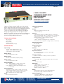
205B rack-mountable high voltage power supplies.
Statements apply to all models in the Series unless
reference is made to specific models. For the
protection of personnel and equipment, it is
essential that this manual be thoroughly read prior
to the installation and application of power.
1.1
PURPOSE OF EQUIPMENT
The series 205B is a family of regulated precision
regulated, locally and remotely variable high
voltage power supplies. They offer exceptional
performance in such critical applications as nuclear
and
electro-optical
instrumentation,
medical
imaging and capillary zone electrophoresis and
precision CRT displays.
1.2
DESCRIPTION
The units are fully enclosed and designed to mount
in a standard 19” rack. A wide range of stable
output voltages from 1kV up to 50 kV is available.
The output voltage is set either by front panel
controls or remote analog voltage or resistance
programming.
Remote analog monitoring is
provided on all models.
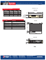
Output polarity reversal is achieved by turning a
polarity switch on the rear panel of 1kV, 3kV and
5kV models. The 10kV and higher output models
have an internal polarity reversing assembly that is
easily accessible in the field. NOTE: in either case,
polarity reversal MUST ONLY BE DONE WHEN
THE HIGH VOLTAGE IS OFF.
The Series 205B units contain a DC power supply
that converts the AC line power to a low voltage DC
and a DC-to-DC converter that generates the high
DC voltage. Low voltage electronics solid-state
analog circuits are placed on plug–in printed circuit
205B Series User’s Manual
2
boards.
The high voltage assembly is fully
encapsulated in silicone rubber for reliable, arcfree, stable operation.
SECTION II: OPERATION
CAUTION! THIS UNIT CAN STORE
HAZARDOUS VOLTAGE. COMPLETELY
DISCHARGE HIGH VOLTAGE AT REAR PANEL
GROUND TERMINAL BEFORE ATTEMPTING
REMOVAL OF THE HIGH VOLTAGE CABLE
2.1
INSTALLATION:
The 205B Series high voltage power supplies
mount in a standard 19” rack.
2.2
INPUT POWER
The input AC line voltage required is
115V/230VAC, ±10%, 50-400Hz, single phase.
The LINE VOLTAGE selector switch on the rear
panel MUST BE SET for either 115VAC or
230VAC BEFORE application of input power.
2.3
VOLTAGE CONTROL
The 205B Series power supply has two modes of
controlling the high voltage outputs available to the
user. Set the PROGRAM CONTROL switch
(S101) on the rear panel to LOCAL for front panel
control. For remote analog control, set the switch
to the REMOTE ANALOG position. The high
voltage output can then be remotely programmed
either from an external voltage source or by using
an external potentiometer. When S101 is in the
REMOTE ANALOG position, the front panel
controls will have no effect on the output voltage
setting.
At all times, regardless of the position of the rear
panel PROGRAM CONTROL switch, the user may
enable or disable the high voltage output by
switching the HV ENABLE switch on the front
panel.
In addition, the voltage and current
monitors are always active. Thus, even when the
PROGRAM CONTROL switch is set to REMOTE
ANALOG control position, the front panel and the
remote analog monitors continue to make voltage
and current readings available.
2.4
POLARITY REVERSAL
The front panel LED display will indicate which
polarity the unit is set for. The display illuminates
even if there is no high voltage output.
CAUTION – LINE INPUT POWER MUST BE
TURNED OFF AND THE HIGH VOLTAGE
SHOULD BE DISCHARGED FULLY BEFORE
PROCEEDING TO REVERSE THE POLARITY.
118124-001-Rev.A