1
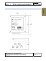
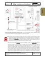
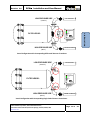
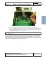
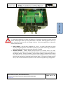
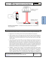
Revision: 3.0 DPM Installation and User Manual 2 ‐ INSTALLATION Deadman Circuit Connection – An example of a Normally Closed Series or ‘Loop’ Deadman wiring configuration. 2.1.8 TEST FUNCTIONALITY Once the DPM has been properly installed, it can be tested for functionality using the following steps; Engage power to the refueling vehicle and verify that the DPM powers‐up properly. Using a restrictor valve on the outlet side of the fuel filter vessel, flow fuel through the system and slowly increase the differential pressure across the filter vessel by closing the restrictor valve. Verify that the DPM shuts the system flow down when the piston gage reaches 22 psid. If the system is does not shut down at 22 psid, disconnect one terminal wire from the pressure transducer and insert a current meter as shown below. Resume fuel flow as described above and verify that there is current flow (in mA) through the transducer. The exact current (mA) that corresponds to a shutdown of 22 psid will vary greatly depending upon the specific transducer range being used. For example, a transducer rated for 0‐25 psid, and with an output of 4‐20 mA will trip the shutdown relay at approximately 18.05 mA. Contact Velcon for the exact current shutdown point of the sensor(s) being used. OVERRIDE – JIG Bulletin No. 58 requires a system shutdown override feature which allows the full range of the pressure transducers to be tested. The DPM provides this override feature through the key switch. Note that because the key switch has a “momentary” actuator, it must be held in position throughout the testing procedure. To use this feature, create a differential pressure rise as described above while engaging the OVERRIDE key Parker Hannifin Corporation, Velcon Filtration Division, 1210 Garden of the Gods Road, Colorado Springs, Colorado, 80907, USA www.velcon.com Page 21 of 27