1
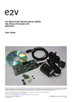
e2v Electrochemical and Pellistor
Gas Sensor Evaluation Kit
ECVQ-EK3
User Guide
Whilst e2v technologies has taken care to ensure the accuracy of the information contained herein it accepts no responsibility for the consequences of any use thereof
and also reserves the right to change the specification of goods without notice. e2v technologies accepts no liability beyond the set out in its standard conditions of sale in
respect of infringement of third party patents arising from the use of tubes or other devices in accordance with information contained herein.
e2v technologies (uk) limited, Waterhouse Lane, Chelmsford, Essex CM1 2QU United Kingdom Holding Company: e2v technologies plc
Telephone: +44 (0)1245 493493 Facsimile: +44 (0)1245 492492
Contact e2v by e-mail: [email protected] or visit www.e2v.com for global sales and operations centres.
© e2v technologies (uk) limited 2010
Template: DF764388A-3
DAS768835AA Version 2, August 2010
109016
IMPORTANT INFORMATION
Before using this product, please read and understand all the instructions and warnings. e2v
technologies does not accept responsibility for damage or injury resulting from failure to follow the
instructions provided.
WARNINGS
• The Evaluation Kit is despatched from e2v technologies in a safe condition. Any unauthorised
modifications may compromise safety and invalidate the warranty.
• The supplied power supply adapter is double insulated, indicated by the
double square symbol. If the Evaluation kit is used with a power supply which
is not double insulated, connect a Protective Earthing Connection to the
Protective Earth terminal on the PCB indicated by the Protective Earth symbol
in case of power supply faults.
• The Evaluation Kit is not certified as intrinsically safe and therefore must not be operated in
potentially flammable or explosive atmospheres.
• Neglecting the above may result in injury or death.
CAUTIONS
• The Evaluation Kit is intended for engineering development, demonstration or
evaluation purposes only. It is not considered to be suitable for general consumer use
and should be handled by people with suitable electronics training.
• The Evaluation Kit contains electrostatic discharge sensitive devices. Always observe
handling precautions.
• The Evaluation Kit and Gas Sensor Devices should always be used within their ratings as given
in their data sheets.
COMPLIANCE
• The Evaluation Kit is intended for engineering development, demonstration or evaluation
purposes only and not for sale on the open market.
• This Evaluation Kit has been tested (but not certified) and deemed to comply with the limits for a
Class B digital device, pursuant to part 15 of the FCC Rules and European Union directives on
electromagnetic compatibility. These limits are designed to provide reasonable protection against
harmful interference when the equipment is operated in a commercial environment. This
equipment generates, uses, and can radiate radio frequency energy and if not installed and used
in accordance with the instruction manual, may cause harmful interference to radio
communications. The user is responsible for providing reasonable protection against interference
with other electronic equipment.
• The Evaluation Kit is not intended for automotive use. It does not contain protection devices
against vehicle supply transient voltages and must not be used for the control of a vehicle, a
vehicular safety system or in a way that may disturb the driver, data bus or statutory devices
fitted to a vehicle.
ENVIRONMENTAL
• e2v technologies declares that the Evaluation Kit complies with EC
directive 2002/95/EC (the RoHS Directive) restricting the use of certain
hazardous materials in electrical and electronic equipment. See section 15
for China RoHS information.
• The Evaluation Kit is classified as Electronic and Electrical Equipment according to
directive 2002/96/EC (the WEEE Directive) and should be segregated from domestic
waste for disposal. Contact your local e2v sales office for disposal instructions.
© e2v technologies (uk) limited 2010
Document subject to disclaimer on page 1
DAS768835AA Version 2, page 2
Contents
1
2
3
4
5
Introduction ......................................................................................................................................... 4
Quick Start Guide ............................................................................................................................... 5
Using the e2v Data Logging Software ................................................................................................ 7
Using HyperTerminal .......................................................................................................................... 9
User Interfaces, Controls and Indicators .......................................................................................... 11
5.1
5.2
5.3
5.4
5.5
5.6
5.7
5.8
5.9
6
Power Supply (SK4, TB1)..............................................................................................................................11
USB Interface (SK5) ......................................................................................................................................11
Electrochemical Sensor Connector (S2) .......................................................................................................11
Pellistor/Thermal Conductivity Sensor Connectors (S1, TB2, TB3) ..............................................................11
User Adjustments (VR1, VR2, LK1) ..............................................................................................................11
LEDS (D1, D2, D3, D4, D5) ...........................................................................................................................11
Reset Switch (SW2).......................................................................................................................................11
JTAG Port (PL1) ............................................................................................................................................12
Expansion Port (PL2).....................................................................................................................................12
Electrochemical Sensors .................................................................................................................. 13
6.1
6.2
6.3
6.4
6.5
7
Biasing ...........................................................................................................................................................13
Output Amplifiers ...........................................................................................................................................13
Setting Zero ...................................................................................................................................................14
Setting Span/Sensitivity .................................................................................................................................14
Minimising Noise on the Electrochemical Sensor Output..............................................................................15
Pellistors and Thermal Conductivity Sensors ................................................................................... 16
7.1
7.2
7.3
8
9
Bridge Circuit .................................................................................................................................................16
Setting Zero ...................................................................................................................................................16
Setting Span/Sensitivity .................................................................................................................................17
Temperature Measurement .............................................................................................................. 17
Alarm Outputs and LEDs .................................................................................................................. 18
9.1
10
11
12
13
14
15
16
Introduction ....................................................................................................................................................18
Digital Inputs ................................................................................................................................. 18
Analog Outputs ............................................................................................................................. 18
Appendix: Evaluation Kit PCB Schematic Diagram ...................................................................... 19
Appendix: Evaluation Kit PCB Parts List ...................................................................................... 20
Appendix: Serial Message Protocol .............................................................................................. 21
Appendix: China RoHS Declaration.............................................................................................. 23
Appendix: Updating the ECVQ-EK3 Embedded Software............................................................ 24
© e2v technologies (uk) limited 2010
Document subject to disclaimer on page 1
DAS768835AA Version 2, page 3
1 Introduction
Thank you for purchasing the e2v Electrochemical and Pellistor Gas Sensors Evaluation Kit.
e2v Electrochemical Gas Sensors are low power devices capable of detecting a range of toxic gases as
well as oxygen. e2v Pellistor and Thermal Conductivity Gas Sensors are higher power devices capable
of detecting a range of flammable gases. Both of these types of devices can be used in many different
applications and this Evaluation Kit from e2v will allow you to experiment and find the most suitable
mode of operation for your particular use.
This Evaluation Kit allows you to:
• Test an e2v electrochemical toxic/oxygen sensor
• Test an e2v pellistor/thermal conductivity gas sensors in one of the following forms:
o Individual bead pairs
o VQ500 series heads
o VQ600 series heads
• Control the electrochemical sensor bias voltage
• Control the pellistor bridge supply voltage
• Calibrate sensors based on a linear response and then monitor gas concentration levels
• Set four alarm levels which drive on-board LEDs and open collector outputs.
• Drive two analogue outputs
• Connect additional circuits to an expansion port
• Log sensor outputs, concentrations and temperature readings using the supplied PC Data Logging
Program.
Contents of Evaluation Kit
•
•
•
•
Evaluation Kit PCB
Mains Power Adapter
USB Lead
CD containing User Manual, e2v Data Logging Software and USB Drivers
Accessories Available
• JAS767906AA – Standard Gas Flow Hood for VQ500 series, Infrared mini-sensors and
electrochemical (non-reactive gas) sensors
• JAS769638AA – Premium Gas Flow Hood recommended for reactive gases e.g. H2S, NO2, Cl2,
ClO2, ETO
© e2v technologies (uk) limited 2010
Document subject to disclaimer on page 1
DAS768835AA Version 2, page 4
2 Quick Start Guide
Warning: Do not connect or plug in any Gas Sensors until instructed!
1. Read the Manual!
a. The supplied CD should auto-run on your PC when inserted into a CD drive.
b. Select ‘User Guide’ from the CD menu.
Before using this product, please read and understand all the instructions and warnings. e2v
technologies does not accept responsibility for damage or injury resulting from failure to follow
the instructions provided!
2. Install the e2v Data Logging Software & USB Drivers on your PC
a. Select ‘Install Data Logging Software and USB Drivers’ from the CD menu.
b. Follow the on-screen instructions.
3. Connect the USB Interface and 9V Power Supply Unit
a. Connect the supplied USB lead from SK5 to a USB socket on your PC
b. Connect the DC output of the Power Supply Unit to SK4
c. Slide the correct pinned mains adapter to the Power Supply Unit to suit the mains sockets
in your country. Plug in the Power Supply Unit. Green LED D5 should be flashing.
d. The PC may take a minute to recognise and initialise the new hardware drivers.
S2
SK5
Electrochem
VR2
VR1
(Biased) 3
1
(Unbiased) 2
LK1
2
TB3
1
Pelistor
2
TB2
1
USB
To PC
D5
SK4
S1
Pellistor
9V DC
From
PSU
4. Run the e2v Data Logging Software
a. Run the program from the start menu.
b. The software will automatically detect which ‘Com Port’ is being used for the USB
connection. (If this does not happen, a Com Port can be manually selected by unticking
‘Automatically search for connected device’ on the ‘Hardware’ menu.
c. The outputs of the Evaluation Kit will now be displayed on the PC monitor.
5. Set-up for Electrochemical Sensors
a. Check if the electrochemical sensor requires a bias (see table over page).
b. For unbiased sensors (0V) set LK1 to position 1-2, otherwise set to 1-3.
c. For biased sensors set LK1 to position 1-3 and adjust VR2 until the correct bias level is
displayed on the PC software (Electrochemical tab).
d. Turn off the power before plugging the sensor into S2
e. Turn the power back on and allow time for the sensor to stabilise.
f. Zero the sensor output current in clean air by pressing ‘Set Zero’ (not required for O2)
g. The sensor output current (nA) is now being correctly displayed.
© e2v technologies (uk) limited 2010
Document subject to disclaimer on page 1
DAS768835AA Version 2, page 5
Quick Start Guide (Continued)
6. Set-up for Pellistor/Thermal Conductivity Sensors
a. Check the bridge supply voltage required from the device datasheet.
b. Turn the bridge supply voltage on and adjust VR1 until the correct bridge supply voltage is
displayed on the PC software (Pellistor tab).
c. Turn off the power before connecting a pellistor/TC type device as follows:
i. Pairs of beads connect into TB2 (compensator) and TB3 (detector). If a trimming
resistor is supplied, connect in parallel with the compensator in TB2.
ii. VQ500 series devices should be plugged into S2.
iii. VQ600 devices should be wired into TB2 and TB3:
• Red lead (compensator)
TB2 Pin 1 (top)
• Yellow lead (common)
TB2 Pin 2 (middle)
• Blue lead (pellistor)
TB3 Pin 3 (bottom)
d. Turn the power back on and allow time for the sensor to stabilise.
e. Zero the bridge output in clean air by pressing ‘Set Zero’.
f. The bridge output voltage (mV) is now being correctly displayed
7. Further Settings – Span Calibration (Measuring the sensitivity)
a. At this stage you will not have correct concentration readings – a calibration is required.
b. For electrochemical devices:
i. Enter the concentration of the calibration gas to be used
ii. Select ‘Measure Sensitivity’ when the calibration gas has been applied
c. For pellistors/thermal conductivity devices:
i. Select the gas type (or manually enter the LEL (Lower Explosive Limit) value)
ii. Enter the concentration of the calibration gas to be used
iii. Select ‘Measure Sensitivity’ when the calibration gas has been applied
d. Note that the calibration assumes a linear response to gas concentration.
Electrochemical Sensor Bias Settings
Sensor
Bias (VSENSE – VREF)
EC4-1-CLO2
EC4-50-CLO2
EC4-50-CL2
EC4-500-CO
EC4-2000-CO
EC4-100-ETO
EC4-200-ETO
EC4-1000-ETO
EC4-1000-H2
EC4-100-H2S
EC4-1000-H2S
EC4-250-NO
EC4-2000-NO
EC4-20-NO2
EC4-20-PH3
EC4-1000-PH3
EC4-20-SO2
EC4-2000-SO2
EC410 (O2)
0V
0V
0V
0V
0V
+300 mV
+300 mV
+300 mV
0V
0V
0V
+300 mV
+300 mV
0V
0V
0V
0V
0V
-600 mV
© e2v technologies (uk) limited 2010
LK1 setting
2-1 .
2-1 .
2-1 .
2-1 .
2-1 .
. 1-3
. 1-3
. 1-3
2-1 .
2-1 .
2-1 .
. 1-3
. 1-3
2-1 .
2-1 .
2-1 .
2-1 .
2-1 .
. 1-3
Document subject to disclaimer on page 1
Circuit Output
Voltage Polarity
Negative
Negative
Negative
Positive
Positive
Positive
Positive
Positive
Positive
Positive
Positive
Positive
Positive
Negative
Positive
Positive
Positive
Positive
Negative
DAS768835AA Version 2, page 6
3 Using the e2v Data Logging Software
Follow the instruction in the Quick Start guide to get the software operating.
The screen should appear as follows:
The USB interface to the Evaluation Kit appears as a virtual ‘Com Port’. When the program is started the
software will automatically detect which ‘Com Port’ is being used for the USB connection. (If this does
not happen, a Com Port can be manually selected by unticking ‘Automatically search for connected
device’ on the ‘Hardware’ menu. The Com Port can be manually selected, using trial and error to identify
the correct one. This is also useful when multiple Evaluation Kits are being used on one PC.
The main screen gives a continuous display of sensor concentrations and temperature. The graph view
can be changed to display all these parameters and also the raw output voltage (pellistors) and current
(electrochemical sensors) in real time. The data can also be saved to a file in ‘csv’ format which can be
read by most spreadsheet programs. Note that many spreadsheets will read a maximum of 65536 lines
(18 hours of data at 1 second intervals). The measurement period can be increased from 1 second to
allow longer tests to be imported. For example, a 10 second measurement period allows 7.5 days of
data to be read into a spreadsheet. Alternatively there is a timer function which can stop data recording
after a set period.
By default, the data logging software autoscales the output readings (i.e. the graph axes expand to show
all of the readings on y and x axes). However, it is possible to change these values in order to ‘zoom in’
on certain readings.
© e2v technologies (uk) limited 2010
Document subject to disclaimer on page 1
DAS768835AA Version 2, page 7
In the Data Logging tab, right-click on the graph to be adjusted and untick ‘autoscale’ for the axis you
want to change:
This stops the axis from automatically expanding.
The values in the axis can then be changed. To do this, double-click on the value at one end of the axis
and adjust using the keypad.
The ‘Pellistor’ tab allows monitoring, control and calibration of pellistor and thermal conductivity sensors
(see section 6). The ‘Electrochemical’ tab allows monitoring, control and calibration of electrochemical
sensors (see section 5).
The ‘Alarms’ tab allows control of the open collector alarm output thresholds (see section 9).
The ‘I/O’ tab gives allows monitoring of digital inputs (see section 10) and setting of analog outputs (see
section 11). It also allows a serial number to be set, useful if using multiple evaluation kits.
The ‘Data’ menu has options to change the displayed units for concentration and temperature.
The ‘Hardware’ menu contains an Update Firmware feature which allows software updates to be loaded
into the microprocessor without having to return the PCB to e2v for reprogramming (see section 16).
© e2v technologies (uk) limited 2010
Document subject to disclaimer on page 1
DAS768835AA Version 2, page 8
4 Using HyperTerminal
The e2v Data Logging software provides full control and monitoring of all the operation modes of the
Evaluation Kit. However users may wish to communicate using the low level protocol. This can be done
manually using a terminal emulation program such as HyperTerminal, or by writing your own PC
software using a language such as Visual Basic or Labview. The low level message protocol is given in
the appendices to this manual.
To communicate with the Evaluation Kit using HyperTerminal use the following procedure:
(Note: the USB Drivers must be installed.)
• Run HyperTerminal from the Windows Start button
• Enter a name and choose an icon:
• Select the correct ‘COM Port’ being used by the USB
Driver:
• Select 9600 Bits per second (Baud), 8 data bits, no
parity, 1 stop bit, no flow control:
© e2v technologies (uk) limited 2010
Document subject to disclaimer on page 1
DAS768835AA Version 2, page 9
• Select File/Properties. Click the Settings tab, then the ASCII Setup button.
Ensure ‘Echo typed characters locally’ is checked:
• Type [WHO] and a response should be received from the Evaluation Kit.
A full list of HyperTerminal commands can be found in Section 14
© e2v technologies (uk) limited 2010
Document subject to disclaimer on page 1
DAS768835AA Version 2, page 10
5 User Interfaces, Controls and Indicators
5.1
Power Supply (SK4, TB1)
The Evaluation Kit requires a 9 V ± 10% power supply. Either connect the supplied 9 V DC mains
adapter to SK4 or a 9 V ± 10% laboratory supply to the terminal block TB1.
The supplied power supply adapter is double insulated, indicated by the double
square symbol. If the Evaluation kit is used with a power supply which is not double
insulated, connect a Protective Earthing Connection to the Protective Earth terminal
on the PCB indicated by the Protective Earth symbol in case of power supply faults.
5.2
USB Interface (SK5)
SK5 is a type B Mini-USB connector for communicating with a PC.
5.3
Electrochemical Sensor Connector (S2)
Electrochemical sensors should be plugged into S2. Before plugging in the sensor, ensure that the
correct bias voltage has already been set up and that the power has then been turned off.
5.4
Pellistor/Thermal Conductivity Sensor Connectors (S1, TB2, TB3)
Pellistor sensors should be plugged in as shown belw. Before plugging in the sensor, ensure that the
correct bridge supply voltage has already been set up and that the power has then been turned off.
• Pairs of beads connect into TB2 (compensator) and TB3 (detector).
If a trimming resistor is supplied, connect in parallel with the compensator in TB2.
• VQ500 series devices should be plugged into S2.
• VQ600 devices should be wired into TB2 and TB3:
o Red lead (compensator)
TB2 Pin 1 (top)
o Yellow lead (common)
TB2 Pin 2 (middle)
o Blue lead (pellistor)
TB3 Pin 3 (bottom)
5.5
User Adjustments (VR1, VR2, LK1)
VR1:
VR2:
LK1:
5.6
Pellistor bridge supply voltage adjust (1.6 V to 4.6 V minimum range)
Electrochemical bias voltage adjust (-700 mV to +350 mV minimum range)
Electrochemical bias 1-2 Unbiased (0 V); 1-3 Biased
LEDS (D1, D2, D3, D4, D5)
D1, D2, D3 and D4 indicate the state of each open collector output on the Expansion Port.
D5 flashes to indicate that the power is on and the software is operating normally.
5.7
Reset Switch (SW2)
Press and release SW2 to reset the microcontroller. This has the same function as removing and
reconnecting the power supply.
© e2v technologies (uk) limited 2010
Document subject to disclaimer on page 1
DAS768835AA Version 2, page 11
5.8
JTAG Port (PL1)
The JTAG Port can be used by engineers wishing to develop their own software for the Evaluation
Board. The socket will connect to a Texas Instruments MSP430 Debug Interface, e.g. MSP-FET430UIF,
for reprogramming and debugging.
TDO
TDI
TMS
TCK
0V
TRST
Unused
5.9
1
3
5
7
9
11
13
2
4
6
8
10
12
14
VCCO
VCCI
Unused
Unused
Unused
Unused
Unused
Expansion Port (PL2)
PL2 is an expansion port allowing connection to additional peripherals. The port provides access to the
input and 3.3 V supplies, four open collector outputs, four digital inputs, two analogue outputs and a
spare UART connection.
3V3 Regulated Power
0V
Input 1 (3V3 logic)
Input 2 (3V3 logic)
Input 3 (3V3 logic)
Input 4 (3V3 logic)
0VA
0VA
Serial RXD (3V3)
0V
1
3
5
7
9
11
13
15
17
19
2
4
6
8
10
12
14
16
18
20
9V Unregulated Power
0V
Output 1 (Open collector)
Output 2 (Open collector)
Output 3 (Open collector)
Output 4 (Open collector)
Analogue Output 1 (0 to 2.048V)
Analogue Output 2 (0 to 2.048V)
Serial TXD (3V3)
Not used
PCB Layout:
© e2v technologies (uk) limited 2010
Document subject to disclaimer on page 1
DAS768835AA Version 2, page 12
6 Electrochemical Sensors
The user is advised to consult the Electrochemical Sensor Application Notes on the e2v website for
information on how an electrochemical sensor operates.
6.1
Biasing
Electrochemical sensors are normally operated in a ‘potentiostat’ circuit which is designed to maintain a
constant bias between the sensing electrode (sometimes call the working electrode) and the reference
electrode. The bias voltage is given is device datasheets as the ‘applied potential’ and is also
summarised in the quick start guide, section 2.
For unbiased sensors, set LK1 to position 1-2.
For biased sensors, set LK1 to position 1-3. VR2 should then be adjusted to set the bias voltage.
Note that the potentiostat circuit (IC8-B) is effectively floating at 2.5 V due to the sensing electrode
connection. The bias voltage on VR2 and LK1 must be considered reference to 2.5 V. Also, the way that
electrochemical sensor bias is defined (VSENSE – VREF) means that the polarity is opposite to that at VR2
and LK1. For example:
For unbiased sensors:
LK1 voltage = 2.5 V (equal to 2.5 V reference)
For +300 mV biased sensors LK1 voltage = 2.2 V (equal to 2.5 V – 300 mV)
For -600 mV biased sensors LK1 voltage = 3.1 V (equal to 2.5 V + 600 mV)
The PC software program displays the actual sensor bias setting, i.e. VSENSE – VREF
The bias voltage should be set-up before the sensor is plugged in.
Turn the power off when plugging in a sensor.
Note that TR5 will clamp the bias to 0 V when the power is turned off. This is useful to keep unbiased
sensors at 0 V so that they will stabilise very quickly when power is re-applied. Biased sensors may
require several hours to stabilise after switch-on. In a gas sensor instrument it is common to maintain
power to the bias circuit via a battery, even when the rest of the instrument is turned off, to achieve a
rapid stabilisation.
6.2
Output Amplifiers
The output of an electrochemical sensor is a current proportional to gas concentration. The range of this
current can be calculated from the sensitivity values given in individual device data sheets.
IC7B is configured as a current to voltage converter with a gain set by R48 + R49 = 3.051k
Therefore the output signal of IC7B (EC_hi_range_out) has the following voltage:
•
EC_hi_range_out
= 3.051 μV/nA
= 3051 V/A
The ADC converter (IC12) is a 16-bit device (65536 steps) using a 5 V reference. Therefore each ADC
step corresponds to 76.29 μV. In terms of sensor output current this is as follows:
•
EC_hi_range_out
= 0.00007629/3051
= 25 nA per ADC step
This is the basic resolution of the Evaluation Kit when using the high range. This range is primarily
intended for operating oxygen sensors which have a very high output. For most other sensors, IC8A
provides a gain of 5 so that its output has the following voltage:
•
EC_lo_range_out
© e2v technologies (uk) limited 2010
= 15255 V/A
= 15.255 μV/nA
Document subject to disclaimer on page 1
DAS768835AA Version 2, page 13
This can be expressed in terms of ADC steps as follows:
•
EC_lo_range_out
= 0.00007629/15255 = 5 nA per ADC step
Using the PC software, the Evaluation Kit can be set to either of the two ranges, or to automatically
switch between them according to the signal level.
Note that the output current is described as positive for most gases (electrons flowing out of the sensing
electrode, although conventional current is actually negative). However for gases which undergo a
reduction in the cell (CLO2, CL2, NO2, O2) the output current is described as negative (electrons flowing
into the sensing electrode, positive conventional current) as shown below. This will correspond to
positive and negative voltage readings accordingly.
Sensor
EC4-1-CLO2
EC4-50-CLO2
EC4-50-CL2
EC4-500-CO
EC4-2000-CO
EC4-100-ETO
EC4-200-ETO
EC4-1000-ETO
EC4-1000-H2
EC4-100-H2S
EC4-1000-H2S
EC4-250-NO
EC4-2000-NO
EC4-20-NO2
EC4-20-PH3
EC4-1000-PH3
EC4-20-SO2
EC4-2000-SO2
EC410 (O2)
6.3
Output Current
Direction
Negative
Negative
Negative
Positive
Positive
Positive
Positive
Positive
Positive
Positive
Positive
Positive
Positive
Negative
Positive
Positive
Positive
Positive
Negative
Setting Zero
To remove any zero offsets, apply clean air to the sensor and press ‘Set Zero’.
For oxygen sensors this is not necessary; in fact it as advisable to press ‘unset zero’ to remove any
previously stored zero settings. If a supply of nitrogen is available, this can be used to set an accurate
zero.
The sensor output current (nA) is now being correctly displayed with the zero offset removed.
6.4
Setting Span/Sensitivity
At this stage you will not have correct concentration readings. The Evaluation Kit allows a simple
calibration to be performed based on a linear response to gas.
Enter the concentration of the calibration gas to be used, then select ‘Measure Sensitivity’ when the
calibration gas has been applied.
On the ‘Data’ menu the concentration units can be changed between %Volume and ppm.
© e2v technologies (uk) limited 2010
Document subject to disclaimer on page 1
DAS768835AA Version 2, page 14
6.5
Minimising Noise on the Electrochemical Sensor Output
Electrochemical cells have very low output signal levels and can be susceptible to noise pickup. The
ECVQ-EK3 has very short track lengths for the sensitive signal to minimise this effect, but the user can
take further steps to improve the output.
•
Turn the pellistor supply off when measuring electrochemical cells.
The pellistor supply uses a switched mode power supply which can cause a small but
measurable level of interference to the electrochemical cell.
•
Use averaging of the output.
The PC software will default to a 10 second rolling average. This can be increased or
reduced as required.
•
Do not operate RF transmitters (e.g. mobile phones) close to the ECVQ-EK3
Bursts of RF energy may cause disturbance of the signal. This effect can also me minimised
by operating the ECVQ-EK3 in a screened enclosure.
© e2v technologies (uk) limited 2010
Document subject to disclaimer on page 1
DAS768835AA Version 2, page 15
7 Pellistors and Thermal Conductivity Sensors
The user is advised to consult the Pellistor Application Notes on the e2v website for information on how
Pellistors and Thermal Conductivity Devices operate.
7.1
Bridge Circuit
Pellistors and Thermal Conductivity Devices are normally operated in a Wheatstone bridge arrangement
as shown below. The compensator and detector beads are balanced using R1 and R2 with some zero
adjustment using R3. Many pellistors are supplied with a separate trimming resistor which is connected
across the compensator bead.
Bridge
Voltage
C
RC
R1
R3
Zero Set
R2
D
0V
VOUT
In the evaluation kit the bridge voltage is set using VR1 covering a range of at least 1.6 V to 4.6 V. The
value of the bridge supply is monitored by the Analog to Digital Converter (ADC) and displayed by the
PC Software.
The bridge voltage should be set up before connecting the pellistor device. Once a correct voltage has
been set, the power should be turned off, then the device plugged in as follows:
•
Pairs of beads connect into TB2 (compensator) and TB3 (detector). If a trimming resistor is
supplied, connect in parallel with the compensator in TB2.
• VQ500 series devices should be plugged into S2.
• VQ600 devices should be wired into TB2 and TB3:
o Red lead (compensator)
TB2 Pin 1 (top)
o Yellow lead (common)
TB2 Pin 2 (middle)
o Blue lead (pellistor)
TB3 Pin 3 (bottom)
7.2
Setting Zero
The evaluation kit does not need resistors R1 and R2 to determine a reference point. This is calculated
as exactly half the bridge voltage. R3 is also not required. To remove any zero offsets, apply clean air to
the sensor and press ‘Set Zero’. This will automatically calculate the zero point.
The zero adjustment can also be removed by pressing ‘Unset Zero’
When the zero has been set, the bridge output (mV) will be correctly displayed by the PC software.
© e2v technologies (uk) limited 2010
Document subject to disclaimer on page 1
DAS768835AA Version 2, page 16
7.3
Setting Span/Sensitivity
At this stage you will not have correct concentration readings. The Evaluation Kit allows a simple
calibration to be performed based on a linear response to gas.
o
o
o
First select the gas type or manually enter the LEL (Lower Explosive Limit) value.
Enter the concentration of the calibration gas to be used.
Select ‘Measure Sensitivity’ when the calibration gas has been applied.
On the ‘Data’ menu the concentration units can be changed between %LEL, %Volume and ppm.
Enter the concentration of the calibration gas to be used, then select ‘Measure Sensitivity’ when the
calibration gas has been applied
8 Temperature Measurement
The Evaluation Kit PCB is fitted with an LM60 temperature sensor IC mounted close to the middle of the
PCB. This gives a voltage output proportional to the ambient temperature and is measured with the
Analog to Digital Converter (ADC) in the microcontroller. The ambient temperature is displayed by the
PC Software.
© e2v technologies (uk) limited 2010
Document subject to disclaimer on page 1
DAS768835AA Version 2, page 17
9 Alarm Outputs and LEDs
9.1
Introduction
Four open collector alarm outputs are provided on the expansion port PL2. Each alarm has an
associated LED (D1-D4) to indicate the status of the alarm output.
To use the open collector outputs, a resistor or other load should be connected to the desired external
voltage. The 9 V input and 3V3 microcontroller supply are also available on the expansion connector for
this purpose.
LED ON
LED OFF
= alarm enabled (open collector driven - low)
= alarm disabled (open collector released – high)
Each of the four alarm outputs can be set to one of the options shown below.
Click ‘Refresh Settings’ to read the current settings from the PCB.
Click ‘Write All Alarm Settings’ to write new alarm settings to the PCB.
The status of the alarms is continually displayed in the ‘Alarms’ tab of the PC Software
Monitor Gas: Each alarm can be set to monitor either the Electrochemical or the Pellistor channel
o Electrochemical channel: the alarm can be set to come on above or below a
threshold of current (nA) or concentration (ppm or %Volume).
o Pellistor channel: the alarm can be set to come on above or below a threshold of
voltage (mV) or concentration (ppm, %LEL or %Volume).
Force ON:
This forces the selected alarm line ON
Force OFF:
This forces the selected alarm line OFF
Follow Input: This forces the selected alarm to track the associated digital input
10 Digital Inputs
Four digital inputs are provided on the expansion port PL2. They can be used by engineers writing their
own application software to run on the Evaluation Kit. The status of each digital input can be viewed on
the ‘I/O’ tab on the PC Software.
11 Analog Outputs
The outputs of two 12-bit digital to analog converters (DACs) are provided on the expansion port PL2.
Each analogue output is buffered by an operational amplifier and can give outputs in the range 0 V (000
hex) to 2.048 V (FFF hex). The analog outputs can be configured on the ‘I/O’ tab as follows:
Write Value:
Fixes the DAC output at a fixed voltage level set on the PC Software
Follow Pellistor:
tracks the value of the Pellistor channel output in mV (adjustable scale)
Note: that a bridge voltage of 0mV corresponds to 1.024V on the output
Follow EC:
tracks the magnitude of the Electrochem channel output in nA (adjustable scale)
© e2v technologies (uk) limited 2010
Document subject to disclaimer on page 1
DAS768835AA Version 2, page 18
12 Appendix: Evaluation Kit PCB Schematic Diagram
© e2v technologies (uk) limited 2010
Document subject to disclaimer on page 1
DAS768835AA Version 2, page 19
13 Appendix: Evaluation Kit PCB Parts List
Item
1
2
3
4
5
6
7
8
9
10
11
12
13
14
15
16
17
18
19
20
21
22
Description
Blank PCB, DPP768583AA
Feet, stick on, black, 11.1mm dia.
Resistor 0603 0.063W 1% 0R0
Resistor 0603 0.063W 1% 10R
Resistor 0603 0.063W 1% 51R
Resistor 0603 0.063W 1% 100R
Resistor 0603 0.063W 1% 470R
Resistor 0603 0.063W 1% 1k5
Resistor 0603 0.063W 1% 1k8
Resistor 0603 0.063W 1% 2k7
Resistor 0603 0.063W 1% 8k2
Resistor 0603 0.063W 1% 10k
Resistor 0603 0.063W 1% 39k
Resistor 0603 0.063W 1% 47k
Resistor 0603 0.063W 1% 100k
Resistor 0603 0.063W 1% 1M
Resistor 0805 0.1W 1% 0R0
Resistor 0803 0.1W 0.1% 25ppm 3k
Resistor 0803 0.1W 0.1% 25ppm 12k
Resistor Variable 1k 0.5W Multiturn
Resistor Variable 500k 0.5W Multiturn
Capacitor Cer. 0603 X7R 50V 10%
10nF
Capacitor Cer. 0603 X7R 50V 10%
100nF
Capacitor Cer. 0603 X7R 16V 10% 1uF
Manufacturer
Any manufacturer
3M
Any manufacturer
Any manufacturer
Any manufacturer
Any manufacturer
Any manufacturer
Any manufacturer
Any manufacturer
Any manufacturer
Any manufacturer
Any manufacturer
Any manufacturer
Any manufacturer
Any manufacturer
Any manufacturer
Any manufacturer
Any manufacturer
Any manufacturer
Bourns
Bourns
Any manufacturer
27
28
29
30
31
32
33
34
35
36
37
38
39
40
41
42
43
44
45
46
47
Capacitor Cer. 0805 X5R 25V 10% 4u7
Capacitor Cer. 1206 X7R 6.3V 10%
10uF
Capacitor Tant. TPSC 25V 10% 10uF
Capacitor Tant. TPSE 16V 10% 100uF
Capacitor Alum. Elec 50V 20% 10uF
Diode LED Green SMD
Diode Schottky 1A 30V SMB
Diode TVS 12V 600W
Diode Pack TVS 6V 500W
Diode Zener 3V9 3W
Transistor NPN SOT23
Transistor JFET P-Chan. SOT23
IC Micro 16 bit 64LQFP
IC Serial Eeprom SO8
IC USB to UART Bridge MLP-28
IC Regulator 3V3 DPAK
IC Reference 2.048V SOT23
IC Op-amp Rail-to-rail I/O SO8
IC Regulator DC/DC LGA50
IC Reference 5.0V SO8
IC ADC 8x16bit 20QFN
IC Temp. Sensor SOT23
Connector Press Mount Socket
48
49
50
51
52
53
54
55
56
Connector SKT DC Power 2.5mm
Connector SKT USB Mini Type B
Connector PLG 14 Way Box Header
Connector PLG 2x10 Way 2.54mm
Connector PLG 1x3 Way 2.54mm
Fuse Polyswitch 500mA Hold
Terminal Block 2 Way
Switch Push button SMD
Crystal SMD 32.768kHz
57
58
59
Link, 0.1” Jumper
Resistor 0603 0.063W 1% 1k0
Resistor 0603 0.063W 1% 120R
Components not fitted:
Capacitor Ceramic 0603
Resistor SMD 0603
Crystal HC49/4H
23
24
25
26
© e2v technologies (uk) limited 2010
Qty
1
4*
3
2
1
3
5
1
1
4
1
4
1
1
6
1
1
2
3
1
1
2
Reference
HW1
HW2, HW3, HW4, HW5
R15, R20, R43
R32, R47
R49
R17, R18, R28
R9, R10, R11, R12, R13
R23
R24
R5, R6, R7, R8
R19
R21, R44, R45, R46
R26
R16
R1, R2, R3, R4, R22, R30
R54
R31
R48, R51
R41, R42, R52
VR2
VR1
C17, C18
Any manufacturer
15
Any manufacturer
10
Any manufacturer
Any manufacturer
2
3
C2, C4, C8, C12, C13, C15, C20, C24,
C25, C26, C27, C28, C30, C32, C65
C9, C10, C11, C16, C35, C36, C37,
C38, C63, C66
C31, C34
C1, C3, C29
TPSC106K025R0500
TPSE107K15R0100
EEE1HA100SP
KP-1608SGC
MBRS130LT3G
SMBJ12A
USB6B1
1SMB5915BT3G
BC846B
MMBFJ177
MSP430F2616TPM
25LC80A-I/SN
CP2102
LD1117DT33C
REF3120AIDBZT
AD8629ARZ
LTM8022EV#PBF
ADR445ARZ
AD7689ACPZ
LM60BIM3
450-1804-01-03-00
1
1
2
5
1
1
1
1
4
1
1
1
1
1
1
3
1
1
1
1
6
C23
C33
C7, C19
D1, D2, D3, D4, D5
D6
D7
D8
D10
TR1, TR2, TR3, TR4
TR5
IC1
IC2
IC3
IC4
IC5
IC6, IC7, IC8
IC10
IC11
IC12
S3
S1 (3 off), S2 (3 off)
1613 14
675031020
1-1634688-4
M20-9981045
M20-9990345
MICROSMD050F
15001/2
KSR221G LFS
MC-146 32.768kHz
+/-20ppm 7.0pF
1
1
1
1
1
1
3
1
1
SK4
SK5
PL1
PL2
LK1
F1
TB1, TB2, TB3
SW2
XT1
AVX
AVX
Panasonic
Kingbright
On-Semi
Any manufacturer
ST-Micro
OnSemiconductor
NXP
Fairchild
Texas **
Microchip
Silicon Labs
ST
Texas
Analog
Linear
Analog
Analog
National
Wearnes
Cambion
Lumberg
Molex
Amp
Harwin
Harwin
Tyco
Elkay
C&K
Epson Toyocom
Part No.
SJ5003BLACK
3296W-1-102LF
3296W-1-504LF
Any manufacturer
Any manufacturer
Any manufacturer
1***
4
1
3
1
1
Document subject to disclaimer on page 1
LK1
R25, R50, R53, R84
R27
C5, C6, C67
R14, R33
XT2
DAS768835AA Version 2, page 20
14 Appendix: Serial Message Protocol
Enquire Status
PCB
Command
[WHO]
Response
[EK3 aa.bb cccc dddd]
Pellistor
Sensor
[EK3 PEL ENQ]
[EK3 PEL aaaa
±bbbbbbbb ±cccc ±dddd
±eeee ffffffff gggggggg
±hh.h iii]
Electrochem
Sensor
[EK3 ECM ENQ]
[EK3 ECM ±aaaa
±bbbbbbbb ±cccccccc
dddddddd ±eeeeeeee
±ff.f ggg hhh]
Analog Out
(DAC)
[EK3 DA1 ENQ]
[EK3 DA1 aaa bbb
±cccccccc]
[EK3 DA2 aaa bbb
±cccccccc]
[EK3 ALa bbb ccc
±dddddddd eee]
[EK3 DA2 ENQ]
aaa
bbb
ccc
ddd
a
b
c
d
Software version
Software checksum
Serial number
Bridge Supply, mV: (hex)
Measured Concentration (ppm*100)(hex)
Bridge Reading (mV *100)(hex)
Sensitivity Reading (span voltage)(mV *100)(hex)
Measured Sensitivity mV/%LEL *100)(hex)
Pellistor LEL Conc (ppm*100)(hex)
Pellistor Span Conc (ppm*100)(hex)
Temperature (C)(decimal to 1dp)
Bridge Supply (ONX, OFF)
Bias Voltage (mV)(hex)
Measured Concentration (ppm*100)(hex)
Sensor Output Current (nA)(hex)
Electrochem Span Concentration (ppm*100)(hex)
Span Current (nA)(hex)
Temperature (C) (decimal to 1dp)
Current Range (RLO = 5nA, RHI = 25nA)
Selected Range (RLO, RHI, RAU)
DAC Setting: MAN, ECM, PEL
DAC output: 000-FFF
Range Maximum (nA if ECM or mV*100 if
PEL)(hex)
Alarm Number (1-4)
Alarm status ONX, OFF
Alarm setting: MAN, FOL, PGT, PLT, EGT, ELT
Alarm threshold: Depends on units (below) (hex)
Threshold Units: LEL, VOL, RAW
•
LEL, Threshold in %LEL*1000000
•
VOL, Threshold in ppm*100
•
RAW (Electrochem) Threshold in nA
•
RAW (Pellistor) Threshold in mV*100
Alarm 1 output ONX, OFF
Alarm 2 output ONX, OFF
Alarm 3 output ONX, OFF
Alarm 4 output ONX, OFF
Digital Input 1 status: 0, 1
Digital Input 2 status: 0, 1
Digital Input 3 status: 0, 1
Digital Input 4 status: 0, 1
[ACK]
[ACK]
[ACK]
[ACK]
[ACK]
[ACK]
[ACK]
aaaaaaaa
Set Pellistor Zero
Unset Pellistor Zero
Set Pellistor Span
Set Electrochem Zero
Unset Electrochem Zero
Set Electrochem Span
Set Pellistor Span Concentration (ppm*100)(hex)
[ACK]
aaaaaaaa
[ACK]
aaaaaaaa
Alarms
(individual)
[EK3 AL1 ENQ]
[EK3 AL2 ENQ]
[EK3 AL3 ENQ]
[EK3 AL4 ENQ]
Alarms (all)
[EK3 AL0 ENQ]
[EK3 AL0 aaa bbb ccc
ddd]
Digital Inputs
[EK3 DIN ENQ]
[EK3 DIN abcd]
[EK3 CAP ZERO]
[EK3 CAP UZER]
[EK3 CAP SPAN]
[EK3 CAE ZERO]
[EK3 CAE UZER]
[EK3 CAE SPAN]
[EK3 CAP SCG
aaaaaaaa]
[EK3 CAE SCG
aaaaaaa]
[EK3 CAP LEL
aaaaaaaa]
No LEL for
Electrochem
[EK3 PEL ONX]
[EK3 PEL OFF]
[EK3 ECM Raa]
[ACK]
[ACK]
[ACK]
Command
[EK3 DA1 aaa]
[EK3 DA2 aaa]
[EK3 DA1 aaa
bbbbbbbb]
[EK3 DA2 aaa
bbbbbbbb]
Response
[ACK]
[ACK]
[ACK]
Calibration
Pellistor
Electrochem
Span Gas
LEL
Sensors
Pellistor Bridge
Electrochemical
Range
Set DAC
Fixed value
Automatic mode
Notes
aa.bb
cccc
dddd
aaaa
±bbbb
±cccc
±dddd
±eeee
ffffffff
gggggggg
±hh.h
iii
aaaa
±bbbbbbbb
±cccccccc
dddddddd
±eeeeeeee
±ff.f
ggg
hhh
aaa
bbb
±cccccccc
a
bbb
ccc
±dddddddd
eee
Set Electrochem Span Concentration
(ppm*100)(hex)
Set LEL Concentration (ppm*100)(hex)
Notes
© e2v technologies (uk) limited 2010
aa
Turn Pellistor Bridge Supply On
Turn Pellistor Bridge Supply Off
LO (use 5nA range), HI (use 25nA range),
AU (Automatically select range)
Notes
aaa
000-FFF
aaa
bbbbbbbb
Sensor to follow (PEL or ECM)
Scale Maximum (mV*100 (PEL) or nA(ECM))(hex)
[ACK]
Document subject to disclaimer on page 1
DAS768835AA Version 2, page 21
Set Alarms
Manual On
(individual: 1-4)
(all together: 0)
Manual Off
(individual: 1-4)
(all together: 0)
Follow digital
inputs
(individual: 1-4)
(all together: 0)
On if Sensor a
value is
Greater Than
threshold
(individual: 1-4)
(all together: 0)
On if Sensor a
value is
Less Than
threshold
(individual: 1-4)
(all together: 0)
System
Serial Number
Invalid
command
Command
[EK3 AL1 MAN ONX]
[EK3 AL2 MAN ONX]
[EK3 AL3 MAN ONX]
[EK3 AL4 MAN ONX]
[EK3 AL0 MAN ONX]
[EK3 AL1 MAN OFF]
[EK3 AL2 MAN OFF]
[EK3 AL3 MAN OFF]
[EK3 AL4 MAN OFF]
[EK3 AL0 MAN OFF]
[EK3 AL1 FOL]
[EK3 AL2 FOL]
[EK3 AL3 FOL]
[EK3 AL4 FOL]
[EK3 AL0 FOL]
[EK3 AL1 aGT ±bbbbbbbb
ccc]
[EK3 AL2 aGT ±bbbbbbbb
ccc]
[EK3 AL3 aGT ±bbbbbbbb
ccc]
[EK3 AL4 aGT ±bbbbbbbb
ccc]
[EK3 AL0 aGT ±bbbbbbbb
ccc]
[EK3 AL1 aLT ±bbbbbbbb
ccc]
[EK3 AL2 aLT ±bbbbbbbb
ccc]
[EK3 AL3 aLT ±bbbbbbbb
ccc]
[EK3 AL4 aLT ±bbbbbbbb
ccc]
[EK3 AL0 aLT ±bbbbbbbb
ccc]
Command
[EK3 SER aaaa]
Invalid command
© e2v technologies (uk) limited 2010
Response
[ACK]
[ACK]
[ACK]
[ACK]
[ACK]
[ACK]
[ACK]
[ACK]
[ACK]
[ACK]
[ACK]
[ACK]
[ACK]
[ACK]
[ACK]
[ACK]
[ACK]
Notes
a
±bbbbbbbb
ccc
P (Pellistor) or E (Electrochem)
Threshold Value
Threshold Units (LEL, VOL, RAW)
a
±bbbbbbbb
ccc
P (Pellistor) or E (Electrochem)
Threshold Value
Threshold Units (LEL, VOL, RAW)
Notes
aaaa
Serial Number (decimal)
[ACK]
[ACK]
[ACK]
[ACK]
[ACK]
[ACK]
[ACK]
[ACK]
Response
[ACK]
[NAK]
Document subject to disclaimer on page 1
DAS768835AA Version 2, page 22
15 Appendix: China RoHS Declaration
有毒有害物质或元素
(Hazardous Substances or Elements)
铅
Lead
(Pb)
零件项目(名称)
(Component Name)
ECVQ-EK3 Evaluation Kit
汞
Mercury
(Hg)
镉
Cadmium
(Cd)
六价铬
Chromium VI
Compounds
(Cr6+)
多溴联苯
Polybrominated
Biphenyls
(PBB)
多溴二苯醚
Polybrominated
Diphenyl
Ethers
(PBDE)
1
印制电路配件
(Printed Circuit Assemblies)
DAS768583AA
Evaluation Kit PCB
O
O
O
O
O
O
2
外接电(线)缆
(External Cables)
E100918
O
O
O
O
O
O
USB Lead
3
电源供应器
(Power Supply Unit)
DAS766693AA
Power Supply Unit
O
O
O
O
O
O
4
文件说明书
(Paper Manuals)
DF769485A
O
O
O
O
O
O
O
O
O
O
O
O
5
光盘说明书
(CD Manual)
DAS768879AA
Quick Start Guide
CD-ROM Manual/Software
O: 表示该有毒有害物质在该部件所有均质材料中的含量均在 SJ/T 11363-2006标准规定的限量要求以下.
O: Indicates that this toxic or hazardous substance contained in all of the homogeneous
materials for this part is below the limit requirement in SJ/T11363-2006.
X: 表示该有毒有害物质至少在该部件的某一均质材料中的含量超出 SJ/T 11363-2006标准规定的限量要求.
X: Indicates that this toxic or hazardous substance contained in at least one of the
homogeneous materials used for this part is above the limit requirement in SJ/T11363-2006
© e2v technologies (uk) limited 2010
Document subject to disclaimer on page 1
DAS768835AA Version 2, page 23
16 Appendix: Updating the ECVQ-EK3 Embedded Software
From time to time e2v may release updates to the PC datalogging software or the embedded software
(firmware) which runs on the ECVQ-EK3 microprocessor. These will normally be available for download
from the e2v website www.e2v.com. To install a new version of embedded software on the ECVQ-EK3,
follow these instructions very carefully:
1. Download the firmware zip file. Unzip and save the text file (ecvq_ek3_.....txt) to the computer
hard drive.
2. Connect up the ECVQ-EK3 evaluation kit to the PC via the USB lead and connect the power.
3. Run the PC software (installed from the supplied CD).
4. Make sure the device is shown as connected.
5. Change the mode to 'Device Setup Mode'.
6. Select the 'Hardware' menu, then 'Update Firmware'.
7. Click 'Start Update'.
8. Select the firmware file (ecvq_ek3_.....txt) on the computer hard drive.
9. Click OK.
**** Warning: Do not disconnect device during update ****
10. When the progress bar has completed, the installation is complete. The new version number will
be shown on the PC screen.
Please read any compatibility notes provided in the readme.txt file supplied in the zip file. It may be
necessary to upgrade to a later version of PC software at the same time.
© e2v technologies (uk) limited 2010
Document subject to disclaimer on page 1
DAS768835AA Version 2, page 24