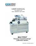
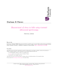
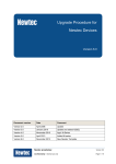
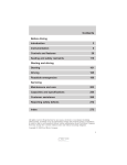
1
FOR YOUR PERMANENT FILE
TESTER MODEL NUMBER:
TESTER SERIAL NUMBER:
For Warranty Claims, Contact CDI Torque Products
at (626) 965-0668.
LIMITED WARRANTY
The CDI Digital Torque TesterTM (DTT) is backed
by a one year warranty. This warranty covers
manufacturer defects and workmanship. The
warranty excludes misuse, abuse and normal
wear and tear. Exclusion is not allowed in some
states and may not apply. This warranty gives
you specific legal rights, and you may have other
rights, which vary from state to state.
IMPORTANT ENVIRONMENTAL NOTES:
1. This equipment may contain hazardous materials which can be
harmful to the environment.
2. Do not dispose of this equipment as municipal waste. Return it
to the distributor or a designated collection center.
Thank you for caring about our environment!
19220 SAN JOSE AVENUE • CITY OF INDUSTRY, CA 91748 • USA
(626) 965-0668
Find other fine torque products at WWW.CDITORQUE.COM
Form 20-2344-CDI
6/2010 Rev. N/C
US and Foreign Patents Pending - Made in USA with US and Global Components
operation manual
Digital Torque TesterTM
(DTT)
important safety
instructions
This manual contains important safety and
operating instructions for the Digital Torque
Tester (DTT).
Read All Instructions
Read, understand and follow all safety
messages and instructions in this manual and
on the test equipment. Safety messages in this
section of the manual contain a signal word, a
three-part message, and, in some instances, an
icon. An icon, when present, gives a graphical
description of the potential hazard.
General Cautions
CDI Torque Products cannot anticipate or
provide safety warnings and cautions to cover
every situation that may be encountered when
operating, servicing or repairing this tester, It
is the responsibility of operators and servicing
technicians to be knowledgeable about the
procedures, tools and materials used, and to
satisfy themselves that the procedures, tools
and materials will not compromise their safety.
Do not attempt to operate this Digital Torque
Tester until you have thoroughly read and
completely understand all instructions and
safety information in this manual. Failure
to comply can result in accidents involving
fire, electric shock or serious personal injury.
Save this manual and review it frequently for
continued safe operation, and use it to instruct
others who may use this tester.
CDI Torque Products is not responsible for
customer modification of test equipment for
applications on which CDI Torque Products was
not consulted.
SAVE THESE INSTRUCTIONS
GENERAL SAFETY
torque tester safety
• Fully engage the direction lever in the correct
position when using ratchets. Never attempt
to test an impact tool or pulse type tool on this
instrument.
• Mount the DTI securely to a heavy bench, wall
or other support structure before applying
torque.
• Do not use the DTT if it makes unusual noises,
has loose parts, or shows any other sign
of damage. Have repairs performed at an
Authorized Service Center before use.
• Do not use chipped, cracked, or damaged
sockets and accessories.
• Do not remove any labels. Replace any
damaged label.
WARNING
Improper use can cause breakage.
• Read instructions before operating.
• Follow manufacturer’s instructions, safety
precautions, and specifications when
operating tools.
Broken equipment can cause injury.
USERS AND BYSTANDERS SHOULD ALWAYS
WEAR EYE PROTECTION
• Flying particles can be discharged when
applying torque.
Flying particles can cause injury.
GEARS
FIRE
Risk of entanglement.
• Keep body parts away from rotating parts.
• Wear a protective hair covering to contain long
hair
and prevent
contact with
moving parts.
XPLOSION
SHOCK
VIBRATE
TRIANGLE
• Do not overreach. Keep proper footing and
balance at all times.
Entanglement can cause injury.
FALLING
GEARS
XPLOSION
VIBRATE
torque tester SAFETY
EYEPROTEC
FACESHLD
FILTMASK
WEARGLV
INFO
WARNING
EARPROT
DONTPULL
HAMMER2
AC Adapter safety
SHOCK
SOLID CIRCLE
FIRE
WARNING
• Be sure ratings for all components, including,
EYEPROTEC drivers
FILTMASK
WEARGLV
FACESHLD
CLOTHING extensions,
adaptors,
and sockets,
match or exceed the torque being applied.
DRWSTEP
TIPOVER
PRYING
• Do
not use EXTENDER
this instrument
with power
switch PRWDRIVR
NO OVERTORQUE
EARPROT
DUSTMASK
OFF. Always turn power switch ON so torque
values are displayed.
• Do not turn the power switch ON with a torque
instrument engaged to tester transducer.
DONOTCR
DRWSTEP
TIPOVER
DONTPULL
EXTENDER
• Be sure the capacity of the DTT matches
or
NO OVERTORQUE
exceeds each application before performing a
procedure.
HAMMER2
HAMRON
• Pull on a wrench handle—do not push—when
tester is mounted horizontally. Adjust stance
to prevent a possible fall.
• Pull on a wrench handle—do not push—when
tester is mounted horizontally. Adjust stance
CAUTION
to prevent a possible fall.
• Do not use extensions, such as a pipe, on a
wrench handle.
Risk of electric shock and fire.
• Do not allow conductive objects to come
in contact with terminals. 120 or 220 volts
present at adapter terminals.
TRIANGLE
•C0For
indoor use only. Do not expose adapter to
MASK NEEDED
rain or snow. Do not use in damp locations.
• Replace
cord immediately.
Return
to
XPLOSION
FALLING defective
GEARS
VIBRATE
qualified service center for replacement.
• Do not use any other type of adapter. Using an
INFO not specifically
C0 MASKfor
NEEDED
SOLID CIRCLE designed
adapter
this unit
may damage tester.
OVER CHILD
•TIPDo
not use an extension cord with adapter.
EYEPROTEC
FILTMASK
FACESHLD
CLOTHING
• Do not use a damaged
adapter.
• Do not disassemble adapter.
• Do not attempt to connect two adapters
together.
TIP OVER CHILD
PRYING
PRWDRIVR
• Do not operate adapter with damaged cord or
plug. Replace immediately.
• Do
not operate
adapter after
it is dropped,
DONOTCR
DRWSTEP
DONTPULL
EXTENDER
NO OVERTORQUE
receives a sharp blow or damaged. Take
the
adapter to an Authorized Service Center.
• Unplug adapter from outlet before
maintenance or cleaning. Turning off tester is
not adequate to avoid hazard.
• Read all instructions and safety messages on
battery and adapter before use.
Electric shock or fire can cause injury.
SW VERSION: 1.X.X
DTT SYSTEM COMPONENTS
introduction
DATE:
Nov
TIME:
“click”
C
B
CHE
03
2009
HR
type11torque
MIN
07
Use the portable DTT to test
wrenches
(adjustable and preset), torque
screwdrivers,60dial
BRIGHTNESS:
indicating and electronic wrenches.
NEXT
The tester features a swivel-neck LCD display with
selectable English or Metric units of measure. 11 models
are available, ranging from 10-100 in.oz. to 60-600 ft.lb.
The DTT displays torque values using a built-in
straingaged transducer with an accuracy of ±0.5% of
TESTER
indicated test value from 10% to 100%DIGITAL
of ratedTORQUE
capacity,
TEST SETUP
in clockwise (CW) and counter-clockwise (CCW) directions.
TGT TORQUE
A
D
Figure 1: Digital Torque Tester (DTT) System Components
A - Digital Torque Tester (DTT)
B - AC Adapter
AC/DC transformer, Voltage Output: 9VDC,
Current 1.66A
C - Battery Pack
Battery holder with 6 AA Battery Cells
D - USB Cable
:
250 FT-LB
Torque Values
SERIAL NUM
110900MAW
Capture and display torque values
in one :of four
selectable modes:
OPERATOR ID : TECH512
• CLICK ADJUST (First Peak)
— Responds to the drop-off in torque caused
NEXT by theNEXT
“click” of an adjustable wrench. FIRST PEAK torque
is measured, captured and displayed (CW or CCW)
just prior to the drop-off, even if click torque is
subsequently exceeded.
• CLICK PRESET (First Peak)
— Responds to the drop-off inENTER
torque
caused by the
TARGET TORQUE VALUE :
“click” of a preset wrench. FIRST PEAK torque
is
250
measured, captured and displayed (CW or CCW)
2 is3
4
just prior to the drop-off, even if click 1torque
subsequently exceeded.
5
6
7
8
• DIAL / ELECT (Peak Hold)
0
BS
— Captures and displays the highest torque 9applied
(CW or CCW) until reset. Use to check dial indicating
MAIN
CLEAR
NEXT
and electronic torque wrenches.
• SCREWDRIVER (Peak Hold)
— Captures and displays the highest torque applied
(CW or CCW) until reset. Use to check torque limiting
screwdrivers.
ENTER WRENCH S/N:
This manual contains general information. 110900
Operating
features and specifications may change without notice.
2
3
4
CDI Torque makes no claims regarding the1suitability
of the information in this manual for diverse
5 user
6
7
8
applications.
A-Z
9
0
BS
POWER SOURCE
CLEAR
NEXT
The power source for the DTT is the supplied
AC Adapter.
The tester can also be operated with the use of the 6 AA
Battery Pack that accompanies the tester.
functional description
TGT TORQUE: 250
FIRST PEAK
0.00
DATA: 25
MAIN MENU
SETUP
A
FT-LB
A - Display
A four digit TFT display for torque readings.
STORE
B - Mounting Plate
Plate for securing tester to mounting surface. Use
four 1/4” diameter bolts.
B
C - Transducer
Female square drive.
D - Battery Access
Battery Pack housing panel. Remove Phillips
B
screw to access Battery Pack.
D
C
E - Power Switch
Rocker switch turns power to tester on and off.
F - Audible Alert
Signal sounds momentarily when:
• Power to tester is initiated,
A is pressed, and
• Anytime a button
• Target Torque is reached.
TGT TORQUE: 250
FIRST PEAK
0.00
DATA: 25
A
G - Swivel
Holds the display for view from any angle.
MAIN MENU
G
H
B
I - USB Jack
Receptacle for uploading torque data to an
external computer.
I
F
STORE
H - AC Adapter Jack
Receptacle (9VDC @ 1.66A max) for continuous
D
AC operation.
E
8.87”
SETUP
FT-LB
B
D
A
Figure 2: Digital Torque Tester (DTT), Front and Side Views
C
specifications
Display
LCD on swivel neck
Display Specifications
Size: 4.7 inch
Resolution: 480 (RGB) X 272
Accuracy
±0.5% of indicated test value from 10% to 100% of
rated capacity
Units of Measurement
ft.lb., in.lb., in.oz., kgcm, Nm and cNm
Operating Temperature
0 - 50°C (32 - 122°F)
Storage
-20 - 70°C (-4 - 158°F)
Dimensions
Width: 10.0”
Height: 15.2”
Depth: 2.5”
Weight
11 lbs
Battery
Six 1 .5V (AA), replaceable
AC Adapter
Input: 100 24OVAC (50-60 Hz)
Output: 9VDC, 1 .66A
Integral Transducer
Full bridge strain gage,
350 ohms, 1500 µE, 3mV/V F.S., 3.3V excitation
transducer range and
display resolutions
DTT built-in transducers provide industry standard
female square drives, and a full bridge strain gage
sensing element.
Contact your CDI Torque representative for service
and/or calibration.
IMPORTANT
Apply torque loads only. Never side-load a wrench
while installed on the tester transducer.
IMPORTANT
Transducers can withstand a torque of 25% over full
range. Do not use the tester if the transducer:
• Does not zero,
• Does not calibrate, or
• Has been over-torqued.
The table below describes minimum and maximum
display ranges.
Part
Number
Square
Drive English
1001-O-DTT 2001-O-DTT
4001-O-DTT
251-I-DTT
501-I-DTT 1001-I-OTT 2502-I-DTT 4002-I-DTT 10002-I-DTT 2503-F-DTT 6004-F-DTT 1/4”
1/4” 1/4” 1/4”
1/4”
1/4”
3/8”
3/8”
3/8”
1/2”
3/4”
Units
10.0-100.0 in.oz.
20.0-200.0 in.oz.
40.0-400.0 in.oz.
2.5-25.0 in.lb.
5.00-50.00 in.lb.
10.0-100.0 in.lb.
25.0-250.0 in.lb.
40.0-400.0 in.lb.
100-1000.0 in.lb.
25.0-250.0 ft.lb.
60.0-600.0 ft.lb.
Metric
7.0-70.6 cNm
14.1-141.2 cNm
28.2-282.4 cNm
2.8-28.25 dNm
5.65-56.50 dNm
11.3-113.0 dNm
28.2-282.5 dNm
45.2-452.0 dNm
113-1130 dNm
33.9-339.0 Nm
81.3-813.6 Nm
setup
TESTER setup
MOUNTING
D
Mount the DTT to a sturdy support before use. Torque
testing procedures may involve hundreds of pounds of
load. Be sure to consider counterweight of the mount
to accommodate torque testing operations and testing
fixtures. Allow enough room around and below the
mount for the wrenches or testing fixtures being used.
Vertical mounting on a wall or heavy pillar is preferred
for most wrench and tool testing as shown in the
illustration below. Use four 1/4” diameter bolts
(torqued to 10 ft.lb.) to insure a secure mount. The DTT
can also be mounted vertically to a horizontal surface
using a right angle bracket.
1. Turn the power switch ON.
C
2. In the MAIN MENU screen, select DTT SETTINGS.
3. In the SYSTEM CONFIGURATION screen, the display
reads:
DATE: MONTH / DAY / YEAR
TIME: HOUR/MINS
A
BRIGHTNESS: 30-100
4. To increment or decrement the DATE/TIME/
BRIGHTNESS elements, select the element and
repeatedly press the UP or DOWN arrows.
NOTE: Press and hold the UP or DOWN arrows to
change the display quickly. The scrolling DATE/
D
TIME elements roll over at both ends for quick
and convenient adjustment of settings.
B
5. Press NEXT to update DATE/TIME/BRIGHTNESS and
return to the MAIN MENU.
8.87”
SYSTEM CONFIGURATION
SW VERSION: 1.X.X
A
8.87”
DATE:
Nov
TIME:
11
CHECKSUM: A1XX
03
HR
BRIGHTNESS:
B
07
MIN
60
Figure 3: Mounting, Dimensions and Right
Angle Bracket
C
A - Mounting Screw (4)
B- Right Angle Bracket
2009
NEXT
Figure 4: System Configuration screen
DIGITAL TORQUE TESTER
0.00
TEST SETUP
FT-LB
TGT TORQUE
:
250 FT-LB
CHANGE
SERIAL NUM
:
110900MAW
CHANGE
OPERATOR ID
:
TECH512
CHANGE
NEXT
NEXT
8.87”
A
tests
TESTING WRENCHES
IMPORTANT
• To avoid damage, be sure the DTT
C model being used
is capable of handling the torque being applied.
B
• Always
position a torque wrench within 15° of
perpendicular to the display housing (Figure 5).
0.00
SW VERSION: 1.X.X
DATE:
Nov
TIME:
11
CHECKSUM: A1XX
03
2009
HR
MIN
07
4. In the SELECT TEST TYPE screen, select either:
BRIGHTNESS:
60
QUICK CHECK (used when verifying torque wrench
readings), or
NEXT
AUDIT (used when testing a torque wrench)
QUICK CHECK MODE
5a. If QUICK CHECK is selected in Step 4, the tester will
display the TEST SETUP screen (Figure 6).
SYSTEM CONFIGURATION
FT-LB
SW VERSION: 1.X.X
CHECKSUM: A1XX
DIGITAL TORQUE TESTER
DATE:
TEST
03 SETUP2009
Nov
TGT TORQUE
: HR
250 FT-LB
TIME:
11
07
BRIGHTNESS:
SERIAL NUM
C
B
OPERATOR ID
MIN
CHANGE
: 60
110900MAW
CHANGE
:
CHANGE
TECH512
NEXT
Figure 5: Wrench Position, Perpendicular to Tester
NEXT
1. Prepare tester for use. For additional information
refer to TESTER SETUP.
NOTE: DTT will ZEROTARE automatically when power
switch is turned ON.
WARNING
Do not turn the power switch ON with a torque
instrument engaged to tester transducer.
2. In the MAIN MENU screen, select TEST.
NOTE: The operator can return to the MAIN MENU at
any step during this procedure by pressing the
MAIN button.
3. In the SELECT WRENCH TYPE screen, select one of
the following options:
Figure 6: Test Setup screen (Quick Check mode)
5b. Press the CHANGE button next to TGT TORQUE to
enter the Target Torque Value and Units desired
DIGITAL TORQUE TESTER
(Figure 7).
TEST SETUP
ENTER TARGET TORQUE
VALUE :
TGT TORQUE
: 250
250 FT-LB
OPERATOR ID
5
:
6
7
TECH512
8
CHANGE
Press UNITS to scroll between
FT-LB,
IN-LB,
9
0
BS
NEXT
IN-OZ, KG-CM, Nm NEXT
and cNm units.
MAIN
CLEAR
NEXT
UNITS
Press NEXT to accept the entry and return to the
TEST SETUP screen.
ENTER TARGET TORQUE VALUE :
ENTER WRENCH S/N:
250
110900
CLICK PRESET
SCREWDRIVER
FT-LB
CHANGEBS to
NOTE: If the incorrect value is entered, press
clear the last1digit2 entered,
3
4 or press CLEAR to
SERIAL NUM
: 110900MAW
CHANGE
delete the entire entry.
CLICK ADJUST
DIAL / ELEC
NEXT
MAIN
1
1
2
2
3
3
4
4
5
5
6
6
7
7
8
8
A-Z
9
9
0
0
BS
BS
CLEAR
CLEAR
NEXT
NEXT
FT-LB
UNITS
Figure 7: Target Torque Value screen
TEST SETUP
TGT
TORQUE
SERIAL
NUM
:
:
250
FT-LB
110900MAW
tests
CHANGE
CHANGE
SERIAL NUM
OPERATOR
ID
:
:
110900MAW
TECH512
CHANGE
CHANGE
5c. Press the CHANGE button next to SERIAL NUM to
ID NEXT
: Number
TECH512 if
enter a OPERATOR
wrench Serial
requiredCHANGE
(Figure 8).
NEXT
NOTE: The WRENCHNEXT
S/N screenNEXT
can be changed from
Numerical (Figure 8) to Alphabetical (Figure 9)
Mode and vice versa by pressing the 0-9 or A-Z
key respectively.
ENTER TARGET TORQUE VALUE :
FT-LB
If the incorrect value is
entered, press BS to clear the
250
TARGET
TORQUECLEAR
VALUE to
: delete
last digit ENTER
entered,
or press
FT-LB the entire
1 2502
3
4
entry.
1
5
2
6
3
7
4
8
The WRENCH S/N screen can be left blank If the Serial
9
0
BS
6 required.
7
8
Number information5 is not
digitMAIN
long
9
0
BS
CLEAR
NEXT
UNITS
alpha.numehc
combination
can
A 12
entered inMAIN
the WRENCH
SIN screen.
CLEAR
NEXT
be
UNITS
Press NEXT to accept the entry and return to the TEST
SETUP screen.
ENTER WRENCH S/N:
110900
ENTER WRENCH S/N:
1110900
2
3
4
1
5
2
6
3
7
4
8
A-Z
5
9
6
0
7
BS
8
A-Z
9
CLEAR
0
BS
NEXT
CLEAR
NEXT
O
P
0-9
Z
S
Z
X
D
C
F
XCLEAR
C
V
G
V
B
H
N
J
B
N
NEXT
M
K
M
BS
L
BS
CLEAR
NEXT
Figure 9: Wrench Serial
Number screen
(Alphabetical Mode)
ENTER OPERATOR ID:
TECH
TEST
NOTE: The OPERATOR ID screen can be changed from
Alphabetical (Figure 10) to Numerical (Figure
11) Mode and ENTER
vice versa
by pressing the A-Z or
WRENCH MAX RANGE : FT-LB
ENTER WRENCH S/N:
0-9 key respectively.
250
110900MAW
ENTER WRENCH MAX RANGE : FT-LB
2502
1 S/N:
4 clear the
ENTER
WRENCH
It the incorrect value is entered,
press3BS to
110900MAW
Q
W
E
R
T
Y
U
I
O
P
last digit entered, or press CLEAR
to delete
the
entire
1
2
3
4
5
6
7
8
entry.
A
S
D
F
G
H
J
K
L
Q
W
E
R
T
Y5 U 9
6 I 0
7 O BS
8P
0-9
Z
X
C
V
B
N
M
BS
The OPERATOR
A
SID screen
D
F can
G be
H left
J blank
K
LIf
9
0
BS
MAIN
CLEAR
NEXT
the Operator Identification
is
not
required.
0-9 Z
XCLEAR
C
V NEXT
B
N
M BS
An 8 digit long alpha-numeric
combination
can
MAIN
CLEAR
NEXT
be entered in the OPERATOR
ID
screen.
CLEAR
NEXT
UNITS
UNITS
Press NEXT to accept the entry and return to the
TEST SETUP screen.
W
PLEASE SET WRENCH TO 50 FT-LB
ENTER OPERATOR ID:
TECH
PLEASE SET WRENCH TO 50 FT-LB
ENTER OPERATOR ID:
TECH
E
R
T
Y
U
I
O
P
A
S
D
F
G
H
J
K
L
W
E
R
T
Y
U
I
O
P
0-9 Z
X
C
V
B
N
M BS
A
S
D
F
G
H
J
K
L
NEXT
0-9 Z
XCLEAR
C
V NEXT
B
N
M BS
NEXT
CLEAR
Q AW SE DR FT GY HU JI KO LP
0-9
A
MAIN
NEXT
CLEAR
Q
ENTER WRENCH S/N:
110900MAW
ENTER WRENCH S/N:
110900MAW
E
R
T
Y
U
I
W
(Figure 10).
Q
Figure 8: Wrench Serial Number screen (Numeric Mode)
Q
1
2
3
4
110900
WRENCH NUM
SIZE :
FT-LB
CHANGE
SERIAL
: 250
110900MAW
CHANGE
5
6
7
8
1
2
3
4
SERIAL NUM
: TECH512
110900MAW
CHANGE
OPERATOR
ID :
CHANGE
A-Z
9
0
BS
5 button
6
7 next
8 to OPERATOR ID to
5d. Press the CHANGE
ID MAIN
: TECH512
CHANGE
enter an OperatorOPERATOR
Identification
number TEST
if required
CLEAR9
A-Z
0 NEXT
BS
NEXT
Figure 10: Operator ID screen (Alphabetical Mode)
ENTER OPERATOR ID:
TEST 1 OF 3
TECH512
DATA: 1
TEST
1 OFOPERATOR
3
ENTER
ID:
1
2
3
4
DATA:TECH512
1
5
1
A-Z
5
TGT TORQUE: 250
0.00
0.00
6
2
7
3
FIRST PEAK
TGT TORQUE: 250
FIRST PEAK
8
4
9
0
BS
6
7
8
MAIN MENU
CLEAR9
A-Z
0 NEXT
BS
MAIN MENU
FT-LB
FT-LB
STORE
STORE
CLEAR ID screen
NEXT
Figure 11: Operator
(Numeric Mode)
PLEASE SET WRENCH TO 150 FT-LB
tests
5e. Press the TEST button to accept all entries and
display the QUICK CHECK test screen (Figure 12).
DIGITAL TORQUE TESTER
TEST SETUP
NOTE: The operator
can return to the TEST SETUP
byFT-LB
pressing the CHANGE
SETUP button.
TGT TORQUEscreen
: 250
SERIAL
NUM
:the
110900MAW
5f. Install
wrench
torque.
OPERATOR ID
:
CHANGE
on the transducer
and apply
5g. PressNEXT
STORE to save
torque measurements in
NEXT
the internal memory. Torque measurements can be
offloaded to a PC using the USB cable. For additional
information refer to Data Offload.
ENTER TARGET TORQUE VALUE :
250
DATA: 25
1
3
4
5
6
DATA: 25
9
7
8
0
BS
MAIN MENU
CLEAR
MAIN
FT-LB
TGT TORQUE: 250
FIRST PEAK
0.00
0.00
2
STORE
FT-LB
Figure 12: Quick Check test screen
SETUP
STORE
AUDIT MODE
6a. If AUDIT is selected
in Step 4, the tester will display
DIGITAL
ENTER WRENCH
S/N:TORQUE TESTER
Audit Mode
the
TEST
SETUP
screen (Figure 13).
110900
TEST SETUP
WRENCH
SIZE
1
2
3:
CHANGE
250
4 FT-LB
DIGITAL TORQUE TESTER
SERIAL
NUM
5
6
7: 110900MAW
8
TEST SETUP
CHANGE
A-Z SIZE
9 ID 0:
OPERATOR
WRENCH
BS FT-LB
TECH512
250
CHANGE
MAIN
:NEXT
110900MAWTEST
CHANGE
SERIAL
CLEARNUM
OPERATOR ID
:
1
2
Q
W
E
R
T
Y
U
I
ENTER WRENCH MAX
5
6
A
S
D
F
G
H250 J
X
C
V 1B
CHANGE
TECH512
Press NEXT to accept the entry and return to the
TEST SETUP screen.
ENTER WRENCH MAX RANGE
250
MAIN
:
1
2
3
4
5
6
7
8
9
0
BS
CLEAR
FT-LB
NEXT
UNITS
Figure 14: Wrench Max Range screen
NOTE: For intormation on how to update
SERIAL NUM, and
PLEASEID;
SET WRENCH TO 50 FT-LB
OPERATOR
please reter to Steps 5c & 5d.
Press TEST to accept all entries.
NEXT
TEST
ENTER
WRENCH
MAX RANGE
: FT-LB
Figure
13:
Test
Setup
screen (Audit
Mode)
ENTER
WRENCH
S/N:
110900MAW 250
Z
:
Press UNITS to scroll between FT-LB, IN-LB,
IN-OZ, KG-CM, NmMAIN
and cNm units.
TEST
CHANGE
TECH512
MAIN
0-9
WRENCH
SIZE : value
250 FT-LB
CHANGEBS to
NOTE: If
the incorrect
is entered, press
clear the last digit entered, or press CLEAR to
SERIAL NUM
: 110900MAW
CHANGE
delete
the entire
entry.
TGT TORQUE:
250
FT-LB
FIRST PEAK
SETUP
NEXT
UNITS
MAIN MENU
TEST SETUP
OPERATOR ID
CHANGE
TECH512
6b. Press the CHANGE button next to WRENCH SIZE to
enter the Full Scale torque and Units of the wrench
being calibratedDIGITAL
(Figure TORQUE
14). TESTER
9N
2
3
4
O
P
RANGE :
7
8
K
L
0M
3
BS
BS
4
FT-LB
TEST 1 OF 3
TGT TORQUE: 250
DATA: 1
FIRST PEAK
0.00
FT-LB
ENTER WRENCH S/N:
250
110900MAW
DIGITAL TORQUE TESTER
TEST 1 OF 3
tests
Q
1 TEST
2 SETUP
3
4
WRENCH
E ENTER
R
T
Y S/N:
U
I
O
P
WRENCH SIZE : 250 FT-LB
110900
5
6 user
7 to8set
6c. The tester
will prompt
A
S
D
F
G
H
J
K
L
Full Scale
(Figure
15).
SERIAL
NUM
1
2
3: 110900MAW
49
0
BS
0-9 Z
X
C
V
B
N
M BS
W
CHANGE
wrench to 20% of
CHANGE
OPERATOR
CHANGE
For example:
5
6 ID 7: TECH512
8
MAIN
CLEAR
NEXT
UNITS
CLEAR
NEXT(Step 6b) is entered as 250 FTIf WRENCH
MAX RANGE
A-Z
9
0
BS
MAIN
LB, the DTT
will
prompt
user toTEST
set wrench to 50 FT-LB.
CLEAR
NEXT
Press NEXT.
For example: MAIN MENU
STORE
If WRENCH MAX RANGE (Step 6b) is entered as 250 FTLB, the DTT will prompt user
to set wrench to 150 FT-LB.
NEXT
PLEASE SET WRENCH TO 150 FT-LB
WRENCH
E ENTER
R
T
Y S/N:
U
I
O
P
2
3
4
110900MAW1
A
S
D
F
G
H
J
K
L
5
6
7
8
Q 0-9W Z E X R C T V Y B U N I M O BSP
9
0
BS
A
S
D
F
G
H NEXT
J
K
L
CLEAR
NEXT
MAIN
0-9 Z
X
C
V CLEAR
B
N
M NEXT
BS
W
TEST 1 OF 3
TGT TORQUE: 250
DATA: 1
FIRST PEAK
0.00
NEXT
UNITS
Figure 15: Wrench Set prompt screen
CLEAR
0.00
6e. The tester will prompt user to set wrench to 60% of
FT-LB
Full Scale (Figure 17).
Press NEXT.
PLEASE
SET WRENCH
TO 50 FT-LB
ENTER
OPERATOR
ID:
ENTER WRENCH MAX RANGE : FT-LB
TECH
250
Q
TGT TORQUE: 250
DATA: 1
FIRST PEAK
PLEASE SET WRENCH TO 50 FT-LB
Figure 17: Wrench Set prompt screen
MAIN MENU
NEXT
FT-LB
STORE
6d. The display will change to the 20% test screen
(Figure 16).
6f. The display will change to the 60% test screen
(Figure 18).
ENTER OPERATOR ID:
Install TEST
the
wrench
the transducer.
1 PLEASE
OF 3 on
TORQUE:
SET WRENCH TOTGT
50 FT-LB
1 OF 3 on the transducer.
TGT TORQUE:
InstallTEST
the wrench
TECH512
DATA: 1
0.00
250
FIRST PEAK
ENTER
ID:
The screen
display
a test counter which indicates
1 will
2OPERATOR
3
4
TECH
the number
of times the user must apply torque at the
5
6
7
8
20% setting:
FT-LB
Q
W
ETEST
R 1 of
T 3Y
U
I
O
P
A-Z
9
0
BS
A
S TEST
D 2F of 3
G
H
J
K
L
MAIN MENU
STORE
TEST
3 of 3 NEXTNEXT
CLEAR
0-9
Z
X
C
V
B
N
M
BS
Apply torque until the wrench reaches 50 FT-LB.
CLEAR
Then press
STORE toNEXT
advance the test counter.
Repeat procedure until counter reaches 3 of 3.
PLEASE SET WRENCH TO 150 FT-LB
TEST 1 OF 3
TGT TORQUE: 250
DATA:
1 OPERATOR ID:
ENTER
TECH512
FIRST PEAK
1
5
A-Z
0.00
2
3
4
6
7
8 NEXT
9MAIN0MENU
BS
FT-LB
STORE
Figure 16: 20% torque test screen
CLEAR
NEXT
0.00
150
DATA: 3
FIRST PEAK
PLEASE SET WRENCH TO 150 FT-LB
The screen will display a test counter which indicates
the number of times the user must apply torque at the
FT-LB
60% setting:
TEST 1 of 3
TEST 2 of
3 MENU
MAIN
STORE
TEST 3 of 3
Apply torque until the wrench
NEXT reaches 150 FT-LB.
Then press STORE to advance the test counter.
Repeat procedure until counter reaches 3 of 3.
The stored data will also accumulate in the primary
store box. PLEASE SET WRENCH TO 250 FT-LB
TEST 1 OF 3
TGT TORQUE: 150
DATA: 3
FIRST PEAK
0.00
NEXT
MAIN MENU
FT-LB
STORE
Figure 18: 60% torque test screen
TEST 1 OF 3
DATA: 3
TGT TORQUE: 150
0.00
testsFIRST
PEAK
6g. The tester will prompt user to set wrench to 100%
FT-LB
of Full Scale (Figure 19).
For example: MAIN MENU
STORE
If WRENCH MAX RANGE (Step 6b) is entered as 250 FTLB, the DTT will prompt user to set wrench to 250 FT-LB.
Press NEXT.
6i. At the end of the test sequence, the tester will
return to the TEST SETUP screen in order to begin a new
test sequence. To continue the test sequence in the
CCW direction, press TEST.
6j. Stored torque measurements can be offloaded to
a PC using the USB cable. For additional information
refer to Data Offload.
Data Offload
Torque measurements are stored in the internal
memory everytime the STORE button is pressed during
the testing procedure. DTT tester allows users to off
load saved data to a PC via the USB cable.
PLEASE SET WRENCH TO 250 FT-LB
To retrieve saved data:
NEXT
Figure 19: Wrench Set prompt screen
6h. The display will change to the 100% test screen
(Figure 20).
Install the wrench on the transducer.
The screen will display a test counter which indicates
the number of times the user must apply torque at the
100% setting:
TEST 1 of 3
TEST 2 of 3
TEST 3 of 3
Apply torque until the wrench reaches 250 FT-LB.
Then press STORE to advance the test counter.
Repeat procedure until counter reaches 3 of 3.
The stored data will also accumulate in the primary
store box.
TEST 1 OF 3
TGT TORQUE: 250
DATA: 9
FIRST PEAK
0.00
MAIN MENU
STORE
Figure 20: 100% torque test screen
- Connect the USB cable between the DTT and PC
USB ports.
- Turn the DTT switch ON.
- On the PC, double click the DTTDATA.CSV file
located in MY COMPUTER \ DTT.
- The DTTDATA file will contain the following
information (Figure 21):
TIME
DATE
OPERATOR ID
WRENCH SERIAL NUMBER
ACTUAL TORQUE
TARGET TORQUE
ERROR (%)
UNITS
To delete saved data:
- Deleted the DTTDATA.CSV file located in MY
COMPUTER \ DTT
FT-LB
Figure 21: Stored Data Information