1
TRIFLEXWindows
Chapter 5
Table of Contents
TRIFLEXWindows User Manual
Introduction to TRIFLEXWindows ...................................................... Chapter 1
Tutorial ................................................................................................. Chapter 2
Data Entry ............................................................................................. Chapter 3
Data Preparation .................................................................................... Chapter 4
Use of Restraints ................................................................................... Chapter 5
5
Restraints.................................................................................................... 3
5.1.1 What Is A Restraint? ....................................................................... 3
5.1.2 Use of Restraints to Inhibit Movements........................................... 4
5.1.3 Use of Restraints to Impose Movements.......................................... 6
5.1.4 How To Use Restraints To Impose Variable or Constant Loads....... 7
5.1.5 How to Represent Wind Loads........................................................ 8
5.1.6 Use of Restraint Flexibility to Simulate Friction.............................. 8
5.1.6.1
Friction Sample Problem
9
5.1.7 Use of Restraints to Simulate Pressure Thrust ................................. 9
5.1.8 Restraints on Various Piping Data Point Types ............................... 9
5.1.8.1
Anchors
9
5.1.8.2
Bends
10
5.1.8.3
Joints, Valves, and Flanges
10
5.1.8.4
Expansion Joints
11
5.1.8.5
Runs
11
5.1.9 One-Directional and Two-Directional Restraints ........................... 11
5.1.9.1 Two-Directional Restraints
12
5.1.9.2 One-Directional Restraints
13
5.2
Manual Selection of Spring Hangers ............................................. 13
5.2.1 Manual Selection
5.3
13
Spring Hanger Output Report........................................................ 16
1
TRIFLEXWindows
5.4
Chapter 5
Expansion Joints ........................................................................... 17
TRIFLEXWindows Theory Manual
TRIFLEX Output ................................................................................... Chapter 6
Rotating Equipment Compliance Reports ............................................... Chapter 7
TriflexWindows Piping Code Compliance Reports ............................ Chapter 8
TriflexWindows Dynamic Capabilities................................................. Chapter 9
Related Engineering Data ........................................................................Appendix
2
TRIFLEXWindows
5
Chapter 5
Restraints
This section is a reference book of engineering solutions to actual piping problems. Restraints
and their use are explained in detail. A rigid or flexible restraint is defined, and a detailed
explanation is provided for when and how to use the proper type of restraint to simulate
numerous piping situations.
The input for restraints is found either in the Restraint Tab window, which can be found on all
components except Anchor, Expansion Joint and Release Element
5.1.1 What Is A Restraint?
A restraint is an attachment to a piping data point (Run, Bend, Joint, Valve, or Flange) which
causes an external action (force, moment, deflection or rotation) to be applied to the piping
system. It can also limit or prevent the free translation or rotation of the piping. Characteristics
of restraints are:
1)
A restraint may be translational or rotational and one-directional or
two-directional.
2)
A restraint may have a spring constant only, or it may have a spring constant and
an initial load.
3)
It may be rigid (no flexibility and/or initial load) with no initial movement.
4)
It may be rigid with an initial movement.
In TRIFLEX, a restraint has one degree of freedom and can act along or about only one axis
(known as a degree of freedom). For example, a Y translational Restraint acts only along the
vertical axis and does not resist X or Z deflections or X, Y, or Z rotations. Restraints may be
along or about the global or local axis system.
In TRIFLEX, two types of restraints are used: rigid and flexible.
Rigid -These include all supports, guides, stops, and other fixtures which restrict
movement (anchors not included).
Flexible -These include supports which impose varying or constant loads on the piping
system. Two-directional rigid or flexible restraints may act along or about any axis. The
restraint axis may be skewed in any manner with respect to the global axis system.
5.1.2 Use of Restraints to Inhibit Movements
3
TRIFLEXWindows
Chapter 5
When a rigid support or guide is used to prevent the pipe from moving along an axis or from
rotating about an axis at a data point, TRIFLEX rigidly restrains the pipe along or about that
axis. Rigid restraints acting along the X-, Y-, or Z-axis with no imposed initial movements, may
be double- acting or one-directional. A two-directional restraint will restrain movement in both
the positive and the negative directions along its axis. One-directional restraints will resist
movement in either the positive axis direction or the negative axis direction, but not both. Refer
to Section 5.1.9 for a discussion of one-directional restraints.
The forces and moments printed in the TRIFLEX output reports are the loads exerted on the
piping system by restraints. The direction of the load action may be determined by the sign of
the load. For example, a Y-axis restraint with a Y-axis force is indicated in the TRIFLEX
Output Report as 5000 pounds. The absence of a sign always means positive. This force is
being exerted by the restraint on the piping system. The piping system is pushing down on the
restraint causing a reaction of 5000 pounds.
If a rigid, double-acting restraint, acting along the Y-axis is input (by entering Y in the Rigid
Restraint field of the detail portion of the data entry screen), the following considerations are
applicable:
1)
If the restraint exerts an upward force on the pipe (i.e., the pipe tries to move
downward):
a)
The axis action in the PIPING RESTRAINT DESCRIPTION report will be Y.
The absence of a plus or minus sign indicates that the restraint is double-acting
along the Y-axis. The Initial Movement and the Initial Load columns both
contain zeros (0). The Spring Rate column contains RIGD to indicate that
TRIFLEX considers the restraint to be totally rigid.
b)
The DY deflection in the RESTRAINT DEFLECTIONS AND ROTATIONS
report is 0.000. A magnitude of 0.000 indicates that the pipe was not allowed to
move at all along the Y-axis.
c)
The F-Y force in the RESTRAINT FORCES AND MOMENTS ON SYSTEM
report is positive. The pipe is pushing down on the restraint.
2)
If the restraint exerts a downward force on the pipe (i.e., the pipe tries to move
upward):
a)
The axis action in the PIPING RESTRAINT DESCRIPTION report is Y. The
Initial Movement and the Initial Load columns both contain zeros. The Spring
Rate column contains RIGD to indicate that TRIFLEX considers the restraint to
4
TRIFLEXWindows
Chapter 5
be totally rigid.
b)
The DY deflection in the RESTRAINT DEFLECTIONS AND ROTATIONS
report is zero. A magnitude of 0.000 indicates that the pipe was not allowed to
move at all along the Y-axis.
c)
The F-Y force in the RESTRAINT FORCES AND MOMENTS ON SYSTEM
report is negative at data point 10. The negative sign indicates that the force acts
on the pipe in a negative Y direction. The pipe is trying to lift off of the restraint.
If a rigid one-directional (single-acting) restraint acting along the Y- axis is input in the plus Y
sense (by entering +Y in the Rigid Restraint field), the following considerations are applicable:
1)
If the restraint exerts an upward force on the pipe (i.e., the pipe tries to move
downward):
a)
The axis action in the PIPING RESTRAINT DESCRIPTION report will be +Y.
The plus sign indicates that the Restraint is one-directional and acts in the positive
direction along the Y-axis. The Spring Rate column of this same report will
contain RIGD, to indicate that TRIFLEX is considering the restraint as totally
rigid.
b)
The DY deflection in the RESTRAINT DEFLECTIONS AND ROTATIONS
report is zero. A magnitude of 0.000 indicates that the pipe was not allowed to
move at all along the Y-axis.
c)
The F-Y force in the RESTRAINT FORCES AND MOMENTS ON SYSTEM
report will be positive at data points 105 and 205. The absence of a minus sign
indicates that the force acts on the pipe in the positive Y direction. The pipe is
pushing down on the restraint.
2)
If the pipe moves upward (i.e., the pipe moves away from the restraint):
a)
The axis action in the PIPING RESTRAINT DESCRIPTION report is +Y. The
plus indicates that the restraint is one-directional and acts in the positive direction
along the Y-axis. The Spring Rate column of this same report will contain FREE
(d.p. 900 above) to indicate that TRIFLEX is taking the Restraint as totally
flexible.
b)
The DY deflection in the RESTRAINT DEFLECTIONS AND ROTATIONS
report is positive.
c)
The F-Y force in the RESTRAINT FORCES AND MOMENTS ON SYSTEM
report is zero.
5
TRIFLEXWindows
Chapter 5
5.1.3 Use of Restraints to Impose Movements
When a rigid support or guide is used to force deflection along an axis, or rotation about an axis
of a pipe, TRIFLEX rigidly restrains the pipe along or about the designated axis while forcing
the pipe to deflect or rotate to the position described by the user's initial movement data.
Restraints with imposed initial movements are double-acting and must be rigid. An exception is
the use of limit stops with initial movement. See the discussion on limit stops in this section, on
the use of limit stops. The force and moment printed in the RESTRAINT FORCES AND
MOMENTS ON THE SYSTEM report is the actual load exerted on the piping system by the
restraint as a result of the analysis conditions, the restraint's rigidity and the imposed movement.
Movements may be imposed with the use of skewed restraints.
If the restraint is a Y restraint with a 1/4 inch upward movement: input the 0.25" movement in
the Restraint Sub Detail Window:
1)
If the restraint exerts an upward force on the pipe (i.e., the pipe tries to move
downward):
a)
The Axis Action in the PIPING RESTRAINT DESCRIPTION report is Y (d.p.
500 above). The Initial Movement column contains 0.250. The absence of a
minus sign indicates that the movement entered was in the positive direction.
The Initial Load column contains a zero to indicate that no initial load is
considered. The Spring Rate column contains RIGD to indicate that TRIFLEX
considers the restraint to be totally rigid.
b)
The DY deflection in the RESTRAINT DEFLECTIONS AND ROTATIONS
report is 0.250. The absence of a minus sign indicates that the movement of the
pipe was in the positive Y direction. The magnitude of 0.250 indicates that the
pipe moved upward 0.250 inches and was held there by the restraint.
c)
The F-Y force in the RESTRAINT FORCES AND MOMENTS ON SYSTEM
report is positive. The absence of a minus sign indicates that the restraint acts on
the pipe in the positive Y direction. The positive force indicates the magnitude of
the force exerted on the pipe to prevent the pipe from moving more than 0.250
inches above the original location.
2)
If the restraint exerts a downward force on the pipe (i.e., the pipe tries to move
upward more than 1/4 inches and away from the restraint):
a)
The axis action in the PIPING RESTRAINT DESCRIPTION report is Y (data
point 714 above). The absence of a plus or minus sign indicates that the restraint
is double-acting along the Y-axis. The Initial Movement column contains 0.250.
The absence of a minus sign indicates that the movement entered was in the
positive direction. The Initial Load column will contain a zero to indicate that no
6
TRIFLEXWindows
Chapter 5
initial load is considered. The Spring Rate column contains RIGD to indicate that
TRIFLEX considers the restraint to be totally rigid.
b)
The DY deflection in the RESTRAINT DEFLECTIONS AND ROTATIONS
report is 0.250. The absence of a minus sign indicates that the pipe moved in the
positive Y direction. The magnitude of 0.250 indicates that the pipe moved
upward 0.250 inches and was held there by the restraint.
c)
The F-Y force in the RESTRAINT FORCES AND MOMENTS ON SYSTEM
report is negative. The negative sign indicates that the restraint acts on the pipe in
the negative Y direction. The negative force indicates the magnitude of the force
exerted on the pipe to prevent it from moving more that 1/4 inch upward.
5.1.4 How To Use Restraints To Impose Variable or Constant Loads
Flexible restraints are required to impose a force or a moment on the piping system at a data
point location. The restraint may be free with a stiffness of one (1) lb/in or one (1) in-lb/deg. A
restraint can also have any stiffness less than total rigidity.
To input a non-rigid restraint, the user should open the Restraints Window by striking
from either the Node Detail window or the Physical Properties window of the Node Input screen.
(Note: function key usage is defined at the bottom of the input screen, so you should see "
: Restraints" at the bottom of your screen. If you do not, press
until it appears). The Restraints window permits the specification of a wide variety of non-rigid
restraints.
To model a constant effort spring support acting vertically, enter the operating load in the Load
field under Existing Spring or in the Y field of the Force column under Restraint at the bottom
left of the screen.
The latter example will place a force of 2000 lbs. along the Y-axis. The form will accomplish
the same result. For additional information on a constant effort spring support, see Section 4.2
Sample Coded Data Points.
To model a variable spring support acting vertically: Enter both the installed load, and a stiffness
equal to the spring rate for the spring hanger selected.
Thus, using the Load and Rate fields under the label Existing Spring, or by using the Y Force
and Stiffness fields under the label RESTRAINTS will accomplish the same results.
If you do not know the installed load or the spring rate required, enter Y in the SPRING? field
followed by the load variation in %, and TRIFLEX will select a spring. Horizontally-acting
springs can be modeled by using the X Force and Z Force fields, followed by the load and spring
rate. For additional information on variable spring supports, see Section 4.2 Sample Coded Data
Points. A detailed discussion of Spring Support Selection Techniques follows in Section 5.2
entitled Manual Selection of Spring Hangers and Section 5.3 entitled Automatic Spring Hanger
Sizing.
7
TRIFLEXWindows
Chapter 5
5.1.5 How to Represent Wind Loads
To represent a wind load, you can:
1)
2)
3)
use the TRIFLEX wind load or wind speed capability
use the TRIFLEX uniform load capability
use a concentrated load acting in the direction of the wind at data points
throughout the portion of the piping system receiving the wind load
The concentrated load should be located at the centroid of the projected area that the restraint
represents. The load should be equal to the wind force per square foot multiplied by the number
of square feet of projected area multiplied by a shape factor.
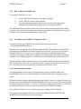
5.1.6 Use of Restraint Flexibility to Simulate Friction
To simulate friction using TRIFLEX, the friction field has been provided on
: Restraints Specifications window.
In this field, the user specifies the coefficient of static friction. The coefficient is usually taken
from engineering handbooks for whatever materials are involved. For dry steel on dry steel a
typical coefficient is 0.40. However, if a piping system were to be coded with the correct
coefficient, the system would be under complete static friction at all points which is an extreme
condition. For modelling purposes, a coefficient of 1/2 the standard value is often times used.
Analysts normally consider a piping system to be frictionless, which is not true, but friction can
safely be ignored in most cases. To consider a system as completely frictional is also not a true
case. The analyst must use his judgement on when to utilize friction effects.
5.1.6.1 Friction Sample Problem
The sample problem in this section was analyzed using frictional restraints which resist
horizontal pipe motion due to thermal expansion, internal pressure thrust, and piping system
weight.
Frictional restraints have been placed at locations where friction forces are expected to resist pipe
motion. Note in the PIPING RESTRAINT DESCRIPTION report that each friction restraint has
been broken into three restraints: +Y, X and Z. Resistance to pipe motion is taken care of by the
two horizontal restraints. These restraints are generated by the TRIFLEX program.
The coefficient of friction of .15 is listed as well as the resultant percent of friction.
The support frictional and normal forces are shown in the RESTRAINT FORCES AND
MOMENTS ON SYSTEM report on the next page.
8
TRIFLEXWindows
Chapter 5
5.1.7 Use of Restraints to Simulate Pressure Thrust
To simulate pressure thrust in an Expansion Joint, a positive and negative restraint should be
entered to act outwardly away from the bellows, along the axis of the pipe on either side of the
Expansion Joint. Both restraint initial loads should be equal to the effective area of the
Expansion Joint multiplied by the pressure. For examples of pressure thrust coding, see Section
4.2 entitled "Sample Coded Data Points". TRIFLEX will automatically calculate the pressure
thrust and direction when given the effective cross sectional area of the expansion joint.
5.1.8 Restraints on Various Piping Data Point Types
Restraints may be placed on Run, Bend, Joint, Valve, and Flange Data Point Types only.
5.1.8.1 Anchors
An anchor has six possible degrees of freedom or rigidity. Three are in translation and three are
in rotation. An anchor is similar in function to the application of six restraints at the same
location. Anchors are assumed to be rigid unless non-zero stiffnesses are specified as the
translational and/or rotational stiffness. This can be done using the fields SCX, SCY, SCZ,
(translational stiffness) and RCX, RCY, RCZ (rotational stiffness) in the Anchor Detail window.
An imposed movement at an anchor may be specified along or about any or all axes. Stiffnesses
and movements may be coded along or about the same axis. This feature will help to accurately
model your piping system. Anchors restrict movement to the extent defined. They act in both the
positive and the negative sense.
Initial loads are not permissible on anchors. However, loads may be specified at the same
location as an anchor by using a zero-length run data point. An anchor may be used to model a
two-directional restraint. To model a rigid Y restraint, an anchor should be specified with the
anchor stiffness fields set as follows: SCX=1, SCY=0, SCZ=1, RCX=1, RCY=1, RCZ=1. This
allows freedom in all directions except along the Y-axis by specifying very low stiffnesses along
and about all axes except Y, where it is treated as infinite stiff. Because all anchor axes are
two-directional, this model of a Y restraint may only be two-directional.
For an in-depth discussion of single-acting or one-directional restraints versus double-acting
restraints, see Section 5.1.9 entitled "One-Directional and Two-Directional Restraints".
5.1.8.2 Bends
Bends may have as many as six restraints specified on them at any point on the bend centerline.
Both rotational and translational restraints may be applied to bends. Any or all of these restraints
may be rigid, with or without restraint movements, or may be flexible, with or without initial
9
TRIFLEXWindows
Chapter 5
restraint loads.
The field N/M/F in the Bend Detail window will control the placement of restraints on bends.
Entering N will place the restraint on the near weld point of the bend. Entering F will place the
restraint on the far weld point of the bend. Entering M will place the restraint at the midpoint of
the bend, which is the default. However, you may place a restraint at any point along the bend
arc by using the Restraint Attached Point field of the
: Restraints Specifications window. The point of attachment must be on the centerline of the
bend arc. The angle field on the Node Detail screen is another way of coding the restraint
attachment on a bend. The number of degrees should be the angle created between the beginning
weld point of the elbow to the point of attachment.
To simulate a base ell support, several methods are available. Restraints, as well as other
modeling techniques which closely represent the true situation, may be used to simulate base ells
(see Section 4.2 Sample Coded Data Points).
5.1.8.3 Joints, Valves, and Flanges
Joints, valves, and flanges may be specified with as many as six restraints. Both rotational and
translational restraints may be applied to these Data Point Types. Any or all of these restraints
may be rigid, with or without restraint movements, or may be flexible, with or without initial
restraint loads. The restraint is assumed to act at the data point location unless restraint
attachment distances are specified for the data point.
Eccentric loads on joints, valves, and flanges may be modeled in any of the following ways:
1)
A series of rigid joints may be specified such that a zero-length joint with the
desired eccentric load specified as its weight will occur at the desired location.
2)
One joint may be entered with the joint weight acting at the centroid of the joint.
The moment which results from the eccentric load may be entered on the joint as
a moment equal to the desired load.
5.1.8.4 Expansion Joints
Restraints may not act directly on Expansion Joint Data Point Types. Pressure thrust may be
modeled on expansion joint data point types by using the AREA field (Expansion Joint Detail
window), or use restraints to model pressure thrust and enter them at run data points preceding
and following the expansion joint.
Restraints should also be used to model pipe guides on both sides of an expansion joint. See
section 5.4 entitled "Expansion Joints" and section 4.2 entitled "Sample Coded Data Points" for
examples of coded expansion joints. Also, for an in-depth discussion regarding piping systems
(d)
containing expansion joints, please refer to the Sixth Edition (1993) of the Standards of
the Expansion Joint Manufacturers Association.
10
TRIFLEXWindows
Chapter 5
5.1.8.5 Runs
Run Data Points may have up to a maximum of six restraints at one location. Rotational and
translational restraints may be applied to runs. The restraint location will always be at the end of
the run. Restraints on runs may be rigid with or without restraint movements, or may be flexible
with or without initial restraint loads. Restraints may also be applied at Run Data Points where a
Cold Spring is specified.
5.1.9 One-Directional and Two-Directional Restraints
Definitions - One- and Two-Directional Restraints
A two-directional (double acting) restraint exerts force on a piping system and prevents positive
or negative movement along the restraint axis.
A one-directional (single acting) restraint exerts a force on a piping system if the pipe tends to
move toward the restraint. If the piping tends to move away from the restraint, no force is
exerted on the piping.
Modeling Techniques
To obtain a correct piping system flexibility analysis without using one- directional restraints,
TRIFLEX automatically follows the procedure given below:
1)
A flexibility analysis is processed with all 1-D restraints, modeled as rigid 2-D
restraints.
2)
After performing the analysis, TRIFLEX checks the direction of the forces
exerted by each restraint. Those restraints where the forces exerted are negative
(-), that is, the pipe wants to move up, are respecified as totally flexible.
3)
The flexibility analysis is then repeated with the new restraint conditions.
4)
After performing the flexibility analysis, TRIFLEX verifies these assumptions
regarding the restraint actions. The restraint loads are checked to identify any
rigid restraint exerting a force opposite in sense to that expected. If the restraint
force acts opposite to the entered direction, a negative resultant force will be
calculated for each such location. These restraints will then be made totally
flexible. The restraint deflections will also be checked to determine if any
flexible restraint has deflected in an incorrect direction. If a plus Y restraint is
entered and made flexible and if the deflection is in the negative Y direction, then
the restraint will be specified as rigid in the next analysis. After changing all such
restraints to rigid, another analysis will be processed.
5)
After performing a revised analysis of the piping system, restraint results are
checked to verify that each restraint acts as intended.
11
TRIFLEXWindows
Chapter 5
The above procedures are followed until proper restraint modeling is achieved. In many piping
systems, this iterative process may require several analyses.
The One-Directional Restraint option is selected by specifying the restraint axis with a positive
(+) or a negative (-) sign preceding the axis identifier. All necessary restraint modeling is carried
out internally by TRIFLEX and the additional partial calculations are repeated until the correct
restraint force and deflection directions are achieved. One-directional translational restraints
may be specified along the X, Y, Z, A, B, and/or C axes. To prevent the analysis of an incorrect
modeling situation, the restraint solution process is terminated after ten partial iterations, and the
results of the tenth analysis restraint model are printed. The description listed in the Restraint
Description report describes the set up of the restraints for the next iteration. This report may be
studied to determine why the piping system is failing to converge.
This limit may be changed using the MAXIMUM ITERATIONS field on the JOB DEFAULTS
screen. In cases where ten iterations are processed, carefully check the restraint modeling
techniques that were used in coding the piping system restraints; i.e., the One-Directional
Restraints.
5.1.9.1 Two-Directional Restraints
All rotational restraints and restraints with initial movements or loads are treated by TRIFLEX as
two-directional. The following example illustrates the input requirements for a rigid,
Two-Directional "X" Restraint.
5.1.9.2 One-Directional Restraints
TRIFLEX will consider a restraint to be one-directional if the restraint is specified in the RIGID
RESTRAINTS field set as a one-directional translational restraint (i.e., use of a plus or minus
sign when designating the keyword R/ ), and weight has been specified as one of the load
conditions included in the analysis.
The analyst should use piping engineering experience in deciding which restraints to specify as
rigid one-directional and which to specify as totally flexible two-directional restraints. At the
locations where the analyst feels certain that the restraint will be active in restraining the piping
system, a rigid one-directional restraint should be entered.
If the piping system is skewed with respect to the global axis system, a +N restraint can be
utilized. A +N (normal) restraint provides a one-directional support which is normal to the pipe
and does not require the analyst to input A and C angles on
: Restraints Specification window.
At the locations where the analyst feels certain that the restraints will not be active in restraining
the piping system, the restraint should be omitted or should be specified as a totally flexible
Two-Directional Restraint.
12
TRIFLEXWindows
Chapter 5
Most piping systems have a mixture of both one-directional and two-directional restraints. To
model such a situation, specify the desired one and two-directional restraints in the RIGID
RESTRAINTS field in the Detail window of the Node Input screen. As many rigid restraints as
desired may be used at a data point by simply listing them in this field. To specify a
two-directional restraint, do not enter a sign. Thus if a data point has a one-directional restraint
in the +Y direction and a two-directional restraint along the X-axis, then enter +Y X in the
RIGID RESTRAINTS field.
5.2
Manual Selection of Spring Hangers
5.2.1 Manual Selection
The manual selection of spring hangers is a two-step procedure that is carried out after the
analyst is satisfied that the piping system meets the design requirements for thermal expansion
or contraction. Also refer to Section 5.3 for Automatic Spring Hanger Sizing. In cases where
the stress determination may be made visually, only two analyses are required to size the spring
hanger and verify its effectiveness. The two-step procedure described below is considerably
different from those explained in other computer program user manuals or in piping design
handbooks. This procedure eliminates the guesswork in sizing springs and provides all of the
data necessary to size spring hangers made by any manufacturer. The procedure is:
1)
Process a Weight Only analysis of the piping system under the following
conditions:
a)
Remove imposed thermal movements from all anchors and restraints on the
CASE DATA Options screen.
b)
Code one-directional restraints where spring hangers are to be located.
c)
Code one-directional and two-directional restraints throughout the piping system
at all restraint locations where applicable.
d)
Make the Y-axis flexible on all anchors located less than four pipe diameters of
pipe length in a horizontal direction from the proposed spring support location.
These anchors are made flexible by specifying Y in the field FREE. This will
allow the spring support, rather than the Anchor, to carry the vertical weight load.
From the weight analysis, we obtain the weight load which should be carried by the
spring at operating conditions. Due to the unpredictable distribution of weight on system
supports, you may find that the support carries far more weight than would have been
manually calculated, or that the pipe does not even rest on the support. If the supported
load is zero or negative, the proposed spring hanger should be relocated to achieve a
more optimum weight distribution and the weight analysis reprocessed.
2)
Process an Operating case analysis (T+P+W) when satisfied with the distribution
of weight throughout the system. Make these changes:
13
TRIFLEXWindows
Chapter 5
a)
Replace all imposed thermal movements on anchors and restraints where
applicable.
b)
Make all anchors rigid along the Y-axis which had been made free along the
Y-axis.
c)
The y force, obtained from the TRIFLEX output report of the weight analysis,
should be specified as the initial restraint load on each spring hanger by
specifying the load and rate under the Existing Spring options on
Restraints Specifications screen.
From this operating case analysis you obtain the following:
a)
The true configuration of the piping system.
b)
The deflections of each support location where a spring hanger is proposed.
Given the deflection and the hot load, you may size the desired spring hangers
from any hanger manufacturer's catalog.
Modeling Instructions
The Manual Selection of Spring Hangers discussed in section 5.2, requires at least two separate
computer analyses to size spring hangers. If you desire, TRIFLEX will automatically perform
the Spring Hanger Sizing procedure as outlined in this section. For TRIFLEX to automatically
size spring hangers you should:
BE
GR
BP
CO
CP
EQ
F1
F2
F5
-
1)
Specify an operating (T+P+W) case on the CASE DATA screen. If a
Code Compliance is also to be processed with Spring Hanger Sizing,
specify the appropriate B31 screen.
2)
TRIFLEX has a possible selection of one through fourteen vendors. To
specify a particular vendor the following abbreviations may be used in the
Spring Hanger Manufacturers field on the JOB DEFAULTS screen.
Basic Engineers
ITT Grinnell
Bergen & Paterson IF - Inoflex
Comet Support Springs
LI
Lisega
Carpenter & Paterson ND
Nordon
Equal (AAA Technology)
NP
NPS
Flexider (Table 5)
PP - Power Piping
Flexider (Table 6)
SW
Stalowa Wola
Flexider (Table 5, revised)
The vendor reports will be printed alphabetically. If no vendor is specified, then
the default vendors will be EQUAL and Grinnell. If SHALL is specified, all
twelve vendors will be reported.
14
TRIFLEXWindows
Chapter 5
3) When performing a Piping Code Report together with a Spring Hanger Sizing
report, it is necessary to select a spring for the subsequent thermal and pressure
plus weight analyses. To ensure the proper spring hanger selection, specify the
spring manufacturer and spring range on the JOB DEFAULTS screen. For spring
range, please note:
a)
Minimum range springs are the default.
b)
To use mid-range springs of the vendor specification enter Y (for yes) in
the Med Range Spring? field.
4)
In some spring hanger sizing runs, some points are found to support less
than 50 lbs. When this occurs, the operating analysis is suppressed and the
weight analysis is printed. However, by entering Y (for yes) in the Spring
Hanger Run? field (JOB DEFAULT screen), the program will continue to
run. At the locations that carry less than 50 lbs., but greater than 0 lbs., the
program will use the load as a factor. If the restraint carries no weight,
then the restraint will be treated as totally free.
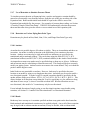
The coding on the NODE DATA screen is basically the same as that for the operating
case except that where spring hangers are desired, you should enter Y in the SPRING?
field of the Restraints Specification screen. The next field, Spring Var.(%), is for the
load variation in percentage.
Load~Variation~=~{installed load~-~operating load} over {operating~load}
(c)
Use of this field will instruct TRIFLEX to limit the load variation to no more than the
percentage specified (Default is 25%). [TRIFLEX will determine the operating load to
be carried by the spring hanger and the as-drawn-to-operating deflections for each.] If
two or more springs are desired at a location in a piping system, you may enter the
request for additional springs in the field No. of Springs:
Where the Spring Hanger attachment location is within four pipe diameters in a
horizontal plane from a rigid anchor or expansion joint, you may enter Y in the field
FREEHY for the anchor or zero-length expansion joint detail. This allows the spring
hanger, which is sufficiently close to a rigid anchor or expansion joint, to carry
essentially the entire vertical force rather than share the load with the anchor. If the pipe
is relatively far from the anchor, the entire load will not be carried by the spring since the
pipe between the anchor and the support location is flexible. Do not use FREEHY in
such instances.
In the sample problem below, FREEHY has been specified for data point 5. The restraint at data
point 20 (proposed spring hanger location) is within four pipe diameters of the anchor (data point
5). FREEHY has not been specified at data points 45 and 90 since the restraint at data point 100
was more than fur pipe diameters away from data point 105, and a valve is between data points
45 and 55. The internal analysis procedure utilized by TRIFLEX is the same as that outlined for
the manual method described in Section 5.2.
15
TRIFLEXWindows
5.3
Chapter 5
Spring Hanger Output Report
The output will consist of the following reports:
1)
Operating Case Analysis (Thermal + Pressure + Weight). All anchors and expansion
joints which had a FREEHY specified will be treated as rigid for this analysis.
2)
Spring Hanger Sizing Report. This will show the as-drawn-to-operating
deflection, the operating load for the springs at each specified data point, the
minimum required and mid-range spring hanger with the calculated installed load,
the spring rate, and the percent load variation.
A minimum required hanger is sized using the entire recommended working range of the spring
hanger as specified in the manufacturer's catalog.
A mid-range hanger is sized using the middle seventy-five (75%) percent of the recommended
working range of the spring hanger as specified in the manufacturer's catalog.
After the Spring Hanger Sizing report is generated, you may select the range criterion which
approximates company policy and specify springs accordingly.
5.4
Expansion Joints
Expansion joints may be modeled easily and accurately using TRIFLEX. Expansion joints are
like anchors in many respects. The major difference between them is that flexible anchors act as
springs between the pipe and the rigid external system, while expansion joints act as internal
springs between two sections of pipe and are both free to move with respect to the rigid external
system.
To model an expansion joint, an expansion joint data point type with a run of pipe should be
coded to the centroid of the expansion joint. The stiffnesses for the Expansion Joint Data Point
Type shall be specified in the fields EJT and EJR in the Expansion Joint Detail window.
Torsional flexibility is generally ignored because of its relative rigidity. Axial, lateral, and
angular spring rates are generally entered depending upon the particular Expansion Joint
configuration being modeled.
When entering the expansion joints, you should be aware of their effect on the piping system.
While adding significant flexibility to a piping system, an expansion joint may create a
significant pressure thrust problem. Pressure thrust is the effect of internal pressure forcing the
ends of the expansion joint apart axially. Pressure thrust is also the effect of external pressure
forcing the ends of the expansion joint together axially. When a pipe contains pressure, the
longitudinal fibers of the pipe restrain the pipe from excessive axial extension. When an
expansion joint contains pressure, the axial spring rate of the expansion joint, or some external
means such as tie-rods or piping anchors, resist the tendency of the expansion joint to expand
16
TRIFLEXWindows
Chapter 5
axially. In any piping system containing significant internal pressure or vacuum, you must
provide either tie-rods or external anchors sufficient in design to resist the pressure thrust.
Pressure thrust is calculated as follows:
Pressure~Thrust~=~(P)(A)
where
Pressure thrust, lbs.
P = Internal pressure (+) or vacuum (-), psig
A = Effective area of the Expansion Joint, in.2
Where tie-rods are specified and you do not want to model the tie-rods in a closed-loop fashion,
do not enter the axial spring rate or the AREA of the expansion joint. For the piping segments
inside the tie-rod connectors, the coefficient of expansion should be zero or the temperature
ambient. Where tie-rods are not specified, enter the expansion joint area utilizing the field
AREA=. See Section 4.2 Sample Coded Data Points for illustrations. You should be aware that
if the axial force tending to compress the expansion joint is greater than the pressure thrust in an
expansion joint having tie-rods, the tie-rods will not absorb the pressure thrust and the expansion
joint will compress by an amount determined by the axial flexibility and the axial force minus
the pressure thrust force.
Adequate guiding of the piping involved in an expansion joint installation is important to ensure
the efficient operation of the expansion joint.
The following is taken from Standards of the Expansion Joint Manufacturers Association, Inc.
In locating pipe alignment guides for applications involving axial movement only, it is generally
recommended that the Expansion Joint be located close to an Anchor and that the first pipe guide
be located a maximum distance of four pipe diameters from the end of the bellows. The distance
between the first pipe guide and the second must be a maximum of fourteen pipe diameters.
Intermediate alignment guides beyond the second guide are also recommended and should be
placed using the following equation taken from the above referenced standard.
Maximum intermediate guide spacing for any pipe material or thickness may be calculated using
the following formula:
L~=~0.131 sqrt{{EI} over {pa~ plusminus~ fe_x }}
where
L = Maximum intermediate guide space, (feet)
E = Modulus of elasticity of pipe material, (psi)
I = Moment of inertia of pipe, (in4)
p = Design pressure, (psig)
a = Bellows effective area, (in2)
17
TRIFLEXWindows
Chapter 5
f = Bellows initial spring rate per convolution, (lb/in/conv.)
e = Axial stroke of bellows per convolution, (in/conv.)
Note: When bellows is compressed in operation, use
+~ line~fe_x~ line
when extended, use
-~ line~fe_x~ line
TRIFLEX supplies you with all the information required to specify an expansion joint. After the
analysis, the deflections and rotations may be checked to verify that the expansion joint having
the properties which were used in the analysis will safely absorb the deflections and rotations.
18
TRIFLEXWindows
Chapter 5
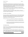
If the deflections at the ends of an expansion joint are in opposite directions, the total deflection
for the expansion joint is the sum of their absolute values. In other words, if the left side of an
expansion joint moves to the left and the right side moves to the right, the total movement
absorbed by the expansion joint would be the sum of both deflections ignoring the positive or
negative sign as shown below:
DATA POINT
DX
DY
DZ
RX
RY
RZ
45 RUN END
50 RUN END
50 EXPN JOINT
0.562 0.000 0.121 0.031 0.102 0.002
0.500 0.000 0.121 0.031 0.102 0.002
0.250 0.000 0.121 0.031 0.102 0.002
Total Movement = 3/4" Extension
If the deflections at the ends of an expansion joint are in the same direction, the total deflection
for the expansion joint is the difference in their absolute values. The two possibilities for this
type motion are shown below:
TOTAL MOVEMENT = 1/4" EXTENSION
TOTAL MOVEMENT = 1/4" COMPRESSION
The procedure for calculating total angular rotation for expansion joints is identical to the
procedure for deflections.
After determining the total translations and rotations of the expansion joint, be sure to check the
manufacturer's literature to see that the joint can safely absorb the total travel. If a bellows type
joint is being used, a larger number of convolutions will increase the total translation and rotation
which can be absorbed.
Occasionally, situations arise in piping systems where the ability to allow the pipe to move along
an axis a specified distance before a restraint is encountered is desirable. This ability is further
enhanced when the pipe can be moved initially a specified distance and then is free to move an
additional specified distance before a restraint with a known or unknown stiffness is
encountered. In TRIFLEX the limit stop fields may be utilized to accomplish this effect. These
fields are found on
Restraint Specifications screen. On this screen, TRIFLEX permits the user to specify the most
positive (upper) limit, the least positive (lower) limit, and the stiffness (spring constant) of the
limit stop. Limits stops may be skewed if desired.
Modeling Techniques
1)
Limit stop with positive and negative axis limit specified:
19
TRIFLEXWindows
Chapter 5
Conditions exist where you may want to allow the pipe to be free to move in both the positive
and negative directions before a restraint is encountered. The following screen input example
illustrates the input requirements for this type of limit stop usage:
This limit stop allows the pipe freedom to move 1.5 inches in both the positive
and negative Z-axis directions before a flexible restraint with a stiffness of
100,000 lbs/in is encountered. The specified limits allow the pipe to move freely
a total of 3.0 inches. (1.5 inches in the positive direction to 1.5 inches in the
negative direction).
2)
Limit stop with only one limit specified:
Conditions exist where you may wish to allow the pipe to be free to move in only
one axis direction for a specified distance before a restraint is encountered and not
allow the pipe to move in the other axis direction. The following example
illustrates the input requirements for this type of limit stop usage:
The above limit stop is free to move 2.25 inches in the negative X-axis direction before a rigid
restraint is encountered and is restrained in the positive X-axis direction from movement.
3)
Limit stop with positive initial movement specified:
You may wish to allow the pipe to move in the positive axis direction for a specified distance
before a rigid restraint is encountered, and also initially move the pipe in the same axis direction.
The following example illustrates the input requirements for this type of limit stop usage:
The above limit stop has an initial movement of 2.00 inches in the positive X-axis direction. The
pipe is then free to move another 3.5 inches in the positive X-axis direction before a rigid
restraint is encountered.
4)
Limit stop with negative initial movement specified:
You may wish to allow the pipe to move in the negative axis direction for a specified distance
before a rigid restraint is encountered, and also initially move the pipe in the same axis direction.
The following example illustrates the input requirements for this type of limit stop usage:
The above limit stop at data point 20 has an initial movement of -1.50 inches in the negative
X-axis direction. The pipe is then free to move another 1.5 inches in the negative X-axis
direction.
20