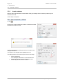
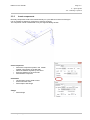
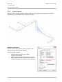
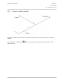
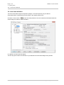
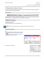
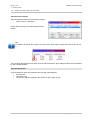
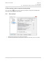
1
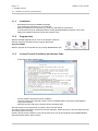
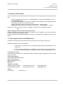
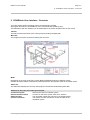
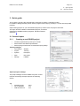
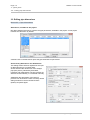
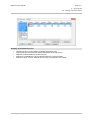
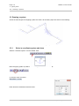
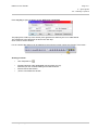
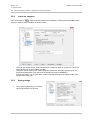
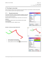
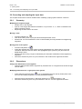
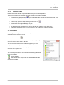
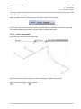
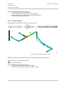
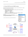
ROHR2 P r o g r a m S y s t e m f o r S t a t ic a n d D y n a m ic A n a l y s is o f C o m p le x P i p in g a n d S k e le t a l S t r u c t u r e s ROHR2 31.2a Tutorial ROHR2 Introduction - Editing a Piping System Release 31.2a January 2014 Release 150130 SIGMA Ingenieurgesellschaft mbH Contents of this document are subject to change without notice. The manual is protected by copyright. No part of this document may be reproduced or transmitted in any form or by any means, electronic or mechanical, for any purpose, without permission. Specifications subject to change without notice. All of the mentioned products and brand names are trademarks or indexed trademarks of the respective manufacturers. Software-Support, German Software-Support, English ++49 (0) 2303 332 33 33 ++49 (0) 2303 332 33 44 Published by SIGMA Ingenieurgesellschaft mbH Bertha-von-Suttner-Allee 19 D-59423 Unna Germany Telephone +49 (0)2303 332 33-0 Telefax +49 (0)2303 332 33-50 E-mail: [email protected] Internet: www.rohr2.de www.rohr2.com [email protected] [email protected] ROHR2 31.2a Tutorial Page i Contents Contents 1 ROHR2 Tutorial .........................................................................................................................................1-1 1.1 1.1.1 1.1.2 1.1.3 1.1.4 1.1.5 ROHR2 test license (full featured) ..............................................................................................................1-1 Required data .............................................................................................................................................1-1 Settings .......................................................................................................................................................1-1 Installation...................................................................................................................................................1-2 Program start ..............................................................................................................................................1-2 License Terms & Conditions and Access Code ..........................................................................................1-2 1.2 Projects and Examples ...............................................................................................................................1-3 1.3 User support, hotline and ROHR2 board ....................................................................................................1-3 2 ROHR2win User Interface - Overview .....................................................................................................2-1 3 Quick guide ...............................................................................................................................................3-1 3.1 3.1.1 General inputs ............................................................................................................................................3-1 Creating a new ROHR2 project ..................................................................................................................3-1 3.2 Editing pipe dimensions ..............................................................................................................................3-2 3.3 3.3.1 3.3.2 3.3.3 3.3.4 3.3.5 Drawing a system .......................................................................................................................................3-4 Select a coordinate system and draw .........................................................................................................3-4 Insert a reducer...........................................................................................................................................3-6 Insert components ......................................................................................................................................3-7 Insert supports ............................................................................................................................................3-8 Support condition symbols ..........................................................................................................................3-9 3.4 Load case definition ..................................................................................................................................3-10 3.5 Assign operation data per load case .........................................................................................................3-11 3.6 3.6.1 3.6.2 3.6.3 Stress analysis, loads on supports and spring design ..............................................................................3-13 Stress analysis..........................................................................................................................................3-13 Loads on supports ....................................................................................................................................3-14 Spring design ............................................................................................................................................3-14 3.7 3.7.1 Checking the input data ............................................................................................................................3-15 Segment parameters ................................................................................................................................3-15 3.8 3.8.1 3.8.2 3.8.3 Correcting and adapting the input data .....................................................................................................3-16 Geometry ..................................................................................................................................................3-16 Dimensions ...............................................................................................................................................3-16 Operation data ..........................................................................................................................................3-17 3.9 Calculation ................................................................................................................................................3-17 3.10 Results analysis ........................................................................................................................................3-19 3.10.1 Load case results ......................................................................................................................................3-19 3.10.2 Stress analysis..........................................................................................................................................3-20 4 Checking CAD/CAE import with ROHR2 Interfaces ...............................................................................4-1 SIGMA Ingenieurgesellschaft mbH www.rohr2.com Page ii ROHR2 31.2a Tutorial Contents www.rohr2.com SIGMA Ingenieurgesellschaft mbH ROHR2 31.2a Tutorial Page 1-1 1 - ROHR2 Tutorial 1.1 - ROHR2 test license (full featured) 1 ROHR2 Tutorial Thank you for reading this document, introducing into the work with the program system ROHR2. This manual is applicable to the ROHR2 full license ROHR2 test license We would be very pleased to provide you with a program license or viewer download. Please contact our sales department in Germany ([email protected]) or one of the ROHR2 sales partners (see www.rohr2.com for contact details). 1.1 ROHR2 test license (full featured) The test license is identical to the full license including optional available modules and interfaces. The test license includes the entire capability of the ROHR2 standard package and it´s modules and interfaces. The test license includes optional modules and interfaces whch may be different from the your inquiry/order and the quoted/delivered program. The test program is provided by download and can be used under conditions of non-commercial use. Running a test license requires a contact to the SIGMA test license server by internet connection. The technical requirements are specified in an installation document. Please contact us by email ([email protected]), use the contact form on www.rohr2.com or call us. A test license is provided - by sending a program package including license key (USB-plug) or - by an access to the ROHR2 test license server. The following instruction shows how to get a test license with access to the ROHR2/SINETZ license server. 1.1.1 Required data We would be very pleased to provide you with a full featured test license. Please contact our sales department in Germany ([email protected]) or one of the ROHR2 sales partners (see www.rohr2.com for contact details). You will receive - a download link - a license access code 1.1.2 Settings The following settings are required for the access to the license server: make sure that port 1947 (UDP + TCP) is not blocked for the access to the test server (possibly it is blocked by the Windows firewall!) SIGMA Ingenieurgesellschaft mbH www.rohr2.com Page 1-2 ROHR2 31.2a Tutorial 1 - ROHR2 Tutorial 1.1 - ROHR2 test license (full featured) 1.1.3 - 1.1.4 Installation Download and unzip the installation package. Copy all files into a directory on your hard disk. Start the installation in this directory by setup.exe and follow the instructions The test license may be installed parallel to existing ROHR2/SINETZ programs. In this case please use a different directory name and program group Program start Start the ROHR2 application by a clock on the program symbol or start the programs manually from the program directories: Program ROHR2 Start the program in the test directory by running \R2WIN\R2win.exe. 1.1.5 License Terms & Conditions and Access Code - At first start a dialog window opens: - You are asked to accept the license conditions. The user agrees to the General Contract Terms of SIGMA GmbH, being basis of participation (copy upon request). Enter the access code which has been sent by the Sales team. The test license now is prepared to run until the end of the test period. The status of the test license is checked by internet frequently. Please be sure to have an internet access when the program is running. Please note: the scope of delivery of the server test license may be not identical to the ROHR2/SINETZ standard release and the demo version! www.rohr2.com SIGMA Ingenieurgesellschaft mbH ROHR2 31.2a Tutorial Page 1-3 1 - ROHR2 Tutorial 1.2 - Projects and Examples 1.2 Projects and Examples For an introduction into pipe stress analysis with ROHR2 we are providing projects and examples to the user. sample calculations are stored in the. ../ROHR2/R2BSP/... directory after installation of a fullfeatured ROHR2 license project files, explanations and movies of the ROHR2 tutorial examples can be downloaded from the website www.rohr2.com in the Service area. They can also be accessed by the program function HELP > Training videos. ROHR2 test license: sample calculations are stored in the. ../ROHR2/R2BSP/... directory Please refer to topic 3 of this document for a detailed introduction into a calculation example. Project editing by means of a full-featured test license Projects, created by the test license program are marked by TEST LICENSE. They can be opened and modified by a commercial program license. Projects, created by a full featured ROHR2 license only can be opened and modified by means of a test license. 1.3 User support, hotline and ROHR2 board All software commands are documented in the user manual and in the program online help. Additional information sources are available in the internet, e.g. ROHR2 Forum incl. ROHR2 FAQ (Frequently asked questions), see Help menu, the user support providing advice on installation and application of the program (hotlineservice) on workdays (Mondays to Fridays) from 9.00 - 16.00 (Central European Time). User support by email An email function, integrated in to ROHR2win enables to transmit program data directly (see menu Help |Support request). User support address SIGMA Ingenieurgesellschaft mbH Dept. Program-Support Bertha-von-Suttner-Allee 19 D-59423 Unna Germany Telephone and email Software-Support, German Software-Support, English Internet www.rohr2.de ++49 (0) 2303 332 33 33 ++49 (0) 2303 332 33 44 [email protected] [email protected] www.rohr2.com SIGMA Ingenieurgesellschaft mbH www.rohr2.com Page 1-4 ROHR2 31.2a Tutorial 1 - ROHR2 Tutorial 1.3 - User support, hotline and ROHR2 board www.rohr2.com SIGMA Ingenieurgesellschaft mbH ROHR2 31.2a Tutorial Page 2-1 2 - ROHR2win User Interface - Overview 2 ROHR2win User Interface - Overview The input window shows the piping system and the drawing created. All program functions are accessible by menu commands and symbols (icons). The elements of the user interface can be positioned on the screen be placed free on the screen. Title bar The title bar shows the name of the current project including complete path. Menu bar The program functions can be accessed by the menu bar. Mode Depending on the view mode (see Toolbar Mode) ROHR2win appears in different modes. Activate the mode related commands by switching between the program states in the toolbar mode. Status bar The status bar displays the currently used program command and selected system data. Elements in the lower part of the input window Coordinate system General Overall window Output window Current calculation Showing the Global coordinate system overview on the entire system with zoom function The calculation output text is shown in the output window The window Current calculations shows the tasks in the calculation queue SIGMA Ingenieurgesellschaft mbH www.rohr2.com Page 2-2 ROHR2 31.2a Tutorial 2 - ROHR2win User Interface - Overview www.rohr2.com SIGMA Ingenieurgesellschaft mbH ROHR2 31.2a Tutorial Page 3-1 3 - Quick guide 3.1 - General inputs 3 Quick guide This chapter is showing the essential steps necessary to define a calculation model. For details to dialog windows please use the program online-help by pressing F1 or look into the printed manuals. Open training projects or your own ROHR2 projects by means of the File| Open command. The Open function enables to load ROHR2 projects, as well as CAD data by ROHR2 interface programs. See also ROHR2 interfaces 4. 3.1 General inputs 3.1.1 Creating a new ROHR2 project Create a project directory with up to 3 levels Select stress code /Stress specification Select spring manufacturer for automatics spring design Training settings1 Commission: Project: System: Spec. .: Springs: SIGMA Training Example1 EN 13480 LISEGA Options| Project settings The project settings can be modified every time. At this moment the training example requires the following entries: e.g. Assembly temp. unit coordinates Wall thickness tol. 20°C mm mm SIGMA Ingenieurgesellschaft mbH www.rohr2.com Page 3-2 ROHR2 31.2a Tutorial 3 - Quick guide 3.2 - Editing pipe dimensions 3.2 Editing pipe dimensions Menu edit > Pipe dimensions Dimensions, available in the project Die dialog window Dimensions contains the pipe parameters, available in the project. A new project includes one dimension by default. A double-click on the dimension opens the pipe dimensions input window. All necessary dimensions are defined here This dialog window offers 6 registers for the input of data belonging to a nominal width. At first there are the dimensions of the straight pipe (see picture), followed by bend data, insulation and material data. The line masses are determined automatically, if not entered manually. Additionally the parameters of the internal pressure can be inserted. There are nearly similar dialog windows for structural steel sections (beams) and jacket pipes. www.rohr2.com SIGMA Ingenieurgesellschaft mbH ROHR2 31.2a Tutorial Page 3-3 3 - Quick guide 3.2 - Editing pipe dimensions Handling of the Dimensions list Use filter functions for the display of desired parameters only: press STRG-key and select the desired parameters in the left column. Adaption by table header for several columns. Selection by materials file: sort by name/number in the column header. If listed by name: use the character keys to jump to the position in the table. SIGMA Ingenieurgesellschaft mbH www.rohr2.com Page 3-4 ROHR2 31.2a Tutorial 3 - Quick guide 3.3 - Drawing a system 3.3 Drawing a system At first the main lengths of the piping system are drawn. All necessary steps are shown in the following. figure: system lines 3.3.1 Select a coordinate system and draw Select a coordinate system from the toolbar View Draw the piping system by means of the drawing tool from the toolbar Edit or user the menu command Menu Edit > Draw Enter absolute coordinates of the first node www.rohr2.com SIGMA Ingenieurgesellschaft mbH ROHR2 31.2a Tutorial Page 3-5 3 - Quick guide 3.3 - Drawing a system Press any key to open the dialog window difference coordinates The piping from C1/N1 up to the anchor point right below is drawn by the nom. width DN150. The assignment o the dimension is done in the next step. Click Close to exit the window. For an overview the drawing can be adapted to the maximum screen size by the function Zoom limits. . Oder menu right mouse button Drawing a branch Use Edit| Draw or Get the branching node (highlighted red) and press any key. After that you can continue drawing as mentioned above. Draw a branch with DN150 „Close“ to terminate the window SIGMA Ingenieurgesellschaft mbH www.rohr2.com Page 3-6 ROHR2 31.2a Tutorial 3 - Quick guide 3.3 - Drawing a system 3.3.2 Insert a reducer When a reducer is inserted the nominal width of the pipe changes from the reducer position up to a selected end node. These steps are required. Edit > Insert component > Reducer or use . Click into the segment where the reducer is inserted and enter the distance to the next node. Confirm this message by OK and enter the end node of the changed dimension. The region to be changed will be highlighted in red. The dialog window Insert reducer opens for the next steps: Select a dimension if not existing the dimension can be inserted here. Select reducer from the norm DIN 2616, part 2 Confirm by OK and insert the reducer. www.rohr2.com SIGMA Ingenieurgesellschaft mbH ROHR2 31.2a Tutorial Page 3-7 3 - Quick guide 3.3 - Drawing a system 3.3.3 Insert components Normally components need to be inserted directly on a pre-defined center line of the pipe. It is not possible to append a component to a drawn segment. The component can be modified later on by the segment dialog window. Insert component Select the component symbol in the toolbar (toolbar components on the left side) select the desired segment by the cursor Enter the distance to the next node Select/define component Instrument: Length seal to seal or weld to weld Enter instrument mass Select Option with flange Flange: Select flange SIGMA Ingenieurgesellschaft mbH www.rohr2.com Page 3-8 ROHR2 31.2a Tutorial 3 - Quick guide 3.3 - Drawing a system 3.3.4 Insert supports Supports may be inserted at existing nodes or segments. If the user places a support into a segment, automatically an intermediate node is created at this place. Defining a rigid support ROHR2 regards sliding supports, bearing supports, axial stops and anchor points as rigid supports. The way to insert a support: select the type of support in the toolbar (toolbar on the left side) select the desired node or segment by the cursor define support. Alternatively here types of support or components (degrees of freedom) may be assigned. www.rohr2.com SIGMA Ingenieurgesellschaft mbH ROHR2 31.2a Tutorial Page 3-9 3 - Quick guide 3.3 - Drawing a system 3.3.5 Support condition symbols All supports of this example at first are calculated considering the standard values of friction, gap and stiffness. The design of the spring hanger inputs required). SIGMA Ingenieurgesellschaft mbH shall be carried out by the program (Default-settings, no more www.rohr2.com Page 3-10 ROHR2 31.2a Tutorial 3 - Quick guide 3.4 - Load case definition 3.4 Load case definition The load cases Dead weight and operation (Weight + thermal expansion) are pre-defined. View global loads, considered by the load cases in the register global loads. Use Menu Loads| Tasks or to open the dialog window Load case definition and ROHR2 tasks like stress analysis or extreme value calculation For definition of load cases see below. The first step just includes the calculation of pre-defined load cases dead weight and operation. www.rohr2.com SIGMA Ingenieurgesellschaft mbH ROHR2 31.2a Tutorial Page 3-11 3 - Quick guide 3.5 - Assign operation data per load case 3.5 Assign operation data per load case It is important to define operation data per load case for the calculation. Before assigning the operation data at first the load case must be specified. Select load case Operation data are assigned by segments. At first highlight the segments where identical operation data will be assigned to. The operation data must be assigned to all segments. Highlight parts of the system To select the entire system use Menu Edit| Select| All, All selected parts of the system are highlighted red. Tip The Select command can be found in the Context menu (right mouse button), too). Select parts of the system Use Loads| Operation data| Referring to load cases or a dialog window opens where record types with operation data can be defined. Define a new record by Add. SIGMA Ingenieurgesellschaft mbH www.rohr2.com Page 3-12 ROHR2 31.2a Tutorial 3 - Quick guide 3.5 - Assign operation data per load case Operation data example Identical Operation data in the whole piping system: 20 bar / 285°C / 1000 kg/m³ Assign data by Assign to the selected parts of the system. Tip If the data is assigned, the symbol in the first column of the table changes from blue circle to a red X. The operating data dialog window stays open for further treatment. Open dialog windows can be identified by their colored headline Copy operation data Copy the data from load case Operation into the load case Weight by Select record Command Copy Choose the load case Weight in the select box and confirm by OK. www.rohr2.com SIGMA Ingenieurgesellschaft mbH ROHR2 31.2a Tutorial Page 3-13 3 - Quick guide 3.6 - Stress analysis, loads on supports and spring design 3.6 Stress analysis, loads on supports and spring design Use Loads| Tasks or to open the dialog window for the definition of load cases and ROHR2-tasks. At first select a stress analysis in the left column. 3.6.1 Stress analysis Define the stress code here to be used for the calculation. The load case superposition for this load case is carried out automatically, but can be modified. SIGMA Ingenieurgesellschaft mbH www.rohr2.com Page 3-14 ROHR2 31.2a Tutorial 3 - Quick guide 3.6 - Stress analysis, loads on supports and spring design 3.6.2 Loads on supports Use Loads| Tasks or to open the dialog window for the definition of load cases and ROHR2-tasks. Select an extreme value calculation in the left column. 3.6.3 The load case superposition, used to determine the maximum loads on supports is carried out automatically, but can be modified manually. The option „Show results of the created load case graphically“ offers the opportunity for the graphical representation of the results of combined load cases in ROHR2win. Activate this option, e.g. for generation of loads overviews basing on the support loads of the extreme value load case. Spring design Carry out the spring design for various spring manufacturers at any time www.rohr2.com SIGMA Ingenieurgesellschaft mbH ROHR2 31.2a Tutorial Page 3-15 3 - Quick guide 3.7 - Checking the input data 3.7 Checking the input data After finishing the piping model and defining the first load cases it may be useful to check the input data. This can be done by the function Segment parameters. 3.7.1 Segment parameters The function Properties | Segment parameters enables to check the input data by selecting segments by means of specified properties. Choose the desired parameter. Several entries can be entered at the same time in the select box. Selection The segments containing the chosen parameters are selected Colored display The properties are shown in different colors Example, checking assigned dimensions Select parameter Nominal width Use the option Color presentation Show system as volume model SIGMA Ingenieurgesellschaft mbH Symbol Dimensions www.rohr2.com Page 3-16 ROHR2 31.2a Tutorial 3 - Quick guide 3.8 - Correcting and adapting the input data 3.8 Correcting and adapting the input data This chapter shows some common mistakes when modeling a piping system and their correction. 3.8.1 Geometry Modifying the segment length Double-click on the segment Input of a new length with identical orientation or input of the X-, Y-, and Z-coordinate in the global coordinate system Displacing the start node or end node Moving a node Function Edit| Move or Click at the node, press any key and enter the displacement vector Please note: it is recommended to move an intermediate point only between two neighboring segments. Moving parts of the system 3.8.2 Function Edit| Select or At first the required part of the system must be highlighted by the Select Start to end node command. After that click at a node in the highlighted region, press any key and enter the displacement vector. Please note that moving a region is followed by the automatic modification of the neighboring segments. Cancel the selection by ESC or by End function in the context menu /right mouse button Dimensions Change the dimensions of one segment Open the dialog window Data of segments by a double-click on a segment and choose the right nominal width. Modifying dimensions for a region/part of the system At first select the desired region . E.g. by highlighting the main part by Select| Start node… end node and adding segments by Select| Individual elements. After that choose a dimension by Edit| Pipe dimensions or and assign by OK. Cancel the selection by ESC or by End function in the context menu /right mouse button. www.rohr2.com SIGMA Ingenieurgesellschaft mbH ROHR2 31.2a Tutorial Page 3-17 3 - Quick guide 3.9 - Calculation 3.8.3 Operation data Please note that the definition of operation data is always load case dependent That’s why it is required to select the load case at first and then change the data. Then select the desired region . E.g. by highlighting the main part by Select| Start node… end node and adding segments by Select| Individual elements. Use Loads|-Operation data| Referring to load cases or Choose operation data or generate a new record Assign data to the highlighted region by OK. If desired the new generated record can be selected and copied into other load cases Cancel the selection by ESC or by End function in the context menu /right mouse button. 3.9 Calculation In the program directory there are some examples enabling to check the results and the documentation of ROHR2 analysis as shown below. Function File| calculate or All tasks, shown in the window can be calculated single or, by using the option All, the analysis is done for all tasks. The internal pressure check entry offers the opportunity to check components for internal pressure. Another check is the collision test, analyzing if there is a conflict between segments of the piping model. The colored symbols beneath the load cases are showing if the results have been updated. results updated the task has been changed after the last calculation and the results are not updated. SIGMA Ingenieurgesellschaft mbH www.rohr2.com Page 3-18 ROHR2 31.2a Tutorial 3 - Quick guide 3.9 - Calculation After finishing the calculation the results are summarized in an output window. green blue Everything is alright. The calculation runs without any mistakes General system information red Error messages. a problem occurs: The calculation result is totally missing or it is not recommended to use the result (e.g. the calculation did not use the required analysis accuracy) Warnings, Check the results! yellow Select one of the messages in the window to reach a help text. www.rohr2.com SIGMA Ingenieurgesellschaft mbH ROHR2 31.2a Tutorial Page 3-19 3 - Quick guide 3.10 - Results analysis 3.10 Results analysis Switch to Results mode in the Mode toolbar to show the results of the calculation. Here the load case results as well as the stress analyses with stress utilization can be shown graphically. In the following different opportunities of results analysis in ROHR2 are shown: 3.10.1 Load case results At first select the load case in the results mode Fig.: deformed structure Get single results by double-clicking at a node and selecting the register Single results To get an overview in tables, use the symbols / Cross section results or SIGMA Ingenieurgesellschaft mbH / Loads on supports. www.rohr2.com Page 3-20 ROHR2 31.2a Tutorial 3 - Quick guide 3.10 - Results analysis By this way different results can be shown, e.g.: max. bending in the load case Weight Loads on supports at nozzle C1 in the load case Weight vertical expansion at the spring support in load case operation the spring type selected by ROHR2 3.10.2 Stress analysis At first select the required stress analysis in the results mode. Ausn. [%] >100 100 11 95 90 85 20 80 75 10 70 65 60 19 55 50 18 45 40 35 30 25 5 20 15 3 10 5 0 12 9 1 678 4 2 13 14 15 16 17 Ya Za Xa Figure: Stress analysis equation 4 (weight + range) Get single results by double-clicking at a node and selecting the register Stress analysis To get an overview in tables, use the symbol / cross sectional results. By this way different results can be shown, e.g.: maximum stress utilization of analysis 1 (weight) maximum stress utilization of analysis 1 (weight + range) www.rohr2.com SIGMA Ingenieurgesellschaft mbH ROHR2 31.2a Tutorial Page 4-1 4 - Checking CAD/CAE import with ROHR2 Interfaces 4 Checking CAD/CAE import with ROHR2 Interfaces The program system ROHR2 offers a wider angle of interfaces to CAD and CAE systems. For details please refer to the ROHR2 Interface feature list. The ROHR2 standard program delivery includes: Neutral CAD Interface, enables import from CAD/CAE systems like PDMS, CADISON, RC-Planet, HICADnext, and others Export AVEVA PDMS - ROHR2, CAESAR II Import Interface PIPESTRESS Import Interface SINETZ Export interface Export Interface into the Support Design Programs LICAD, FLEXPERTE, CASCADE (For additional details please refer to the ROHR2 program description) All import formats are available in the demo program *). Load the data by means of File| Open command and get an overview on the capacity of the import interfaces. *) some of the interface modules are optionally available products. www.rohr2.com SIGMA Ingenieurgesellschaft mbH Page 4-2 ROHR2 31.2a Tutorial 4 - Checking CAD/CAE import with ROHR2 Interfaces www.rohr2.com SIGMA Ingenieurgesellschaft mbH


![[PSS 21S-2B11 B4] Field Device Manager for IACC and](http://vs1.manualzilla.com/store/data/005879688_1-2c218fc20ab8a2ac5340bc4e42ae00e6-150x150.png)