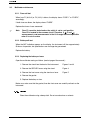
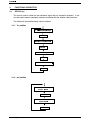
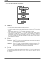
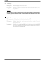
1
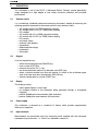
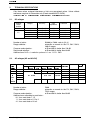
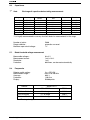
PORTABLE DIGITAL MULTIMETER
MODEL MX53III
USER MANUAL
®
INSTRUMENTS
&KDSWHU ,
USER'S MANUAL CONTENTS
1. GENERAL INSTRUCTIONS.................................................................................................................. 1
1.1. Precautions and safety measures........................................................................................................... 1
1.1.1. Before use........................................................................................................................................ 1
1.1.2. During use........................................................................................................................................ 1
1.1.3. Symbols............................................................................................................................................ 2
1.1.4. Opening the instrument.................................................................................................................... 2
1.2. Protection devices ................................................................................................................................... 2
1.3. Safety devices ......................................................................................................................................... 3
1.4. Warranty.................................................................................................................................................. 3
1.5. Maintenance and metrological verification .............................................................................................. 3
1.6. Unpacking - Repacking ........................................................................................................................... 3
2. DESCRIPTION ....................................................................................................................................... 4
2.1. Selector switch ........................................................................................................................................ 4
2.2. Keypad .................................................................................................................................................... 4
2.3. Display..................................................................................................................................................... 4
2.4. Power supply........................................................................................................................................... 4
2.5. Input terminals......................................................................................................................................... 4
3. COMMISSIONING ................................................................................................................................. 5
3.1. Connecting the test leads........................................................................................................................ 5
3.2. Switching on the instrument .................................................................................................................... 5
3.3. Switching off the instrument .................................................................................................................... 5
3.4. Special configurations ............................................................................................................................. 5
3.5. Multimeter maintenance.......................................................................................................................... 6
3.5.1. Fuse self-test.................................................................................................................................... 6
3.5.2. Battery self-test ................................................................................................................................ 6
3.5.3. Replacing the battery or fuses ......................................................................................................... 6
3.5.4. Cleaning ........................................................................................................................................... 6
4. FUNCTIONAL DESCRIPTION .............................................................................................................. 7
4.1. SEL/ON key............................................................................................................................................ 7
4.1.1. VAC position ...................................................................................................................................... 7
4.1.2. mV position ...................................................................................................................................... 7
4.1.3. VDC position ...................................................................................................................................... 8
4.1.4. Ω position ......................................................................................................................................... 8
position........................................................................................................................................ 8
4.1.5.
4.1.6. 5 mA / 50 mA / 500 mA / 10 A positions .......................................................................................... 9
4.2. RANGE key............................................................................................................................................. 9
4.3. REL key................................................................................................................................................... 9
4.4. Pk +/- key ................................................................................................................................................ 9
4.5. HOLD key.............................................................................................................................................. 10
4.6. PRINT key............................................................................................................................................. 10
5. TECHNICAL SPECIFICATIONS ......................................................................................................... 11
5.1. DC voltages........................................................................................................................................... 11
5.2. AC voltages (AC and AC+DC) .............................................................................................................. 11
5.3. DC current............................................................................................................................................. 12
5.4. AC currents (AC and AC+DC) .............................................................................................................. 12
5.5. Resistance / Continuity.......................................................................................................................... 12
5.6. Capacitance .......................................................................................................................................... 13
5.7. Diode threshold voltage measurement ................................................................................................. 13
5.8. Frequencies .......................................................................................................................................... 13
5.9. Duty cycle %+, %- ................................................................................................................................. 14
6. GENERAL SPECIFICATIONS............................................................................................................. 15
6.1. Accessories ................................................................................................................................... 16
3RUWDEOH GLJLWDO PXOWLPHWHU
&KDSWHU ,
*(1(5$/ ,16758&7,216
You have just acquired a portable digital multimeter and we thank you for your purchase.
This instrument complies with the specification of IEC publication 1010-1, concerning safety
requirements for electronic measuring apparatus. To get the best service from this
instrument, read carefully this user's manual and respect the detailed safety precautions.
3UHFDXWLRQV DQG VDIHW\ PHDVXUHV
%HIRUH XVH
can be used for measurements on category ΙΙΙ installations, pollution
rating 2, for voltages never exceeding 600 V (AC or DC) relative to the earth.
7KLV GHYLFH
'HILQLWLRQ RI RYHUYROWDJH FDWHJRULHV FI SXEOLFDWLRQ ,(& CAT I :
The circuits of CAT I are protected by measures limiting transient
overvoltages to appropriate low level.
Example : protected electronic circuits
CAT II :
The circuits of CAT II are power supply circuits of appliances or portable
equipment with transient overvoltages of an average level.
Example : appliances and portable equipment
CAT III : The circuits of CAT III are power supply circuits of power equipment with
important transient overvoltages.
Example : fixed installation or industrial equipment
CAT IV : The circuits of CAT IV may comprise very important transient
overvoltages.
Example : primary supply level
∗ For your own safety, only use the measuring probes which have been delivered with
the instrument : they conform to the IEC 1010-1 safety standard. Before use, check
that they are in good condition.
'XULQJ XVH
∗ Test equipment risk assessment : Users of this equipment and or their employers
are reminded that Health and Safety Legislation require them to carry out a valid
risk assessment of all electrical work so as to identify potential sources of
electrical danger and risk of electrical injury such as from inadvertent short
circuits. Where the assessment show that the risk is significant then the use of
fused test leads constructed in accordance with the HSE guidance note GS38
"Electrical Test Equipment for use by Electricians" should be used.
∗ Never exceed the protection limit values indicated in the specifications for each
type of measurement.
∗ When the multimeter is connected to energized circuits, do not touch unused
terminals.
Portable digital multimeter
&KDSWHU ,
∗ When the scale of the value to be measured is unknown, check that the scale
initially set on the multimeter is the highest possible or, wherever possible, choose
the autoranging mode.
∗ Before changing functions, disconnect the test leads from the circuit under test.
∗ When performing current measurements, do not connect or disconnect leads
without first isolating the current. If you do, there is a risk of generating surge
currents which can blow the fuses or damage the instrument.
∗ In TV repair work, or when carrying out measurements on power switching circuits,
remember that high amplitude voltage pulses at the test points can damage the
multimeter. Use of a TV filter will attenuate any such pulses.
∗ Never perform resistance measurements on live circuits.
6\PEROV
W arning : Refer to the user's m anual.
Da ng e r, h ig h v oltage : R isk of elec tric sh oc k
E arth term ina l
2SHQLQJ WKH LQVWUXPHQW
∗ Before opening the instrument, always disconnect from all sources of electric
current and make sure not to be loaded with static electricity, which may destroy
internal components.
∗ Fuses must be replaced with fuses of the same rating and type.
∗ Any adjustment, maintenance or repair work carried out on the multimeter while it
is live should be carried out only by appropriately qualified personnel, after
having taken into account the instructions in this present manual.
A "qualified person" is one who is familiar with the installation, construction and
operation of the equipment and the hazards involved. He is trained and
authorized to energize, de-energize circuits and equipment in accordance with
established practices.
∗ When the instrument is open, remember that some internal capacitors can retain
a dangerous potential even after the instrument is powered down.
∗ It is recommended to remove the battery from the instrument if not used.
1.2.
Protection devices
ASYC II series instruments are fitted with various protection devices :
∗ Varistor protection for limiting transients of over 1100 V at the VΩ terminal,
particularly 6 kV pulse streams as defined in French standard NFC 41-102.
3RUWDEOH GLJLWDO PXOWLPHWHU
&KDSWHU ,
∗ A PTC (Positive Temperature Coefficient) resistor protects against permanent
overvoltages of up to 600 V during resistance, capacitance and diode test
measurements. This protection is reset automatically after overload.
∗ Two fuses provide protection during measurements of intensity type.
∗ Maximum protection between mA and 10 A input terminals : 500 V.
∗ An IP protection rating of 67.
1.3.
Safety devices
∗ The battery unit and fuses cannot be accessed without first disconnecting the
measuring leads.
∗ When measuring voltages above 24 V, the sign blinks
on the display.
∗ If the maximum range is repeatedly exceeded, an intermittent audible signal indicates
the risk of electric shock.
:DUUDQW\
This equipment is warranted against any defects of manufacture or materials according to
the general conditions of sale.
During the warranty period (3 years), defective parts will be replaced, the manufacturer
reserving the right to repair or replace the product. In the event of the equipment being
returned to the after sale department or to a local agency, carriage to the centre shall be
payable by the customer.
0DLQWHQDQFH DQG PHWURORJLFDO YHULILFDWLRQ
Return your instrument to your distributor for any work to be done within or outside the
guarantee.
8QSDFNLQJ 5HSDFNLQJ
This equipment has been fully checked out mechanically and electrically before shipping.
All precautions have been taken to ensure that the instrument arrives at its destination
undamaged.
However, it is advisable to carry out a rapid check for damage sustained in shipping.
If there is any evidence of damage, make this known immediately to the shipper.
*
)
Caution
Note
Should you need to return the multimeter, preferably use the original
packaging and indicate the reasons as clearly as possible on an
accompanying note.
Our products are patented in FRANCE and ABROAD. The logotypes
are registered.
The manufacturer reserves the right to modify specifications and prices
as required by technological improvements.
Portable digital multimeter
&KDSWHU ,
2.
DESCRIPTION
This multimeter is one of the ASYC II (Advanced SafetY Concept, second generation)
range, designed for a high degree of user safety, maximum protection and unrivalled
performance.
2.1.
Selector switch
It is a standalone, handheld professional measuring instrument, capable of measuring the
following quantities (accessed by the eleven-position rotary selector switch) :
∗
∗
∗
∗
∗
∗
∗
∗
∗
∗
∗
∗
2.2.
AC voltages with AC (or RMS) capacitive coupling,
AC voltages with AC+DC (or TRMS) direct coupling,
DC voltages,
AC currents with AC (or RMS) capacitive coupling
AC currents with AC+DC (or TRMS) direct coupling,
DC currents,
resistance values,
continuity (with beeper),
capacitance,
diode threshold voltage,
frequencies,
duty cycles
Keypad
A six-key keypad lets you :
∗
∗
∗
∗
∗
select the autoranging mode (RANGE key),
store a value (HOLD key),
measure fast peaks (Pk +/- key),
set the measurement relative to a reference value (REL key),
select a function derived from the main function, or switch on the multimeter again
after it has been shut down automatically (SEL/ON key),
∗ activate sending data to a printer (PRINT key).
2.3.
Display
The display provides :
∗ clearly legible figures (14 mm high),
∗ an analogue readout of the parameter being measured through a 34-segment
bargraph,
∗ perform 50 000-point measurements (high resolution),
∗ perform 5 000-point measurements (low resolution).
2.4.
Power supply
This multimeter is powered by a standard 9 V battery which provides approximately
500 hours of operation.
2.5.
Input terminals
Measurements are performed using two measuring leads supplied with the instrument
connected to input terminals 1, 2, 3 and 4, as indicated in section 3.1.
3RUWDEOH GLJLWDO PXOWLPHWHU
&KDSWHU ,
3.
COMMISSIONING
3.1.
Connecting the test leads
Connect the black lead to the COM socket (for all measurements). Depending on the
position of the selector switch, connect the red lead as follows:
Rotary selector switch position
3.2.
Input terminal
VAC, mVDC, VDC, Ω,
VΩ
10 ADC
A
5 mADC, 50 mADC, 500 mADC
mA
Switching on the instrument
Turn the selector switch to the required function.
All segments of the display come on for a few seconds. The instrument is then ready for
measurements.
3.3.
Switching off the instrument
The instrument can be switched off manually by returning the selector switch to the OFF
position, or automatically after approximately half an hour if no key is pressed or the switch
is not operated.
)
Note
Automatic shutdown of the instrument is disabled in order to avoid
interrupting the peak value measurements (Pk +/-), or the data print out.
For user safety, automatic shutdown is also disabled when a measured
magnitude (voltage/current) present at the input exceeds dangerous level
(
3.4.
indicator displayed).
Special configurations
To adapt the configuration of the instrument to the measurement environment, the user
can :
- Choose 50 Hz or 60 Hz rejection :
Switch on with the rotary switch while holding down the HOLD key. The selection is
reversed from the last configuration, is displayed for two seconds and remains
backed up in non-volatile memory.
- Choose a low resolution mode (5 000 points) :
Switch on with the rotary switch while holding down the REL key. The selection is
displayed for two seconds.
Portable digital multimeter
&KDSWHU ,
3.5.
Multimeter maintenance
3.5.1. Fuse self-test
When fuse F1 (0.63 A) or F2 (10 A) is blown, the display shows “FUSE.1” or “FUSE.2”,
accordingly.
If both fuses are blown, the display shows “FUSES”.
Replace the fuse or fuses concerned.
)
Note
Fuse F1 cannot be tested unless the switch is set to a mA position.
Fuse F2 is located in the common circuit. Therefore, V, Ω, C and
measurements, and measurements in the 10 A range, become impossible
when it is out of service.
3.5.2. Battery self-test
When the BAT indication appears on the display, the instrument still has approximately
50 hours of operation, but specifications can no longer be guaranteed.
Replace the battery.
3.5.3. Replacing the battery or fuses
Open the multimeter casing as follows (see last page of the manual) :
1 - Remove the stand from the back of the instrument.
Figures 2 and 3
2 - Remove the SECUR’X cover using the stand.
Figure 4
3 - Remove the front cover using the stand as a lever.
Figure 5
4 - Remove the gasket.
5 - Replace the battery or fuse.
Before use, make sure that the gasket, then the front cover are carefully set back on the
instrument.
&OHDQLQJ
Clean the multimeter using a damp cloth. Do not use abrasives or solvents.
3RUWDEOH GLJLWDO PXOWLPHWHU
&KDSWHU ,
4.
FUNCTIONAL DESCRIPTION
4.1.
SEL/ON key
This can be used to switch on the multimeter again after an automatic shutdown. It can
also be used to access secondary functions associated with the selector switch positions.
The flowcharts below define these various functions.
4.1.1. VAC position
$& YROWDJH PHDVXUHPHQW
6(/21
)UHTXHQF\ PHDVXUHPHQW
6(/21
'XW\ F\FOH PHDVXUHPHQW
6(/21
'XW\ F\FOH PHDVXUHPHQW
6(/21
4.1.2. mV position
'& YROWDJH PHDVXUHPHQW
P9 UDQJH
6(/21
$&'& YROWDJH PHDVXUHPHQW
P9 UDQJH
6(/21
Portable digital multimeter
&KDSWHU ,
4.1.3. VDC position
'& YROWDJH
PHDVXUHPHQW
6(/21
$& '& YROWDJH
PHDVXUHPHQW
6(/21
Ω SRVLWLRQ
5HVLVWDQFH PHDVXUHPHQW
6(/21
&RQWLQXLW\ WHVW
6(/21
SRVLWLRQ
&DSDFLWDQFH PHDVXUHPHQW
6(/21
'LRGH YROWDJH PHDVXUHPHQW
6(/21
3RUWDEOH GLJLWDO PXOWLPHWHU
&KDSWHU ,
4.1.6. 5 mA / 50 mA / 500 mA / 10 A positions
'& FXUUHQW PHDVXUHPHQW
6(/21
$& FXUUHQW PHDVXUHPHQW
6(/21
$&'& FXUUHQW PHDVXUHPHQW
6(/21
4.2.
RANGE key
• In AUTO mode to switch to MANUAL mode (short press).
• In MANUAL mode, to select the next range (short press) or return to AUTO mode (long
press).
Measurements concerned : AC or DC voltages, capacitance, resistance.
• When making time measurement : if the range change made during previous
measurements (voltage) was in manual mode, it may be necessary to adapt this
measurement range to the signal level injected at the input. This is why the RANGE
key is used to change from one range (voltage) to the next range. The new range is
then displayed for 2 seconds.
4.3.
REL key
Short press : Mode REL, the last value measured becomes the reference value derived
from subsequent measurements.
Long press :
4.4.
When in REL mode, a long press displays the reference being used. This
value may be adjusted using the SEL/ON key (selection of digits and a
sign) and the RANGE key (increment the selected digit).
Pk +/- key
The fast positive or negative peak measurement functions (≥ 1 msec.) can be accessed
by repeatedly pressing this key in the VDC, mVDC, 5 mADC, 50 mADC, 500 mADC, and 10
ADC functions.
Portable digital multimeter
&KDSWHU ,
4.5.
HOLD key
Short press :
Fixes the display on the current value.
Long press :
Accesses or quits the “autostore” mode. Can be accessed in the VDC, mV,
VAC positions.
Autostore
Set the probes on the point to be measured. An audio signal indicates if the measurement
is stable. When you remove the probes, a second audible signal indicates that this stable
value displayed has been stored.
35,17 NH\
This key operates with the optional serial interface for printer or PC :
Short press :
Activate / deactivate « send measures to printer » mode at the rate
defined by the user.
Long press :
Adjust the rate varying from 00000 sec (a single transmission) up to 9h 59
min. 59 sec, using the SEL/ON key (selection of digits) and the RANGE
key (increment the selected digit).
3RUWDEOH GLJLWDO PXOWLPHWHU
&KDSWHU ,
5.
TECHNICAL SPECIFICATIONS
Only those values assigned tolerances or limits are guaranteed values. Values without
tolerances are given for information only (French standard NFC 42670).
^$FFXUDF\ ~Q5 Q' PHDQV ~Q RI WKH UHDGLQJ Q GLJLWV DV SHU ,(& `
5.1.
DC voltages
Selector
switch
position
mV
VDC
Ranges
Accuracy
Input
impedance
Protection
Resolution
500 mV
5V
50 V
500 V
1000 V
0.1 % R + 2D
0.1% R + 2D
0.1% R + 2D
0.2% R + 2D
0.3% R + 2D
10 MΩ
11 MΩ
10 MΩ
10 MΩ
10 MΩ
± 1100 VPK*
± 1100 VPK
± 1100 VPK
± 1100 VPK
± 1100 VPK
10 µV
100 µV
1 mV
10 mV
100 mV
* 1 mn max
Number of points :
Range selection :
50 000 (or 5 000 - refer to § 3.4.)
automatic or manual for the 5 V, 50 V, 500 V,
1000 V ranges
Common mode rejection :
at 50 and 60 Hz, better than 120 dB
Serial mode rejection :
at 50 and 60 Hz, better than 60 dB
Additional error in Pk +/- mode for a pulse of ≥ 1 ms: 1% R ± 50 D
5.2.
AC voltages (AC and AC+DC)
6HOHFWRU 5DQJHV
VZLWFK
SRVLWLRQ
P9
9$&
RU
9'&
6(/21
P9 9
9
9
9
$FFXUDF\
,QSXW
'& +] WR N+] WR N+] WR N+] WR N+] WR LPSHGDQFH
N+] N+] N+] N+] N+]
WR IXOO VFDOH
WR IXOO VFDOH
5' 0Ω
0Ω
5 '
5 ' 5 ' 0Ω
0Ω
0Ω
$& '& RQO\
5HVR
OXWLRQ
93. Ú9
93. P9
93. P9
93. P9
93.
9
±
±
±
±
±
PQ PD[
Number of points :
Range selection :
Common mode rejection :
Additional error according to crest factor :
0 % for a crest factor < 1.5
1 % for a crest factor of 1.5 to 2
4 % for a crest factor of 2 to 3
Portable digital multimeter
3URWHFWLRQ
5 000
automatic or manual for the 5 V, 50 V, 500 V,
750 V ranges
at 50 and 60 Hz, better than 80 dB
&KDSWHU ,
5.3.
DC current
Selector
switch
position
Accuracy
Max voltage
drop
Protection
5 mA
0.2 %R + 2 D
700 mV
600 VRMS
50 mA
0.2 %R + 2 D
700 mV
600 VRMS
500 mA
0.2 %R + 2 D
1.5 V
600 VRMS
10 A
0.5 %R + 5 D
500 mV
600 VRMS
* refer to fuse specifications section 6.1.1.
Fuses *
Resolution
F1 + F2
F1 + F2
F1 + F2
F2
100 nA
1 µA
10 µA
1 mA
Number of points :
50 000 (or 5 000 - refer to § 3.4.)
Additional error in Pk +/- mode for a pulse width of ≥ 1 ms : 1% R ± 50 D
5.4.
AC currents (AC and AC+DC)
Selector
switch
position
Accuracy
DC**
5 mA
50 mA
500 mA
10 A
Max
voltage
drop
Protection
700 mV
700 mV
1.5 V
500 mV
600 VRMS
600 VRMS
600 VRMS
600 VRMS
Fuses *
Resolution
40 Hz to 5 kHz
1%R+3D
1.5 % R + 3 D up to 2 kHz
* refer to fuse specifications section 6.1.1.
F1 + F2
F1 + F2
F1 + F2
F2
1 µA
10 µA
100 µA
10 mA
** AC+DC only
Specification :
from 5 % to 100 % of the range
Number of points :
5 000
Additional error according to crest factor :
0 % for a crest factor < 1.5
1 % for a crest factor of 1.5 to 2
4 % for a crest factor of 2 to 3
5.5.
Resistance / Continuity
Ranges
Accuracy
Measurement
Protection* Resolution
current
0.1% R + 5 D
1 mA
600 VRMS
500 Ω/€
10 mΩ
0.1% R + 3 D
100 µA
600 VRMS
5 kΩ
100 mΩ
0.1%
R
+
3
D
10
µA
600
V
RMS
50 kΩ
1Ω
0.1% R + 3 D
1 µA
600 VRMS
500 kΩ
10 Ω
0.3% R + 3 D
100 nA
600 VRMS
5 MΩ**
100 Ω
1% R + 3 D
10 nA
600 VRMS
50 MΩ**
1kΩ
* Overload protection can be reset automatically.
**It is highly recommended to use very short test leads for measurements in this range.
Number of points :
Range selection :
Maximum open circuit voltage :
Detection threshold in continuity mode :
Response time in continuity mode :
50 000 (or 5 000 - refer to § 3.4.)
automatic or manual (fixed in continuity mode)
7V
10 Ω to 20 Ω
1 ms
3RUWDEOH GLJLWDO PXOWLPHWHU
&KDSWHU ,
5.6.
)
Capacitance
Note
Discharge all capacitors before taking measurements.
Ranges
Accuracy
50 nF**
500 nF
5 µF
50 µF
500 µF
5 000µF
50 mF
1% R + 2 D
1% R + 2 D
1% R + 2 D
1% R + 2 D
1% R + 2 D
2% R + 2 D
2% R + 2 D
Measurement
current
100 nA
1 µA
10 µA
100 µA
1 mA
1 mA
1 mA
Max measurement
time
0.5 s
0.5 s
0.5 s
0.5 s
1.5 s
3 s/mF
3 s/mF
Protection*
Resolution
600 VRMS
600 VRMS
600 VRMS
600 VRMS
600 VRMS
600 VRMS
600 VRMS
10 pF
100 pF
1 nF
10 nF
100 nF
1 µF
10 µF
* Overload protection can be reset automatically.
**It is highly recommended to use very short test leads for measurements in this range.
Number of points :
Range selection :
Maximum open circuit voltage :
5.7.
Diode threshold voltage measurement
Measurable voltages :
Measurement current :
Resolution :
Protection :
5.8.
5 000
automatic or manual
7V
0 to 2 V
1 mA ± 20 %
1 mV
600 VRMS, can be reset automatically
Frequencies
Selector switch setting :
Measurement range :
Accuracy :
Protection :
Display :
RANGE
VAC + SEL/ON
0.62 Hz to 500 kHz
0.03 %
1100 VPK
50 000 points
SENSITIVITY
5 V to 500 V
750 V
0.62 Hz to 5 kHz *
2 % of range
100 V
5 kHz to 50 kHz
5 % of range
250 V
50 kHz to 500 kHz
* Rectangular signals
10 % of range
////////////////
Portable digital multimeter
&KDSWHU ,
5.9.
Duty cycle %+, %θ
θ
% + = Tθ x 100
θ
% - = T x 100
T
T
Resolution : 0.01 %
Minimum duration for θ or T - θ : 2 µs
Maximum duration for T : 0.8 s
Minimum duration for T : 100 µs
Absolute error as a % :
310
. −4
T
Sensitivity : see sensitivity in frequency measurement mode
Absolute additional error on θ, due to the zero crossing slope : 0.1 x
C
P
with C :
V range ( C = 5000 V for 1000VDC ou 750 VAC ranges)
with P :
slope in V/s
3RUWDEOH GLJLWDO PXOWLPHWHU
&KDSWHU ,
*(1(5$/ 63(&,),&$7,216
Adjustment
This multimeter incorporates a non-volatile memory containing the adjustment characteristics for all measurement ranges. This enables the instrument to be re-adjusted via a
serial link without opening the instrument. It is supplied with a certificate of verification.
Safety
According to IEC 1010-1
Environment
Indoor use
Altitude < 2000 m
Reference temperature
Rated range of use
Limit range of operation
Storage temperature range
Temperature coefficient
Relative humidity
18°C to 28°C
0°C to 50°C
-10°C to 60°C
-40°C to 70°C
max 0.1 x accuracy /°K
0 to 80 % from 0 to 40°C (70 % max for 5 MΩ/50 MΩ)
0 to 70 % from 40°C to 50°C
60 % above 50°C
Casing and circuit
Operating quality
Electromagnetic compatibility
self-extinguishing materials
IEC 359
NF EN 61326-1
Power supply
9 V alkaline battery (6LF22)
typical life of 500 hours in VDC mode
Mechanical
Dimensions
189 x 82 x 40 mm
Weight 400 g
Packaging
Dimensions
230 x 155 x 65 mm
Weight 500 g
Display
Liquid crystal display comprising:
- a 50 000-points display + sign (digits 14 mm high),
- a 34-bar analogue bargraph display,
- appropriate units for each type of measurement,
- triggered mode indicators (relative, ranging),
- battery discharged indicator.
Measurement rate
Digital display
Bargraph
Portable digital multimeter
2 measurements/s
20 measurements/s
&KDSWHU ,
6.1.
Accessories
AC current clamp Model MN251 (200A AC) ................................................... Cat# 2115.77
AC current clamp Model MD303 (500A AC) ................................................... Cat# 1201.21
AC current clamp Model SR652 (1000A AC) .................................................. Cat# 2113.46
DC/AC MicroProbe Model K110
(from 100µ AC/DC to 300mA AC/450mA DC) ................................................ Cat# 2111.73
AC/DC current clamp Model MR410 (400A AC/600A DC) .............................. Cat# 1200.70
Flexible current probe Model 1000-24-1-1 (1000A AC)................................... Cat# 2112.39
Replacement leads......................................................................................... Cat# 2118.66
Soft carrying case........................................................................................... Cat# 2118.65
Grey holster with handle ................................................................................. Cat# 2118.67
Application software ....................................................................................... Cat# 2118.61
Fuse set of 10, 10A, 600V .............................................................................. Cat# 2118.62
Fuse set of 10, 0.63A ..................................................................................... Cat# 2118.64
3RUWDEOH GLJLWDO PXOWLPHWHU