1
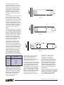
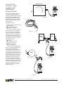
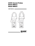
I1
I2
▼
Selecting The
Correct Clamp-On
Current Probe
▼
Selection Guide to Clamp-On Current Probes
Answering the following questions
will help you to select the appropriate
probe for your applications.
4. What type of probe output do
you need or can you work with
(mA, mV, AC, DC, etc.)? Check
the maximum receiver impedance to ensure that the probe
will perform to specifications.
Other factors you may want to consider:
What is the working voltage of the
conductor to be measured? AEMC
probes must not be used above
600V (see specifications)!
What type of output termination do
you need: lead with BNC, lead with
4mm safety banana plugs or jacks
to accept 4mm leads?
Will the probe be used for harmonics
or power measurements? Look at
the frequency specifications and
phase shift specifications.
Lastly, if you cannot find information
you need or would like assistance,
call our application engineers at
(800) 343-1391 or fax us at
(508) 698-2118, or email
[email protected].
Figure 1
Introduction
Clamp-on current probes are designed
to extend the current measuring
capabilities of DMMs, power instruments, oscilloscopes, hand-held
scopes, recorders or loggers and
other diverse instruments. The probe
is “clamped” around the current
carrying conductor to perform noncontact current measurements without
interrupting the circuit under test. The
probe outputs a current or voltage
signal directly proportional to the
measured current, thereby providing
current measuring and displaying
capabilities to instruments with low
current or voltage inputs.
When making a measurement, the
current carrying conductor is not
broken and remains electrically isolated
from the meter input terminals. As a
result, the meter’s low input terminal
may be either floated or grounded. It
is not necessary to interrupt the power
supply when using a clamp-on current
probe for taking measurements, so
costly down time can be eliminated.
True RMS measurements within
the probe frequency
response are possible by
using most AEMC current
probes with a True RMS
multimeter. In most
cases, RMS measurements are not limited by Receptor
the probes, but by the
instrument to which they Production
current
are connected. Best
results are provided by
probes offering inherent
high accuracy, good
frequency response and
minimal phase shift.
AEMC offers the widest selection of
current probes available to measure
AC or DC current. Several AEMC
probes are patented for their unique
circuitry and design and the majority
are UL approved.
AC Clamp-On
Current Probes
Theory of Operation
An AC clamp-on current probe may
be viewed as a variance of a simple
current transformer.
A transformer (Figure 1) is essentially
two coils wound on a common iron
core. A current I1 is applied through
the coil B1, inducing through the
common core a current I2 in the coil
B2. The number of turns of each
coil and the current are related by
N1 x I1 = N2 x I2, where N1 and N2
are the number of turns in each coil.
From this relationship:
I2 = N1/N2 x I1 or I1 = N2/N1 x I1
This same principle is applied to a
clamp-on current probe (Figure 2).
The articulated magnetic core holds
I1
Conductor/cable
N1
I2
▼
3. What size conductor will you clamp
onto? This parameter determines
the probe jaw size needed.
Iron core
→
2. What is the the maximum current
you will measure, and what is
the minimum current you will
measure? Check that the accuracy
at low levels is appropriate, or
select a low current measurement
probe. Most probes perform with
greater accuracy at the upper
end of their range. Several
probes are designed to measure
very low DC or AC.
B2 (N2)
B1 (N1)
▼
1. Determine if you are measuring
AC or DC (DC current probes
are categorized as AC/DC
because they measure both).
Z
A
B2 (N2)
Probe jaws
mA or A
range on
your
instrument
Figure 2
Selection Guide to Clamp-On Current Probes (pdf)
Technical Assistance (800) 343-1391
www.aemc.com
07/02
1 of 5
the coil B2 and clamps onto a
conductor where the current I1 is
flowing. B1 is simply the conductor
where the user is measuring the
current with the number of turns
N1 equal to one. The current probe
clamped around the conductor
provides an output proportional to
the number of turns in its coil B2,
such that:
▼
A
I
AC
I2 (probe output) = N1/N2 x I1 where
N1 = 1 or Probe output = I1/N2
(Number of turns in the probe coil)
Figure 3
It is often difficult to measure I1 directly
because of currents which are too
high to be fed directly into a meter
or simply because breaking into the
circuit is not possible. To provide
a manageable output level multiple
turns are set into the probe coil
bobbin.
▼
Figure 4
1000A
1000mA (1A)
750A
750mA
250A
250mA
10A
10mA
The probe output is connected to a
DMM set on the AC current range to
handle the probe output. Then, to
determine the current in the conductor,
multiply the reading of the DMM by
the ratio (e.g., 150mA read on the
200mA DMM range represents
150mA x 1000 = 150A in the
conductor measured).
▼
Probe Output
Conductor (1000 times less or 1mA/A)
V
AC
There are numerous other ratios
possible: 500:5, 2000:2, 3000:1,
3000:5, etc. for different applications.
The most common application is the
use of a current probe with a digital
multimeter. Take as an example a
current probe with a ratio of 1000:1
(Model SR604) with an output of
1mA/A. This ratio means that any
current flowing through the probe
jaws will result in a current flowing
at the output that is 1000 times smaller:
R
I
The number of turns in the clamp-on
coil are generally simple multiples
(e.g. 100, 500 or 1000). If N2 equals
1000, then the clamp has a ratio of
N1/N2 or 1/1000, which is expressed
as 1000:1. Another way to express
this ratio is to say that the probe
output is 1mA/A - the probe output
is 1mA (I2) for 1A (or 1A @ 1000A)
flowing in the jaw window.
V
I
DC
Figure 5
Current probes may be used with
other instruments with current
ranges, provided that these
instruments have the required input
impedance (see Figure 3).
Current probes may also have AC or
DC voltage outputs to accommodate
current measurements with instruments (loggers, scopes, etc.) with
voltage ranges only (Figures 4 and 5).
This is simply done by conditioning
the current probe output inside the
probe to provide voltage (e.g., Model
MN251). In these cases, the probe
mV output is proportional to the
measured current (e.g., 1mVAC/AAC).
AC/DC Clamp-On
Current Probes
Theory of Operation (Hall effect)
Differing from traditional AC transformers, AC/DC current sensing is
often achieved by measuring the
strength of a magnetic field created by
a current-carrying conductor in a
semiconductor chip using the Hall
effect principle.
When a thin semiconductor (Figure 6)
is placed at right angles to a magnetic
field (B), and a current (Id) is applied
to it, a voltage (Vh) is developed
across the semiconductor. This
Selection Guide to Clamp-On Current Probes (pdf)
Technical Assistance (800) 343-1391
www.aemc.com
07/02
2 of 5
voltage is known as the Hall voltage,
named after the US scientist Edwin Hall
who first reported the phenomenon.
First, since the Hall voltage is not
dependent on a reversing magnetic
field, but only on its strength, the
device can be used for DC measurement. Second, when the magnetic
field strength varies due to varying
current flow in the conductor,
response to change is instantaneous.
Thus, complex AC wave forms may
be detected and measured with high
accuracy and low phase shift.
The basic construction of a probe jaw
assembly is shown in Figure 7, (Note:
one or two Hall generators are used
depending on the type of current probe).
The many AEMC AC/DC Current
Probes were developed based on the
above principle, together with patented
electronic circuitry incorporating signal
conditioning for linear output and a
temperature compensation network.
These have a wide dynamic range
and frequency response with highly
accurate linear output, for application
in all areas of current measurement
up to 1500A. Direct currents can be
measured without the need of
expensive, power consuming shunts,
and alternating currents up to several
kHz can be measured with fidelity to
respond to the requirements of complex
signals and RMS measurements.
→
• Connect the probe to the instrument.
→
When the Hall device drive current
(Id) is held constant, the magnetic
field (B) is directly proportional to the
current in a conductor. Thus, the Hall
output voltage (Vh) is representative
of that current. Such an arrangement
has two important benefits for universal
current measurement.
AC or DC Current
Measurement
Iron core
• Clamp the probe around a single
conductor.
• Select the function and range.
Air
gap
Conductor
Hall
generator
• Read the conductor’s current value.
Example (Figure 8):
Figure 7
The probe outputs are in mV (mVDC
when measuring DC, and mVAC when
measuring AC) and may be connected
to most instruments with a voltage
input, such as DMMs, loggers,
oscilloscopes, hand held scopes,
recorders, etc.
AEMC also offers different technologies
for DC measurements such as in
the K100 and K110 designed to
measure very low DC currents and
using saturated magnetic technology.
AC/DC probes also offer the opportunity
to display or measure True RMS in
AC or AC + DC.
AC: Probe Model: MD303
Ratio: 1000:1
Output: 1mAAC/AAC.
DMM: Set to mAAC range
DMM Reading: 125mAAC
Current in Conductor:
125mA x 1000 = 125AAC
DC: Probe Model: MR521
1mVDC/ADC (Hall sensor)
DMM: Set to mVDC range
DMM Reading: 160mVDC
Current in Conductor: 160ADC
AC: Probe Model: MR411
Output: 1mVAC/AAC (Hall sensor)
DMM: Set to mVAC range
DMM Reading: 120mVAC
Current in Conductor: 120AAC
DC: Micro Probe Model K100
Output: 1mVmA
DMM: Set to mVDC range
DMM Reading: 7.4mVDC
Current in Conductor: 7.4mADC
Power
source
Load
Id
Vh
B
Figure 8
Figure 6
Selection Guide to Clamp-On Current Probes (pdf)
Technical Assistance (800) 343-1391
www.aemc.com
07/02
3 of 5
Low Current,
Process Loops,
Leakage and
Differential
Measurements
Process Loop
I
V
DC
Numerous probes are offered for
low current measurements. For
example, the Models K100 and K110
have a 50mADC sensitivity and the
Model K110 may be used on 4 to
20mA process loops. The selection
guide has a special section on low
current probes.
Figure 9
Examples (Figure 9):
4 to 20mA loop: Probe Model K110
Output: 10mV/mA
DMM: Set to mVDC range
DMM reading: 135mVDC
Loop Current: 13.5mADC (135/10)
Figure 10
Power
source
When the probe is clamped around
two conductors with different
polarities, the resulting reading will
be the difference between the two
currents. If the currents are the same,
the reading will be zero (Figure 11).
When a reading other than zero is
obtained, the reading is the amount
of leakage current on the load. To
measure low currents or leakage,
you need a clamp-on probe which will
measure low values, such as the
Model 2610 (see page 58). Leakage
current on grounds also may be
measured directly with the Model
MN291 (Figure 12).
I
Load
IL
▼
Probe Model: SR604
Ratio: 1000:1
DMM: Set to mAAC range
Turns in Probe Jaw: 10
DMM Reading: 60mAAC
Current in Conductor:
60mA x 1000/10 = 6000mA = 6A
▼
▼
When the current to be measured
is too low for the probe or better
accuracy is required, it is possible to
insert the conductor multiple times
through the probe jaws (Figure 10).
The value of the current is the ratio of
the reading to the number of turns.
I+IL
Motor
IL
1 BE
29RENT PRO
MACN CUR
Figure 11
:
UT AC
TP /A
OU DC
MV
100
Figure 12
© 2002 Chauvin Arnoux®, Inc. d.b.a. AEMC ® Instruments
Technical Assistance (800) 343-1391
Selection Guide to Clamp-On Current Probes (pdf)
www.aemc.com
07/02
4 of 5
Contact Us
United States & Canada:
Chauvin Arnoux®, Inc.
d.b.a. AEMC ® Instruments
200 Foxborough Blvd.
Foxborough, MA 02035 USA
(508) 698-2115 • Fax (508) 698-2118
www.aemc.com
Customer Support - for placing an order, obtaining price & delivery:
[email protected]
Sales Department – for general sales information:
[email protected]
Repair and Calibration Service - for information on repair & calibration, obtaining a user manual:
[email protected]
Technical and Product Application Support –for technical and application support:
[email protected]
Webmaster - for information regarding www.aemc.com:
[email protected]
South America, Australia & New Zealand:
Chauvin Arnoux®, Inc.
d.b.a. AEMC ® Instruments
15 Faraday Drive
Dover, NH 03820 USA
(978) 526-7667 • Fax (978) 526-7605
[email protected]
All other countries:
Chauvin Arnoux
190, rue Championnet
75876 Paris Cedex 18, France
33 1 44 85 45 28 • Fax 33 1 46 27 73 89
[email protected]
Selection Guide to Clamp-On Current Probes (pdf)
Technical Assistance (800) 343-1391
www.aemc.com
07/02
5 of 5