1
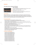
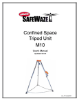
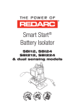
Cable Height Meter User Manual
MODELS 190, 300, 300DT, 300E, 600, 600E, DT80
Contents
Introduction
1
To make a Cable Height Measurement
2
Hints and Guidelines
3
CAL Mode
5
DT Mode
6
Trouble Shooting
7
Performance
8
DT80
9
Using the DT80 with CHM 300DT
10
Warranty
12
Specifications
13
Ordering Information
14
DCF 1254 V1.00
Cable Height Meter
* CHM 300 DT Model only
Introduction
The Suparule™ Cable Height Meter is
a unique, handheld instrument for
measurement of cable sag, cable height
and overhead clearances. It is a
modern alternative to telescopic
measuring poles.
The Cable Height Meter comes in three
models: the CHM 190 for measuring the
height of a single cable, the 300 Series for
measuring the height of up to 3 overhead
cables, and the 600 Series for measuring
6 cables.
The basic 190/300/300DT/ 600 models
measure to a height of 15m (50ft). The 300E
and 600E versions have an increased range
to 23m (75ft).
The CHM 300DT, when used with the DT80,
can also measure horizontal distances up to
45m (150ft)
1
To make a Cable Height Measurement
1. Select the required measurement units
by setting the switch at the back of the
unit to either M (Metric), or I (Imperial). Set
the Measurement Mode switch to the WIRE
position.
2. Press the ON key to power on the unit.
3. Stand directly underneath the cable(s)
to be measured.
4. Allow the temperature reading to stabilise.
5. Press the MEASURE key to take a
measurement. The distance to the first lowest
cable is shown in the Height Measurement
location in the display. If there is more than
one cable present, the difference in height
between each cable is stored in memory.
6. Press the READ key to display each of
the stored cable height differences (Stored
Measurements).
The unit will automatically switch itself off
3 minutes after the last key has been pressed.
2
Hints and Guidelines
Position the unit on the ground, directly
underneath the cable to be measured. Align
the unit in the direction of the cable, with the
cone pointing towards the cable as shown.
When taking wire measurements, ensure
that there are no walls or buildings within a
distance of 2 m (7 ft) either side of the meter,
as reflections from these will distort the
readings. Also ensure there are no trees or
similar overhanging objects in the vicinity.
When measuring more than one wire, ensure
that none of the wires are outside the sonic
beam, as shown in the performance diagram
on page 8.
3
If the wires are not vertically above one
another this could be the case. In this instance
it will be necessary to take a number of
separate readings from different positions.
Water and moisture can cause the sensor to
malfunction. Therefore, the meter should not
be used in rain or snow. If water does get
into the cone, leave it upside down in a dry,
warm area.
If the display shows - - -.- - -, this indicates
a “poor target” and normally happens when the
cables are moving due to wind, etc. Wait until
the wind dies down to get an accurate reading.
The unit operates by transmitting an
ultra-sonic signal towards the wires and
measuring the time it takes to pick up the echo
from that signal. It automatically compensates
for the fact that the speed of sound varies with
temperature by monitoring the ambient
temperature using the internal temperature
sensor. The display continuously shows the
ambient temperature reading. Because the
temperature sensor reacts relatively slowly to
large temperature changes, it is necessary to
wait a minute or so after taking the meter
suddenly from a warm to a cold environment,
e.g. from inside a warm vehicle to a cold
outside, before taking a measurement.
4
CAL Mode (All Models except CHM190 & 300DT)
The Measurement Mode switch allows the
user to periodically check the unit, to ensure
that it is still operating within specification.
For cable height measurement, this switch
should be in the WIRE position. When the
switch is put to the WALL (CAL) position
horizontal measurements to large objects,
e.g. walls, can be taken.
When the unit is first used, a horizontal
reading to an object, e.g. wall, from a
fixed position should be taken. The reading
should be entered, together with the date
into the table below.
Whenever the unit is to be checked
for accuracy a reading should be taken
from the same point, noting the result and
date in the table. If the reading is outside
of specification, the unit should be
returned to your Suparule dealer for
calibration adjustment.
Date
Reading
5
DT Mode (CHM 300DT Model only)
The Measurement Mode switch enables
horizontal distance measurement, in
conjunction with the Suparule™ DT80
product. (DT stands for Dynamic Target.)
Place the DT80 at the point to where the
distance is to be measured. Ensure the DT80
is facing the CHM 300DT. Switch on the DT80.
Set the Measurement Mode switch on the
CHM300DT to DT80 position.
When using a tripod for the CHM300DT, the
temperature sensor on the top of the CHM may
be directly facing the sun, and therefore warm
to a temperature considerably higher than
the air temperature. In this case, it is possible
to manually set the temperature reading,
as follows:
Set the Temperature Mode switch to MAN.
Using the Change Temperature Reading
button, increment or decrement the
temperature reading in the CHM display to
the desired value. (Note: to alter whether this
button increments or decrements, change the
Temperature Mode button to AUTO, and then
back to MAN).
Once the temperature is set, make the
measurement as for WIRE mode, as above.
6
Trouble Shooting
The following is a list of actions to be taken if
the unit is not working properly:
Screen is blank
Check the battery is inserted correctly. Open
the battery door on the bottom rear of the
unit. The battery is inserted with the terminals
on the inside. The + and - symbols on the
battery should match the corresponding
+ and - symbols on the inside of the
battery compartment.
Unit does not measure all wires
Ensure that horizontal distances between
wires are within the sonic beam, as shown
in the performance section on page 8
Incorrect readings
Ensure the Measurement Mode switch is in
the correct position, i.e. WIRE for cable height
measurement, and WALL for horizontal
distance to object measurement.
Ensure no walls or similar obstructions are
within 2 meters either side of the unit, as
reflections from these can interfere with
correct operation. Ensure the temperature
reading has stabilised.
7
Performance
8
DT80
The DT80 is an accessory for use with the
CHM300DT Cable Height Meter, enabling it
to be used for horizontal, as well as vertical
distance measurement.
On its own, the CHM300DT is used for the
measurement of the height of up to 3 overhead
cables, to a maximum of 15m. When used with
the DT80, the CHM300DT can measure
horizontal distances up to 45m.
9
Using the DT80 with the CHM 300DT
1. Position the DT at the point to which the
horizontal distance is to be measured. (Both
the CHM & DT can be mounted on a standard
tripod if necessary, using the threaded hole at
the bottom of each unit).
2. Switch on the DT80.
3. Set the Front/Back switch according to
whether the measurement is to be to
the front or the back of the DT.
4. Set the measurement Mode Switch on the
CHM300DT to DT mode.
10
5. Point the cone of the CHM300DT in the
direction of the DT, and press the measure
button.
6. The distance to the DT will be shown on the
CHM display.
7. To replace the battery, remove rear cover by
removing the 3 cover screws.
11
Warranty
Each unit is guaranteed against malfunction
caused by faulty components or manufacture
for a period of 24 months from date of
purchase (excluding battery).
At Suparule Systems sole discretion, it will
be decided either to repair, modify, or replace
the unit. Should the CHM develop a fault,
return the unit to your authorised dealer,
with Model, Serial No., and full description
of the fault.
We would like to know what you think of
this product. Please contact us with any
comments, criticisms or improvement
suggestions, using the contact details below,
or alternatively send us your comments
directly at www.suparule.com/contact.htm
Please include the serial number of the unit.
SupaRule Systems Limited,
Lonsdale Road,
National Technology Park,
Limerick,
Ireland.
Phone:
Fax:
Email: Web:
12
+353 (0)61 20 10 30
+353 (0)61 33 08 12
[email protected]
www.suparule.com
SPECIFICATIONS
ORDERING INFORMATION
Suparule Systems Limited, Lonsdale Road,
National Technology Park, Limerick, Ireland
Tel: +353 (0) 61 201030, Fax: +353 (0) 61 330812
Email: [email protected], Web: www.suparule.com