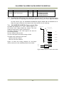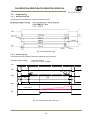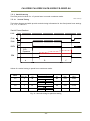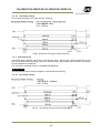
1
CM-200GE/CM-200GE-RA/CB-200GE/CB-200GE-RA
Table of Contents
JAI GigE® Vision Camera operation manuals ...............................................................Introduction .....................................................................................................Before using GigE Vision cameras ............................................................................Software installation...........................................................................................Camera operation ..............................................................................................1. General......................................................................................................2. Camera nomenclature ....................................................................................3. Main Features ..............................................................................................4. Locations and Functions ..................................................................................-
5
5
5
5
6
6
6
7
8
-
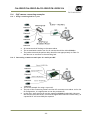
4.1. Locations and functions (CM-200GE/CBN-200GE) .................................................... - 8 4.2. Locations and functions (CM-200GE-RA/CB-200GE-RA) ............................................. - 9 1.1
4.3. Rear panel indicator. ........................................................................... - 10 -
5. Pin Assignment ........................................................................................... - 11 5.1. 12-pin Multi-connector (DC-in/GPIO/Iris Video) ................................................... - 11 5.2. Digital Output Connector for Gigabit Ethernet ..................................................... - 11 -
6. Input and output interface............................................................................. - 12 6.1. Overview .................................................................................................. - 12
6.1.1 LUT (Cross point switch) input and output setting .......................................... - 12
6.1.2 12-bit Counter ..................................................................................... - 13
6.1.3. Pulse Generators ................................................................................... - 13
6.2. Opto-isolated Inputs/Ouputs .......................................................................... - 14
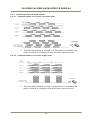
6.2.1 Recommended External Input circuit diagram for customer .............................. - 15
6.2.2 Recommended External Output circuit diagram for customer ............................ - 15
6.2.3 Optical Interface Specifications ................................................................ - 16
6.3. Inputs and outputs table ............................................................................... - 16
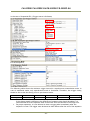
6.4. Configuring the GPIO module (register settings) ................................................... - 17
6.4.1 Input/Output Signal Selector .................................................................... - 17
6.5. Examples of the pulse generator configuration ................................................... - 17
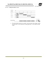
6.5.1 Setting screen of the pulse generator ......................................................... - 17
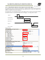
6.5.2 GPIO Plus PWC shutter ........................................................................... - 18
6.5.3 Internal Trigger Generator....................................................................... - 19
-
7. Image output signal ..................................................................................... - 20 7.1. Output image ............................................................................................. - 20
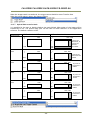
7.2. Vertical Binning (CM-200GE/CM-200GE-RA only). ................................................. - 20
7.3. Digital Video Output (Bit Allocation) ................................................................. - 21
7.3.1 Bit Allocation (Pixel Format / Pixel Type) – CM-200GE/CM-200GE-RA (monochrome) - 21
7.3.1.2 GVSP_PIX_MONO10 (10bit) .................................................................... - 21
7.3.1.3 GVSP_PIX_MONO10_PACKED (10 bit ) ....................................................... - 22
7.3.2 Bit Allocation (Pixel Format / Pixel Type) – CB-200GE/CB-200GE-RA(Bayer) ............... - 22
7.4. CB-200GE/CB-200GE-RA. Bayer mosaic filter....................................................... - 23
7.5. Image timing ............................................................................................. - 24
7.5.1 Horizontal timing .................................................................................. - 24
7.5.2 Vertical timing ..................................................................................... - 24
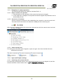
7.5.3 Partial Scanning ................................................................................... - 25
7.5.4 Vertical binning .................................................................................... - 26
7.5.5 Auto Iris Lens video output (12-pin Hirose connector) ..................................... - 27
-
8. Network configuration .................................................................................. - 28 8.1. GigE Vision Standard Interface ........................................................................ - 28
8.2. Equipment to configure the network system ....................................................... - 28
8.2.1 PC .................................................................................................... - 28
8.2.2 Cables ............................................................................................... - 28
8.2.3 Network card (NIC) ................................................................................ - 28
8.2.4 Hub ................................................................................................... - 29
-3-
-