1
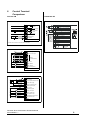
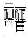
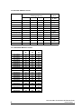
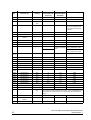
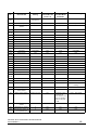
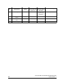
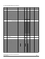
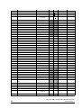
Dinverter 2B to Commander SE Retrofit Guide
Commander SE is the latest product in the family of AC inverters from
Control Techniques, designed to meet today’s customer needs of simple
installation and ease of use, yet also providing a flexible solution to a
diverse range of applications.
This guide is part of a series to provide you with an easy way of retrofitting
existing Control Techniques General Purpose type Drives with Commander
SE.
Due to the potential flexibility of Control Techniques Drives, these retrofit
guides only show the Drives in their default terminal and parameter states.
The Commander SE has 3 levels of parameter menus. Level 1 has only 10
parameters which quickly lets you access these parameters most frequently
required for simple applications.
Level 2 gives access to additional parameters for increased flexibility.
Both Level 1 and Level 2 are accessible via the keypad and display on the
Commander SE.
Level 3 (Extended Menu) parameters gives maximum flexibility of the Drive.
If required, these parameters can only be accessed using serial
communications. The tools we offer for this are:
• The Universal Keypad - a hand held, two line, LCD plain text display
• SESoft - graphical commissioning software and serial communications
lead, SE71
We trust these guides will ease your transition to our latest range of Drives.
Please refer to the user manual of each Drive if more information is required
or contact your local Drive Centre.
Table of Contents
1
I/O Comparison
1
2
Rating Tables
1
2.1
Cabling and fusing differences
2
3
Dynamic Braking Comparison
3
4
General Feature Comparison
4
5
Power Terminal Comparison
5
6
Control Terminal Comparison
6
7
Installation Comparison
7
7.1
Dinverter 2B Drive Dimensions
7
7.2
Commander SE Drive Dimensions
8
7.3
Dinverter 2B Drive Losses
9
7.4
Commander SE Drive Losses
9
8
Parameter Comparison
10
8.1
Dinverter 2B Menu 0 Parameters (for reference) 14
8.2
Commander SE Level 1 and 2 Parameters (for
reference)
Dinverter 2B to Commander SE Retrofit Guide
Issue Number: 1
16
1
I/O Comparison
Dinverter 2B
Commander SE
Analog out - Frequency
Analog out - Load
Analog in - Local speed reference
Analog in - Remote speed reference
Analog in - Torque reference
Analog in - Motor thermistor
Digital in - ET
Digital in - Reset
Digital in - Enable
Digital in - Run Forward
Digital in - Run Reverse
Digital in - Local / Remote
Digital in - Preset speed 1
Digital in - Preset speed 2
Digital in - Jog / Preset speed 3
Digital out - Drive status or At speed
Digital out - Drive running or Minimum speed
Analog out - Frequency
Analog in - Local speed reference
Analog in - Remote speed reference
Digital in - Enable
Digital in - Run forward
Digital in - Run reverse
Digital in - Local / Remote / Preset select
Digital in - Jog / Preset select / Motor thermistor
Digital out - Zero speed
2
Rating Tables
Dinverter 2B
Model
AC supply
Motor power
100%
RMS AC
input
current
AC input
power
100%
RMS
output
current
150%
overload
current for
60 secs
Inrush
current
V ( ±10%)
φ
kW
HP
A
kVA
A
A
A
DIN1220075B
200 ~ 240
1
0.75
1.0
11.3
2.6
4.3
6.5
270
DIN1220150B
200 ~ 240
1
1.5
2.0
18.5
4.2
7.0
10.5
270
DIN1220220B
200 ~ 240
1
2.2
3.0
26.0
6.0
10.0
15.0
270
DIN3220075B
200 ~ 240
3
0.75
1.0
6.9
2.4
4.3
6.5
270
DIN3220150B
200 ~ 240
3
1.5
2.0
11.3
3.9
7.0
10.5
270
DIN3220220B
200 ~ 240
3
2.2
3.0
15.4
5.3
10.0
15.0
270
DIN3380075B
380 ~ 480
3
0.75
1.0
4.2
2.8
2.1
3.2
250
DIN3380110B
380 ~ 480
3
1.1
1.5
5.0
3.3
2.8
4.2
250
DIN3380150B
380 ~ 480
3
1.5
2.0
5.8
3.8
3.8
5.7
250
DIN3380220B
380 ~ 480
3
2.2
3.0
9.0
5.9
5.6
8.4
250
DIN3380300B
380 ~ 480
3
3.0
4.0
11.6
7.6
7.6
11.4
250
DIN3380400B
380 ~ 480
3
4.0
5.3
13.9
9.2
9.5
14.3
250
1
Dinverter 2B to Commander SE Retrofit Guide
Issue Number: 1
Commander SE
MODEL
SE2D200...
075
AC supply voltage and frequency
110
150
220
Single or 3 phase 200 to 240V +/- 10%, 48 to 62Hz
Input displacement factor (cos φ)
>0.97
Nominal motor power - kW
0.75
Nominal motor power - HP
1.0
Output voltage and frequency
1.1
1.5
2.2
2.0
3.0
3 phase, 0 to input voltage, 0 to 1000Hz
100% RMS output current - A
4.3
5.8
7.5
150% overload current for 60 secs - A
6.5
8.7
11.3
Typical full load input current - A* 1ph/3ph
11.0 5.5
Typical inrush current - A**(duration <10ms)
15.1
7.9
19.3
10.6
15
9.6
55
Drive power losses at 230VAC at 6kHz switching frequency - W
54
26.2
13.1
35
69
Weight - kg/lb
88
125
2.75 / 6
Cooling fan fitted
No
Yes
MODEL
SE23400...
075
AC supply voltage and frequency
110
150
220
300
400
3 phase 380 to 480V +/- 10%, 48 to 62Hz
Input displacement factor (cos φ)
>0.97
Nominal motor power - kW
0.75
Nominal motor power - HP
1.0
Output voltage and frequency
1.1
1.5
2.2
2.0
3.0
3.0
4.0
5.0
3 phase, 0 to input voltage, 0 to 1000Hz
100% RMS output current - A
2.1
3.0
4.2
5.8
7.6
9.5
150% overload current for 60 secs - A
3.2
4.5
6.3
8.7
11.4
14.3
Typical full load input current - A*400V, 50Hz/480V, 60Hz
3.6
4.8
6.4
9.3
11
14
Typical inrush current - A** (duration <10ms)
90
60
Drive power losses at 480VAC at 6kHz switching frequency - W
43
57
77
Weight - kg/lb
97
122
158
2.75 / 6
Cooling fan fitted
No
Yes
2.1 Cabling and fusing differences
Drive size
Input
voltage
No. of
input
phases
Din 2B input
fuse rating
SE input fuse
rating
Din 2B input
cable size
SE input
cable size
kW
V
A
A
mm2
mm2
0.75
200 ~ 240
1
16
16
1.5
1.5
1.5
200 ~ 240
1
20
25
2.5
2.5
2.2
200 ~ 240
1
32
32
4.0
4.0
0.75
200 ~ 240
3
10
10
1.0
1.0
1.5
200 ~ 240
3
16
16
1.5
1.5
2.2
200 ~ 240
3
16
20
2.5
2.5
0.75
380 ~ 480
3
6
10
1.0
1.0
1.1
380 ~ 480
3
6
10
1.0
1.0
1.5
380 ~ 480
3
6
10
1.0
1.0
2.2
380 ~ 480
3
10
16
1.0
1.5
3.0
380 ~ 480
3
16
16
1.5
1.5
4.0
380 ~ 480
3
16
20
2.5
2.5
Shading in the above table indicates differences.
Dinverter 2B to Commander SE Retrofit Guide
Issue Number: 1
2
3
Dynamic Braking
Comparison
Dinverter 2B
Commander SE
On board braking on all sizes, connect via
terminals on Con 2.
On board dynamic braking on Sizes 2,3 and 4.
Dynamic braking not possible on Size 1.
Minimum resistance - L.V 33Ω
- H.V 82Ω
MODEL
SE2D200...
110
150
50
100
75
075
Minimum braking resistor value - Ω
Recommended braking resistor
value - Ω
Maximum braking current - A
Resistor peak power rating - kW
9
1.8
MODEL
Minimum braking resistor value - Ω
Recommended braking resistor value - Ω
Maximum braking current - A
Resistor peak power rating - kW
MODEL
Minimum braking resistor value - Ω
Recommended braking resistor
value - Ω
Maximum braking current - A
Resistor peak power rating - kW
4
220
40
50
2.4
11
3.5
SE23200400
30
30
14
5.9
SE23400...
075 110 150 220 300 400
100
75
200
100
10
3.4
12.5
6.9
General Feature
Comparison
Dinverter 2B by default is negative logic and
Commander SE is positive logic. For
Commander SE applications that require
negative logic, simply set p8.29 = 0 and perform
a save routine.
Dinverter 2B
Commander SE
Distance between Drives in a cubicle = 5mm
Distance between Drives in a cubicle = 20mm
Dinverter 2B status relay is N/O as default.
Commander SE status relay is N/C at default. To
change this to N/O set p8.17 = 1 to invert the relay
state.
Dinverter 2B has a torque reference input
terminal (C4).
If torque reference is required then p4.11 will need
to be set to 1 and an analog input re-programmed
to become a torque input, for example set p7.10 =
4.08 for torque input to be terminal 2.
3
Dinverter 2B to Commander SE Retrofit Guide
Issue Number: 1
Dinverter 2B has a motor thermistor input terminal
(A6)
If a motor thermistor input is required first set p8.39
= 1 and then set p8.40 = 1, the thermistor input is
now available on terminal 13.
Dinverter 2B has an external trip terminal (C7)
If this fuction is required then a digital input will
need to be set up, for example to use terminal 12
as ET input. First set p8.39 = 1, then set p8.15 = 1
and p8.25 = 10.32 and perform a save routine.
Terminal 12 is now active as an ET input.
Dinverter 2B has a Reset terminal (C8)
The Drive does have a Reset/Enable terminal (9)
as default, so if the Drive is in a tripped state when
an enable is applied, the Drive will reset
automatically.
However, if a seperate reset terminal is required
then a digital input will have to be sacrificed, for
example, if the JOG terminal 13 is not used in your
application then this can be programmed to be the
reset terminal. Set p8.39 = 1, then set p8.26 =
10.33 and perform a save routine.
Dinverter 2B has an analog voltage output for
frequency or load. Terminal (B1)
As default the Commander SE has a frequency
output on terminal 6. However, it does not have an
individual load output terminal. If this is required,
terminal 6 will have to be programmed. Set
parameter 36 = Ld.
Dinverter 2B has an analog current output for
frequency or load. Terminal (B2).
Commander SE does not have a current output
available.
Dinverter 2B has a status output that indicates
“drive running” or “at speed”. Terminals (A1, A2)
At default Commander SE’s status output indicates
“zero speed”. To change this to “drive running”, set
p8.21 = 10.02. Alternatively, if “at speed” is
required, set p8.21 = 10.06 and perform a save
routine.
Dinverter 2B has 3 preset speed terminals (B8,B9
and B10)
If preset speeds are required parameter 05 will
need to be set to A1.Pr or A2.Pr depending on
which speed reference is required, current or
voltage. 3 preset speeds can be selected by
switching terminals 12 and 13.
Dinverter 2B has a selectable Jog terminal (B10)
As default Commander SE has a Jog input on
terminal 13. However, if preset speeds are required
as well as a Jog input, then a digital input will have
to be sacrificed in order to assign the Jog function.
Dinverter 2B to Commander SE Retrofit Guide
Issue Number: 1
4
5
Power Terminal Comparison
L1
L2 /N
PE
U
V
W
O ptio na l
R F I filte r
M o to r
G ro u n d
O ptio na l
lin e re a cto r
CON 2
F u se s
DBR
C ircu it b re a ke r
/Isola tor
DC+
DC-
M o tor
L 1 L 2 /N
M a ins
S up p ly
S u p p ly
G ro u n d
U
V
W
Commander SE Size 1 power terminal
connections.
NOTE
CON 1
Single phase models: L1 N1 E
Three phase models: L1 L2 L3
On Commander SE Size 1 no DC Bus
connections are available and hence dynamic
braking is not available.
+
Dinverter 2B power terminal connections
Braking
Resistor
DBR
-
L1
L2
L3
PE
U
V
W
Optional RFI
filter
Motor
Ground
Optional
line reactor
Thermal
protection
device
Fuses
Stop
Start/
Reset
Motor
Optional
L1
L2
Mains
Supply
L3
Supply
Ground
Commander SE Size 2 to 4 power terminal
connections.
5
Dinverter 2B to Commander SE Retrofit Guide
Issue Number: 1
6
Control Terminal
Comparison
Dinverter 2B
Commander SE
Status relay
contact
+24V user supply
Drive status
output
0V common
Motor thermistor
0V common
CON 3
Connect A6 to A7 when a motor thermistor is not used
Analog voltage output
Analog current output
RX
RX
TX
Serial
communications
TX
0V common
Preset speed 1
Preset speed 2
Jog / Preset speed 3
CON 4
0V common
Local speed reference input
+10V user supply
Torque reference input
Remote speed input
0V common
External trip input
Drive reset input
Drive enable input
Run forward input
Local/Remote select input
Run reverse input
CON 5
Dinverter 2B to Commander SE Retrofit Guide
Issue Number: 1
6
7
Installation Comparison
7.1 Dinverter 2B Drive Dimensions
Overall Dimensions
Din Rail Mounting Dimensions
DIN-rail mounting
bracket
C
B
DIN-rail
Back-plate
C
D
P
Heatsink
Mounting
foot
D
A
B
N
Case
E
J
7
Dimension
mm
in
A
91
39/16
Dimension
mm
in
B
200
77/8
B
35
13/8
C
293
111/2
C
37.5
11/2
D
56
21/8
D
258
103/16
E
15
F
200
77/8
J
200
77/8
N
8
P
301
Hole diameter
5.5
9/
5/
16
16
117/8
3/
16
Dinverter 2B to Commander SE Retrofit Guide
Issue Number: 1
7.2 Commander SE Drive Dimensions
G
A
B
E
F
F
C
Commander SE Size 1 & 2
4 x M4 holes in heatsink
Commander SE Size 3 & 4
4 x M5 holes in heatsink
D
Drive
Size
A
B
C
D
E
F
G
mm
in
mm
in
mm
in
mm
in
mm
in
mm
in
mm
in
1
191
733/64
175
657/64
102
41/64
130
57/64
181.5
79/64
84
35/16
84
35/16
2
280
111/64
259
103/16
147
525/32
130
57/64
265
107/16
121.5
425/32
121.5
425/32
3
336
137/32
315
1213/32
190
731/64
155
67/64
320
1219/32
172
625/32
164
629/64
4
412
7
389
5
250
397
5
228
217
835/64
16 /32
15 /16
27
9 /32
Dinverter 2B to Commander SE Retrofit Guide
Issue Number: 1
185
9
7 /32
15 /8
63
8 /64
8
7.3 Dinverter 2B Drive Losses
Model
Power dissipation in Watts at specified
switching frequency
Fan air
flow
2.9 kHz
5.9 kHz
8.8 kHz
11.7 kHz
m3/min
DIN1220075B
64
70
88
90
None
DIN1220150B
67
73
93
114
0.72m3
DIN1220220B
82
115
131
140
0.72m3
DIN3220075B
52
61
67
71
None
DIN3220150B
62
72
80
85
0.72m3
DIN3220220B
81
93
108
124
0.72m3
DIN3380075B
41
44
49
61
None
DIN3380110B
46
57
65
72
None
DIN3380150B
55
67
73
89
0.72m3
DIN3380220B
75
89
97
119
0.72m3
DIN3380300B
90
105
120
138
0.72m3
DIN3380400B
110
120
135
148
0.72m3
7.4 Commander SE Drive Losses
9
Drive
3kHz
6kHz
12kHz
W
W
W
SE11200025
17
18
20
SE11200037
22
24
27
SE11200055
34
37
42
SE11200075
50
56
63
SE2D200075
48
54
62
SE2D200110
63
69
80
SE2D200150
82
88
103
SE2D200220
114
125
146
SE23200400
156
174
206
SE23400075
35
43
63
SE23400110
44
57
79
SE23400150
61
77
105
SE23400220
77
97
130
SE23400300
95
122
159
SE23400400
126
158
192
SE33200550
210
230
265
SE33200750
280
305
335
SE33400550
130
190
295
SE33400750
215
270
385
SE43401100
280
400
570
SE43401500
345
495
700
Dinverter 2B to Commander SE Retrofit Guide
Issue Number: 1
8
Parameter Comparison
NOTE
Extended Menu parameters on Commander SE can only be accessed using serial
communications. The tools we offer for this are:
•
•
The Universal Keypad - a hand held, two line, LCD plain text display
SESoft - graphical commissioning software and serial communications lead, SE71
Par.
No.
Description
Dinverter 2B
Default
Setting
Description
Commander SE
(Level 1-2)
Corresponding
Extended Menu
Parameter
Default Setting
Pr0
Min frequency
0Hz
01
1.07
0.0Hz
Pr1
Max frequency
50Hz
02
1.06
50.0Hz
Pr2
Acceleration time
5s/120Hz
03
2.11
5s/100Hz
Pr3
Deceleration time
10s/120Hz
04
2.21
10s/100Hz
Pr4
Timed current limit
150%
N/A
4.07
150%
Pr5
Max cont current
100% FLC
06
5.07
Drive rated current
Pr6
Torque (voltage) boost
5.1%
N/A
5.15
5.0%
Pr7
Slip compensation
0Hz
07
5.08
Pr8
DC injection brake current
150%
N/A
6.06
Upon entering the value
from the motor nameplate
for parameter 5.08, the
Drive will automatically
calculate the correct value
of slip and enable slip
compensation.
100%
Pr9
Serial address
11
43
11.23
1.1
PrA
Fault log
Blank
18
10.20
Blank
PrA-1
Fault log
Blank
19
10.21
Blank
PrA-2
Fault log
Blank
20
10.22
Blank
PrA-3
Fault log
Blank
21
10.23
Blank
PrA-4
Fault log
Blank
N/A
10.24
Blank
PrA-5
Fault log
Blank
N/A
10.25
Blank
PrA-6
Fault log
Blank
N/A
10.26
Blank
PrA-7
Fault log
Blank
N/A
10.27
Blank
PrA-8
Fault log
Blank
N/A
10.28
Blank
PrA-9
Fault log
Blank
N/A
10.29
Blank
Prb
Security code
0
25
11.30
0
b0
Torque or speed
reference selector
1=speed
N/A
4.11
0=speed
b1
Keypad auto or manual
start selector start
1=manual
N/A
N/A
N/A
b2
Stopping mode selector
0=standard
ramp
31
6.01
1=standard ramp
b3
Low speed torque boost
selector
0=auto
b4
Bipolar ref
1=unipolar
Dinverter 2B to Commander SE Retrofit Guide
Issue Number: 1
SE is an open loop vector Drive by default, but fixed boost mode is
attainable by setting p5.14 = 2
SE is unipolar by default. However with the addition of the SE51 option
card, a bipolar speed input is achievable.
10
Par.
No.
Description
Dinverter 2B
Default
Setting
Description
Commander SE
(Level 1-2)
Corresponding
Extended Menu
Parameter
Default Setting
b5
Logic selector
N/A
N/A
N/A
N/A
b6
Speed reference selector
0
N/A
N/A
N/A
b7
Stopping mode selector
0=standard
ramp
31
6.01
1=standard ramp
b8
Display mode selector
0=frequency
22 and 23
4.21 and 5.34
If the mode key is held down
for 2s then the display will
change between frequency
and load.
b9
Terminal or keypad select
1=terminal
05
1.14
A1.A2 terminal
b10
Display time-out mode
0
N/A
N/A
N/A
b11
Remote reference input
selector
4-20mA
16
7.11
4-.20mA
b12
Baud rate selector
4.8
42
11.25
4.8
b13
Parameter reset
0
29
11.43
No
b14
Switching frequency
2.9kHz
37
5.18
PrC
Voltage/frequency profile
50Hz
08
Dependant on
settings of 5.06 and
5.09
N/A
6kHz
Rated voltage
EUR = 400V, USA = 460V
Rated frequency
EUR = 50Hz, USA = 60Hz
Prd
0-10
Menu access
N/A
N/A
N/A
N/A
Pr10
Skip frequency 1
0Hz
N/A
1.29
0.0Hz
Pr11
Skip frequency 2
0Hz
N/A
1.31
0.0Hz
Pr12
Skip frequency 3
0Hz
N/A
1.33
0.0Hz
Pr13
Skip freq. band 1
0.5Hz
N/A
1.30
0.5Hz
Pr14
Skip freq. band 2
0.5Hz
N/A
1.32
0.5Hz
Pr15
Skip freq. band 3
0.5Hz
N/A
1.34
0.5Hz
Prd
10-20
Menu access
N/A
N/A
N/A
N/A
Pr20
Preset speed 1
0Hz
11
1.21
0.0Hz
Pr21
Preset speed 2
0Hz
12
1.22
0.0Hz
Pr22
Preset speed 3
0Hz
13
1.23
0.0Hz
Pr23
Preset speed 4
0Hz
14
1.24
0.0Hz
Pr24
Preset speed 5
0Hz
N/A
1.25
0.0Hz
Pr25
Preset speed 6
0Hz
N/A
1.26
0.0Hz
Pr26
Preset speed 7
0Hz
N/A
1.27
0.0Hz
15
1.05
1.5Hz
Pr27
Jog speed
1.5Hz
b20
Preset speed selector
0=3 presets and
jog
b21
Preset ramp selector
0
N/A
2.10
0=standard
b22
Preset speed reversal
selector
0
N/A
N/A
N/A
b23
Preset ramp selector
0
N/A
N/A
N/A
11
Setting p05=4 will give 4 preset speeds, and a seperate jog terminal can
also be programmed as required. SE can give up to 8 preset speeds (see
Drive set-up for 8 preset speeds in the Commander SE Advanced User
Guide.
Dinverter 2B to Commander SE Retrofit Guide
Issue Number: 1
Par.
No.
Description
Dinverter 2B
Default
Setting
Description
Commander SE
(Level 1-2)
Corresponding
Extended Menu
Parameter
Default Setting
b24 b25
Analog output selectors
0
0 Frequency
N/A
7.33
0 = Frequency
b26
Current loop loss
0 = Trip on loss
N/A
7.11
4 = No trip on loss
b27
Normal running ramp
selector
0
N/A
N/A
N/A
b28
PI control selector
0
N/A
14.08
0
Prd
20-30
Menu access
N/A
N/A
N/A
N/A
Pr30
Preset 1 accel
5s/120Hz
N/A
2.11
5.0s/100Hz
Pr31
Preset 2 accel
5s/120Hz
N/A
2.12
5.0s/100Hz
Pr32
Preset 3 accel
5s/120Hz
N/A
2.13
5.0s/100Hz
Pr33
Preset 4 accel
5s/120Hz
N/A
2.14
5.0s/100Hz
Pr34
Preset 5 accel
5s/120Hz
N/A
2.15
5.0s/100Hz
Pr35
Preset 6 accel
5s/120Hz
N/A
2.16
5.0s/100Hz
Pr36
Preset 7 accel
5s/120Hz
N/A
2.17
5.0s/100Hz
Pr37
Jog accel
0.2s/120Hz
N/A
2.19
0.2s/100Hz
Prd
30-40
Menu access
N/A
N/A
N/A
N/A
Pr40
Preset 1 decel
10s/120Hz
N/A
2.21
10s/100Hz
Pr41
Preset 2 decel
10s/120Hz
N/A
2.22
10s/100Hz
Pr42
Preset 3 decel
10s/120Hz
N/A
2.23
10s/100Hz
Pr43
Preset 4 decel
10s/120Hz
N/A
2.24
10s/100Hz
Pr44
Preset 5 decel
10s/120Hz
N/A
2.25
10s/100Hz
Pr45
Preset 6 decel
10s/120Hz
N/A
2.26
10s/100Hz
Pr46
Preset 7 decel
10s/120Hz
N/A
2.27
10s/100Hz
Pr47
Jog decel
0.2/120Hz
N/A
2.29
0.2s/100Hz
Prd
40-50
Menu access
N/A
N/A
N/A
N/A
Pr50
Number of reset attempts
0
N/A
10.34
0
Pr51
Reset delay
1s
N/A
10.35
1.0s
b50
Status relay selector
0=Drive healthy
N/A
8.27
p8.27 = 10.01 (Drive
healthy)
b51
Fwd/rev key selector
0=disable
26
6.13
Off
b52
Synchronize to a spinning
motor selector
0=disable
33
6.09
0=disable
b53
Status output selector
0=Drive running
N/A
If the Drive running
is required, set
p8.21=10.02. If at or
below min speed is
required, set p8.21
= 10.04
10.03 = Zero speed
b54
Voltage to frequency ratio
selector
0=fixed V/F
32
5.13
0=fixed V/F
b55
Stop/reset key selector
0
N/A
N/A
N/A
b56
Deceleration selector for
non important trips
0
N/A
N/A
N/A
Dinverter 2B to Commander SE Retrofit Guide
Issue Number: 1
12
Par.
No.
Description
Dinverter 2B
Default
Setting
Description
Commander SE
(Level 1-2)
Corresponding
Extended Menu
Parameter
Default Setting
Pr60
Power rating of Drive
N/A
N/A
11.32 can be used
to look at max
output current for
the unit
N/A
Pr61
Drive software version
number
N/A
N/A
11.34 - 11.35
N/A
Pr62
-Pr63
Duration of Drive running
time
N/A
N/A
6.22 - 6.23
N/A
Pr64
DC Bus braking level
750
N/A
N/A
N/A
13
Dinverter 2B to Commander SE Retrofit Guide
Issue Number: 1
8.1 Dinverter 2B Parameters (for reference)
Par. No. Description
Default value
Min
Max
p0
Minimum frequency
0.0
0
p1
p1
Maximum frequency
50 (EUR) / 60 (USA)
[p0]
ULF
p2
Acceleration time
5.0
0.2
999
p3
Deceleration time
10.0
0.2
999
p4
Timed current limit
150
[p5]
150
p5
Maximum continuous current
p6
Torque (Voltage) boost
p7
Slip compensation
p8
DC injection brake current
p9
Serial address
pa
Fault log
pb
Security code
b0
Speed or Torque reference selector
b1
Auto or Manual start selector
1
b2
Stopping mode selector
0
100
10
105
5.1 (EUR) / 3.0 (USA)
0
25.5
0.0
0
25
150 (EUR) / 120 (USA)
40
150
11
0
99
100
1
255
255
4800
9600
Setting 1
Setting 2
0 to 9
Set by keypad
Set by serial comms.
0
1
b3
Low-speed torque boost selector
0
b4
Bipolar select
1
b5
Logic selector
1
b6
Speed reference selector
0
b7
Stopping mode selector
0
b8
Display mode selector
0
b9
Terminal or Keypad mode selector
1
b10
Display time-out mode
b11
Remote reference input selector
4.20
0
b12
Baud rate selector
4.8
b13
Parameter reset
b14
Switching frequency and frequency
range selector
2.9, 120
2.9
120
11.7
960
pc
Maximum-voltage frequency profile
50 (EUR)60 (USA)
ULF
16
ULF
0
pd
Menu selector
0
0
60
p10
Skip frequency 1
0
[p0]
[p1]
p11
Skip frequency 2
0
[p0]
[p1]
p12
Skip frequency 3
0
[p0]
[p1]
p13
Skip band 1
+0.5
+0.5
+0.5
p14
Skip band 2
+0.5
+0.5
+0.5
p15
Skip band 3
+0.5
+0.5
+0.5
p20
Preset speed
0
[p0]
+[p1]
p20
Preset speed
0
[p0]
+[p1]
p21
Preset speed
0
[p0]
+[p1]
p22
Preset speed
0
[p0]
+[p1]
p23
Preset speed
0
[p0]
+[p1]
p24
Preset speed
0
[p0]
+[p1]
Dinverter 2B to Commander SE Retrofit Guide
Issue Number: 1
14
Par. No. Description
Min
Max
p25
Preset speed
0
[p0]
+[p1]
p26
Preset speed
0
[p0]
+[p1]
p27
Jog speed
+1.5 (EUR)
+5.0 (USA)
0
+15
b20
Preset speed selector
0
b21
Preset ramp selector
b21 = 0
b23
Preset ramp selector
b23 = 0
b22
Preset speed reversal selector
b24
Analog output selector
b24 = 0
b25
Analog output selector
b25 = 0
b26
Current-loop loss selector
0
b27
Normal-running ramp selector
0
b28
PI control selector
0
p30
Preset acceleration
5.0
0.2
600
p31
Preset acceleration
5.0
0.2
600
p32
Preset acceleration
5.0
0.2
600
p33
Preset acceleration
5.0
0.2
600
p34
Preset acceleration
5.0
0.2
600
p35
Preset acceleration
5.0
0.2
600
p36
Preset acceleration
5.0
0.2
600
Jog acceleration
0.2
0.2
600
p40
Preset deceleration
10.0
0.2
600
p41
Preset deceleration
10.0
0.2
600
p42
Preset deceleration
10.0
0.2
600
p43
Preset deceleration
10.0
0.2
600
p44
Preset deceleration
10.0
0.2
600
p45
Preset deceleration
10.0
0.2
600
p46
Preset deceleration
10.0
0.2
600
p47
Jog deceleration
0.2
0.2
600
p50
Number of reset attempts
p51
Reset delay
b50
Status relay selector
0
b51
FWD/REV key selector
0
b52
Catch a spinning motor selector
0
b53
Status output selector
0
b54
Voltage-to-frequency ratio selector
0
b55
Stop/Reset key selector
0
b56
Deceleration selector for non-important
trips
0
p60
Power rating of the Drive
p61
Drive software version number
p62
Duration of Drive running time
p63
Duration of Drive running time
p64
DC Bus braking level
Setting 1
Setting 2
0
p37
b60 - b65
15
Default value
0
1
5
1.0
1.0
5.0
540
840
750(EUR)
770(USA)
Factory settings
Dinverter 2B to Commander SE Retrofit Guide
Issue Number: 1
8.2 Commander SE Level 1 and 2 Parameters (for reference)
Par
Description
Default
EUR
01
Min. speed (Hz)
02
Max. speed (Hz)
USA
0.0
50.0
Corresponding
extended menu
parameter
1.07
60.0
1.06
03
Accel. rate (s/100Hz)
5.0
2.11
04
Decel. rate (s/100Hz)
10.0
2.21
05
Ref. select
06
Rated current (A)
07
Rated speed (rpm)
1500
1800
5.08
08
Rated voltage (V)
230 / 400
230 / 460
5.09
L1
11.44
09
Power factor
10
Parameter access
A1.A2
PAd
Drive rating
0.85
L1
1.14
5.07
5.10
11
Preset 1 (Hz)
0.0
1.21
12
Preset 2 (Hz)
0.0
1.22
13
Preset 3 (Hz)
0.0
1.23
14
Preset 4 (Hz)
0.0
1.24
15
Jog. speed (Hz)
1.5
1.05
16
Current mode (mA)
4-.20
7.11
17
Enable negative preset speeds
OFF
1.10
18
Last trip
--
10.20
19
Trip before parameter 18
--
10.21
20
Trip before parameter 19
--
10.22
21
Trip before parameter 20
--
10.23
22
Load display units
Ld
4.21
23
Speed display units
Fr
5.34
24
Customer scaling
25
Security setup
26
Fwd/rev key enable
27
Power up key. ref
0
1.51
28
Parameter cloning
no
11.42
29
Load defaults
no
11.43
30
Ramp mode
1
2.04
31
Stopping mode
1
6.01
32
Variable torque select
OFF
5.13
33
Spinning motor select
0
6.09
34
Positive logic select
35
1.00
11.21
0
11.30
OFF
6.13
On
8.29
Start/Stop logic select
0
6.04
36
Analog output select
Fr
7.33
37
Switching frequency (kHz)
6
5.18
38
Auto tune
0
5.12
39
Rated frequency (Hz)
40
No. of poles
Auto
5.11
41
Serial mode
AnSI
11.24
42
Baud rate
4.8
11.25
43
Serial address
1.1
11.23
44
Software version
--
11.29
*45
Fieldbus node address
0
15.03
*46
Fieldbus baudrate
0
15.04
*47
Fieldbus diagnostics
0
15.06
50.0
60.0
5.06
* Will only appear when parameter 41 is set to FbUS.
Dinverter 2B to Commander SE Retrofit Guide
Issue Number: 1
16


![議事録[PDF:299KB]](http://vs1.manualzilla.com/store/data/006615021_2-ca7646eafef05d2c88ccbd96aa1a3bbf-150x150.png)