1
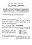
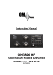
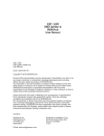
GPRS - Voice - SMS dialer module
for burglary alarm centers
MobilCom-800
The MobilCom-800 GPRS module is a DTMF Contact ID-based GSM module capable
GPRS, GSM voice or SMS communication. It can be installed to alarm centers or can be used as a
standalone unit. The GSM dialer, which is on a 67x80 mm printed circuit, confirms the signals of
burglary alarm centers and forwards them through GPRS, Voice or SMS connection to the
monotoring center. It reports the status of its panic button, test and 3 general inputs in GPRS or
SMS message using Enigma II protocol. The transmitter’s 3 low-current outputs can be switched
from max. 3 mobile phones (based on phone number recognition) by dialing, and it can be
switched to monostable or bistable mode by sending SMS to it. The provider-independent GPRS
transmitter needs 10-15V dc voltage and it can operate in the enclosure of the alarm center, using
its battery. Its magnetic aerial is advised to be positioned on the top of the alarm center's metal
enclosure. The GSM dialer can manage 2 IP addresses, 2 voice phone numbers and 3 SMS
numbers, which can be configured by using our free download software through the computer’s
USB-port. Every parameter, which is necessary for alarm center communication, the module’s
self-employed transmission and remote control, different Contact ID-codes, the CiD-codes of inor outputs and even input commands can be configured in the software. The user can also set IPaddresses here. The 3 inputs of the GPRS transmitter can be configured for Contact ID-codes
freely, so it can function as a stand-alone GPRS or SMS-based GSM transmitter either.
2. The design of MobilCom-800 module
The MobilCom-800 GPRS-based GSM interface module for alarm centers has the
following internal and external functional units:
➢
➢
➢
➢
➢
➢
➢
➢
➢
➢
➢
➢
10-15V power input
12V Tip-Ring current loop
general inputs (3 pcs.)
panic input
reset button / manual test button
relay outputs (3 pcs.)
USB configuration input
8 LED lamp
GSM module
GSM aerial
downloader software
plastic clips for fixing the panel
The module can be installed into the alarm center's metal enclosure box by using the plastic
clips for the boreholes in its four corners. It can receive power supply from the center’s power
supply or battery, its Tip-Ring points connect to the alarm center’s Tip-Ring points and its standing
magnetic aerial (can be replaced) is advised to place on the top of metal case of the alarm center.
MobilCom-800 user's manual
www.mobilcontrol.hu
-
www.sesoft.hu
SeaSoft Ltd.
3.
Connectors of MobilCom-800
The MobilCom-800’s illustration of board and its connections is shown below. It connects to
the alarm center and to its optionals through the connectors on the bottom of the panel, and through
the USB-port (side), the configurations can be downloaded by a computer. On the top there is the
screw-topped aerial connection of the GSM module.
4.
Power supply
The MobilCom-800 module’s power supply is provided by different internal sources. A
different part provides the 11-15V current loop’s noiseless power supply for the alarm center in
order to have more reliable DTMF signal transmission. The GSM module is loaded by the internal
switching power supply. Furthermore, an analog voltage-stabilizator provides voltage for the other
circuits. These three power supplies work correctly if the supply voltage is between 11-15V, and
210 mA maximum load has to be provided to it during the functioning of output relays and the
GSM communication. If the device does not communicate its power consumption will be under 45
mA, so it is suggested to supply the module directly from the battery of the alarm center.
5. Tip-Ring (alarm) input and how it works
The MobilCom-800 monitors the alarm center and its inputs, while it queries the GSMmodule continuously and always keeps it connected to the network. It sends a test code to the
control center in previously configured intervals through the built-up GPRS connection using
Enigma II protocol and waits until the center sends back an acknowlidge signal in similar format.
MobilCom-800 user's manual
www.mobilcontrol.hu
-
www.sesoft.hu
SeaSoft Ltd.
It provides line voltage for the alarm center continuously through the connected Tip-Ring points to
the green treminal blocks. It start a dial tone and simulates real phone line when it is in on-hook
status. The alarm center sends Contact ID reports to the monitoring center through the GPRS
transmitter using GPRS connection. Transmission and ancknowlidge continues until the alarm
center’s event-buffer empties. In the same time dedicated and general inputs can change, and it
manages and forwards them in a similar way - as it did with the alarm center transmission - to the
monitoring center.
6.
How the stand-alone inputs work
The MobilCom-800 GPRS module has a test and reset pushbutton. By pushing the
test/reset button for less than 3 seconds, it sends a test- and restoral code to the monitoring center
according to configuration. If the button is pushed for more than 3 seconds the module resets, and
it reports to monitoring center the module's restarts action. An auxiliary panic button indicated
with “P” can be connected the green PCB terminal blocks, even pushing then releasing the panic
button - connected between the input and ground – is also reported by the GSM transmitter. The 3
general inputs switch to 0V level (connected to ground), and they are wired out on the green
terminal blocks marked “In1”, “In2”, “In3”.
7.
Relay outputs
The 3 relay outputs of the GSM transmitter can be operated by sending SMS or by calling it.
These relay outputs can be turned on or off separately by previously defined SMS’s during configuration. Changing the outputs generates events, similarly to the inputs. The outputs no. 1 and 2
can be switched only by sending SMS in bistable mode. Accordingly to the sent SMS, the NO type
relay connected to the orange terminal blocks turns on or off. The content of the sent SMS defines
the command, which keeps the device in this status until it hasn’t received another command with
the opposite content. The relay no.2 is also bistable, and can be switched only by SMS. It operates
similarly to the output no.1, but it is connected to the normally closed (NC) switch, so the SMS
with the ‘switch on’ order the relay open the circuit. The output no.3 can operated by a call (phone
number recognition), or by an SMS command. The relay changes to bistable mode when the relay
switch time is setted to 0, so it switches on when an SMS command is sent and stays this way until
a turn-off order is received. The relay alternates when calling it, which means that if it was
switched on it releases, or if it was released, it switches on. The status of the relay is derived from
the initiated call, because the relay switches on after a previously configured number of rings, and
switches off after a previously configured number of rings. The relay no. 3 changes to monostable
mode in case of configuring the switch on time to 1-99 seconds, and an SMS command or a call
initiated from a configured number switches on for a configured time. After this configured time
expires the relay switches off. These relays have a max. load of 48V and 1A current. It is capable of
arming or disarming the center, giving service to the central panels of the center, like light-sound
signal, zone-bypass, resetting etc.
8.
Meaning of LED-diodes
The communication can be followed up by the 8 coloured led. It can be learned quite easily
after a little practice. The lower, green HB (heartbit, life-signal) LED shows us whether the module
MobilCom-800 user's manual
www.mobilcontrol.hu
-
www.sesoft.hu
SeaSoft Ltd.
is able to function, normally it blinks with 1-second intensity. The red “St” LED shows how the
industrial module operates, the blinking depends on the actual mode of the turned on module.
The actual status of alarm center can be seen on the red “HK”
(“Hook”) LED. When the alarm center is in onhook status and it
tries to communicate the LED will light up. The process of
DTMF communication is shown by the yellow LED-diode named
“DT”, which lights up when dialing and when sending an event
during the communication, according to the sent characters. The
red “HS” LED lights up in case of so-called handshake or kiss-off
signals. These signals are sent by the transmitter module to the
alarm center at the beginning and the end of communication. The
transmit-receive process of GPRS communication is shown by the
yellow LEDs named “Tx” (transmit) and “Rx” (receive). The
uppermost multi-colored LED, “Sn” indicates the status of the
GPRS dialer. If this led lights in red, the module is not connected
to the network. If the LED is yellow, the GSM is connected to the
network, but has no connection with the GPRS server of the
monitoring center. If the LED glows with green light, it is
connected to the network and the server. These LEDs provide
useful information about how the module operates, its current
state and the complete process of GPRS communication. With a
little practice, they make installation of the module much easier.
9. Connecting the MobilCom-800 GPRS transmitter
Connection of MobilCom-800 panel to the alarm center has to be done according to the
illustration. Connecting the power supply and Tip-Ring inputs is necessary while the panic input,
remote arm or disarm and GSM gate-opener functions can be connected optionally.
MobilCom-800 user's manual
www.mobilcontrol.hu
-
www.sesoft.hu
SeaSoft Ltd.
10. Configuring the MobilCom-800 module
Configuring the GPRS transmitter module can be done by using our free software through a
USB-port of a computer. The software doesn’t need to be installed, you have to only copy it into a
folder created for the downloader and start it under the
well-known Windows XP
or Win7 operating system.
Insert the PIN card (remove
the PIN code before it) into
the socket, then connect the
powered up device to the
USB-port. First install the
module drivers in order to
make them recognizable
automatically by Win-XP
or higher operating system.
After this step it has to identify which serial port is connected to the device. It's possible the use the
autodetect function or it can be found manually too. For example to do it this way in Windows XP:
Control Panel -> System -> Hardware -> Devices and Printers -> Ports (Com)
Here it can be found the device now, indicating that to which serial port it's connected
connected between the com1... com99 range.
Then by starting the software, it is necessary
to configure this Com value as a hardware setting. The software has a file autoload function, but in
case it is advised to load the Default.cfg file after starting the software, which helps as a tutorial for
the correct configuration. The file Default.cfg file can be found in the File Menu Open part of the
software, from where you can also load saved files. According to the loaded file, the Device ID is
on the first General page (here: 1234), which is suggested to change to your alarm center user ID.
You can add 1-99 as a Test code time, which gives (in minutes) that between what intervals must
the panel send test code. A very low value of time of Automatic test code generates larger data
transfer rate, which may lead to unwanted communication expenses. In the Inputs menu it can be
configured the CiD value of automatic test code along with the event (here: 606). The Cid code of
the automatic testcode must be the same as the applyed code table of the monitoring center. The
automatic testcode is only event-like, it does not have restore status. The start/restart code field is
also only event-like, also so it does not have restore status. The panel sends this code automatically
MobilCom-800 user's manual
www.mobilcontrol.hu
-
www.sesoft.hu
SeaSoft Ltd.
if it is powered up in the first time, or
it is powered up after a power outage.
You always have to follow the codes
received from the monitoring center.
In the group number field you can
find the group number of Cid events
sent at the activation of each input.
Its value can be optional. This group
number will be in every Contact ID
report made by the panel. In the field
of zone number you can configure
the zone numbers of Cid events sent
at the input activations. Their value is
optional, but the value will appear in
every Cid report made by the panel
as a zone number. In the Manual
Testcode and Panic Button fields
you can find the CiD's belonging to
the two events: the event code (here:
first number 1) and the restore code
(here: first number 3). These codes are generated automatically, in accord with the configured user
ID, group number and zone number
codes in case of input changes. You
have to complete the fields of the
three general inputs similarly,
because their change generates CiDreport, as the previously introduced
dedicated inputs. You can designate
the SMS commands that switches
the GPRS transmitter outputs. You
can assign 2 (max. 15 chars. long)
command for each output, which are
carried out by relays if send them.
(on/off) The commands must be
maximum 15 characters long and use
use characters without accent due to
the different character coding of
mobile phones. Each command has
to be configured (even when they are
not used), an they have to be
different. Here you can configure the
swith on time of the relay no. 3. Its
value can be between 0..99 secs in
both modes. One of its modes will be bistable when the configured value is 0 sec. The relay
switches on for the SMS switch on command or for an initiated call, and it stays switched on until
it receives a new command. If you configure the values between 1..99 secs, the relay turns to
astable mode, which means that it switches on for SMS command or calling it and it stays switched
on until the configured time elapses. You can configure how many rings are needed for the relay to
open the circuit in bistable mode, and how many rings are needed for the relay to close the circuit
also in bistable mode. The different ringing numbers helps you check whether the output no. 3 is
MobilCom-800 user's manual
www.mobilcontrol.hu
-
www.sesoft.hu
SeaSoft Ltd.
switched on or off. You can configure the parameters necessary for GPRS communication in the
GPRS settings menu. Connection to the server can be configured by IP-addresses. You have to
enter the APN correctly given by your provider into the first field, which must be different in every
provider. Enter the fix IP address of the
server of monitoring center into the field,
and apply the usual 4x3 character decimal
format. In the next field (Port) you have to
add the Port which receives data configured
by the system administrator of monitoring
center. The modul tries to communicate
with the 2nd server too if it failed to
communicate with the first server, so it is
important to configure that either. If there is
only one server, enter the first IP-address to
both fields. Then the MobilCom-800 GPRS
dialer module tries to communicate with
the first server twice, when the first attempt
failed. In the SMS Settings Menu you can
add 3 phone numbers initiated with + sign and the country code. The GPRS module will send an
SMS message containing the CiD-report to the first number. These phone number are the ones that
can operate the module’s outputs remotely
by dialing it. You can configure the parameter that limits the maximum number of
SMS sent by the device in order to avoid
high SMS expenses, when, for example,
GPRS service is limited or absent for a
longer time. The Maximum SMS Number
setting means that service stops for a while
when the device reached this number. The
number of SMS Disable Time configures
that for how many minutes shallbe the Sms
sending disabled. The secondary (SMS-based) transmission works only for the first number, the
other numbers are for the remote controlling of relay outputs. The dialer discards every call from
unregistered numbers and the GPRS transmitter forwards every Sms from unknown phone numbers
to the no. 1 SMS number and it
does the same with SMS messages
from the provider. In the Voice
Settings menu the secondary
transmission will be forwarded to
the Voice 1 phone number. You
can give two phone numbers in the
Voice Settings, the first has to be
the provider’s primary number with
international format, with + prefix
and with country code. If there is no GPRS connection, the GPRS module has two secondary
options for communication. SMS or DTMF-based reports can be specified for the module. While
the GPRS module is primarily developed for GPRS communication, you should only allow one of
the two secondary options, in order to receive event reports in the shortest time! You can configure
this in the SMS Settings and Voice Settings, by setting SMS sending ON/OFF or Voice ON/OFF.
MobilCom-800 user's manual
www.mobilcontrol.hu
-
www.sesoft.hu
SeaSoft Ltd.
11. Installing the MobilCom-800 modul
It is advised to configure the MobilCom-800 module previously, but if it is necessary, it is
possible to configure it at the place of installation. We suggest to install the module in the order
below:
1
First remove the PIN code from the SIM card, then insert it into the card socket on the
module. After that, fix it in its final place by using the supplied plastic clips
2
Connect the small standing magnetic aerial supplied with short RG174 koax cable
before powering up the device into the screw-topped jack on the panel.
3
The Tip and Ring points are the points going towards the phone line output of the alarm
center. You have to connect the alarm center here, if the module does not operate in
autonome-mode.
4
You can optionally connect a panic button, because the module reports it in 1-2 seconds.
5
Connecting the In1..In3 inputs in arbitrary order, depending on how many inputs would
you like to use. The inputs switch to a voltage above 8V, their common negative point is
Com, so it has to be connected to the common (ground) point. You can connect
thermostat, for example, to the general inputs, and heater, boiler etc. to the outputs.
To control devices supplied by 230V, apply always high-current high-voltage relay !
MobilCom-800 user's manual
www.mobilcontrol.hu
-
www.sesoft.hu
SeaSoft Ltd.
4
You can optionally connect a panic button, because the module reports it in 1-2 seconds.
6
Connecting the Out1...Out3 low-current relays optionally. The NO or NC outputs and the
output no. 3 can be operated by dialing, so choosing them and their connection needs
more attention. The gate-opener function, the alarm center remote turn off/on function,
or heater, boiler for outputs etc. can be connected this way (through high current relay).
7
The panel’s power input is provided by the 12V and Gnd inputs. It is advised to connect
them last. 11V-15V voltage can be connected to the power inputs. If the voltage is below
this value, the communication with the alarm center will be unreliable, and if it is above
this value, the module could be damaged. It is recommended to supply the module by
the alarm center's battery.
8
Check the positioning of the aerial in order to provide sufficient signal to the GSM
module, because GPRS data transmission (contrary to SMS) is a highly signal-dependant
mode. It is very important to remove the PIN code from the SIM card (by using an
ordinary handphone) before turning the module on!
9
After wiring the module, it has to be powered up. If the module is configured, it will be
operational in the future. If it is not, it has to be configured after turning it on through its
USB-port. It is advised to save the downloaded parameters to know what parameters has
been configured to the module. From then, the module is able to communicate.
10
The operating GPRS module can be tested by pushing shortly the test button on top of
the device, or by sending a signal to the communication channel (if the alarm center is
connected to it).
11
You can configure the equipped device and download its configuration in the above
written order.
9. Specifications:
Supply voltage:
Min Mean
Max
11 V
15 V
Size of board:
80 x 67 mm
Type of dedicated inputs :
test, panic
18 V
Number of common inputs:
3
Input current of inputs:
1 mA
Nimber of relay outputs:
3
Output voltage load:
48 V
Type of GSM module:
Huawei EM310
Output current load:
1A
Type of aerial:
(900/1800)
Communication format:
Contact ID
Maximal current cons:
Input voltage on inputs
Loop voltage on Tip-Ring:
Loop current of Tip-Ring:
Input delay time:
MobilCom-800 user's manual
13.2V
32 mA 40mA 210 mA
8V
12V
13 V
12mA 14 mA
GSM modes:
17 mA
Applied GPRS protocol
20 ms
www.mobilcontrol.hu
-
www.sesoft.hu
GPRS, Voice, SMS
Enigma II.
SeaSoft Ltd.