1
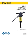
GD50
HYDRAULIC
GROUND ROD DRIVER
USER MANUAL
Safety, Operation and Maintenance
© 2014 Stanley Black & Decker, Inc.
New Britain, CT 06053
U.S.A.
39234 8/2014 Ver. 7
TABLE OF CONTENTS
SAFETY SYMBOLS...................................................................................................................................................4
SAFETY PRECAUTIONS...........................................................................................................................................5
TOOL STICKERS & TAGS.........................................................................................................................................6
HOSE TYPES.............................................................................................................................................................7
HOSE RECOMMENDATIONS...................................................................................................................................8
FIGURE 1. TYPICAL HOSE CONNECTIONS........................................................................................................8
HTMA REQUIREMENTS............................................................................................................................................9
OPERATION.............................................................................................................................................................10
FIGURE 2. CONNECTING THE VALVE............................................................................................................... 11
CHARGING THE ACCUMULATOR..........................................................................................................................12
FIGURE 3. CHARGING THE ACCUMULATOR....................................................................................................12
TOOL PROTECTION & CARE.................................................................................................................................13
TROUBLESHOOTING.............................................................................................................................................14
SPECIFICATIONS....................................................................................................................................................15
SERVICE TOOLS.....................................................................................................................................................15
GD50 PARTS ILLUSTRATION.................................................................................................................................16
GD50 PARTS LIST...................................................................................................................................................17
IMPORTANT
To fill out a Product Warranty Validation form, and for information on your warranty,
visit Stanleyhydraulics.com and select the Company tab, Warranty.
(NOTE: The warranty Validation record must be submitted to validate the warranty).
SERVICING: This manual contains safety, operation, and routine maintenance instructions. Stanley Hydraulic Tools
recommends that servicing of hydraulic tools, other than routine maintenance, must be performed by an authorized
and certified dealer. Please read the following warning.
WARNING
SERIOUS INJURY OR DEATH COULD RESULT FROM THE IMPROPER REPAIR OR
SERVICE OF THIS TOOL.
REPAIRS AND / OR SERVICE TO THIS TOOL MUST ONLY BE DONE BY AN
AUTHORIZED AND CERTIFIED DEALER.
For the nearest authorized and certified dealer, call Stanley Hydraulic Tools at the number listed on the back of this
manual and ask for a Customer Service Representative.
GD50 User Manual ◄ 3
SAFETY SYMBOLS
Safety symbols and signal words, as shown below, are used to emphasize all operator, maintenance and repair actions which, if not strictly followed, could result in a life-threatening situation, bodily injury or damage to equipment.
This is the safety alert symbol. It is used to alert you to potential personal injury
hazards. Obey all safety messages that follow this symbol to avoid possible
injury or death.
DANGER
This safety alert and signal word indicate an imminently hazardous situation
which, if not avoided, will result in death or serious injury.
WARNING
This safety alert and signal word indicate a potentially hazardous situation
which, if not avoided, could result in death or serious injury.
CAUTION
This safety alert and signal word indicate a potentially hazardous situation
which, if not avoided, could result in death or serious injury.
CAUTION
This signal word indicates a potentially hazardous situation which, if not avoided, may result in property damage.
NOTICE
This signal word indicates a situation which, if not avoided, will result in damage
to the equipment.
IMPORTANT
This signal word indicates a situation which, if not avoided, may result in damage to the equipment.
Always observe safety symbols. They are included for your safety and for the protection of the tool.
LOCAL SAFETY REGULATIONS
Enter any local safety regulations here. Keep these instructions in an area accessible to the operator and maintenance personnel.
4 ► GD50 User Manual
SAFETY PRECAUTIONS
Tool operators and maintenance personnel must always
comply with the safety precautions given in this manual
and on the stickers and tags attached to the tool and
hose.
•
To avoid personal injury or equipment damage, all
tool repair, maintenance and service must only be
performed by authorized and properly trained personnel.
These safety precautions are given for your safety. Review them carefully before operating the tool and before
performing general maintenance or repairs.
•
Always replace parts with replacement parts recommended by Stanley Hydraulic Tools.
•
Check fastener tightness often and before each use
daily.
Supervising personnel should develop additional precautions relating to the specific work area and local
safety regulations. If so, place the added precautions in
the space provided in this manual.
The GD50 Hydraulic Rod Driver will provide safe and
dependable service if operated in accordance with the
instructions given in this manual. Read and understand
this manual and any stickers and tags attached to the
tool and hoses before operation. Failure to do so could
result in personal injury or equipment damage.
•
Operator must start in a work area without bystanders. The operator must be familiar with all prohibited
work areas such as excessive slopes and dangerous terrain conditions.
•
Establish a training program for all operators to ensure safe operation.
•
Do not operate the tool unless thoroughly trained or
under the supervision of an instructor.
•
Always wear safety equipment such as goggles, ear
and head protection, and safety shoes at all times
when operating the tool.
•
Do not inspect or clean the tool while the hydraulic
power source is connected. Accidental engagement
of the tool can cause serious injury.
•
Always connect hoses to the tool hose couplers before energizing the hydraulic power source. Be sure
all hose connections are tight.
•
Do not operate the tool at oil temperatures above
140 °F/60 °C. Operation at higher temperatures can
cause higher than normal temperatures at the tool
which can result in operator discomfort.
•
Do not operate a damaged, improperly adjusted, or
incompletely assembled rod driver.
•
Do not weld, cut with an acetylene torch, or hardface
the rod driver anvil or guide housing.
GD50 User Manual ◄ 5
TOOL STICKERS & TAGS
GD50 ROD DRIVER
Stanley Hydraulic Tools
Division of The Stanley Works
3810 SE Naef Road
Milwaukie, Oregon 97267 USA
FLOW: 26-34 LPM/7-9 GPM
PRESS: 105-140 BAR
1500-2000 PSI
ACCUMULATOR CHG:
42 BAR/600 PSI NITROGEN
37425
Name Tag
NOTE:
THE INFORMATION LISTED
ON THE STICKERS SHOWN,
MUST BE LEGIBLE AT ALL
TIMES.
REPLACE DECALS IF
THEY BECOME WORN OR
DAMAGED. REPLACEMENTS
ARE AVAILABLE FROM
YOUR LOCAL STANLEY
DISTRIBUTOR.
The safety tag (P/N 15875) at right is
attached to the tool when shipped from
the factory. Read and understand the
safety instructions listed on this tag before
removal. We suggest you retain this tag and
attach it to the tool when not in use.
D A N G E R
1.
FAILURE TO USE HYDRAULIC HOSE LABELED AND CERTIFIED AS NON-CONDUCTIVE WHEN USING HYDRAULIC
TOOLS ON OR NEAR ELECTRICAL LINES MAY RESULT IN
DEATH OR SERIOUS INJURY.
BEFORE USING HOSE LABELED AND CERTIFIED AS NONCONDUCTIVE ON OR NEAR ELECTRIC LINES BE SURE THE
HOSE IS MAINTAINED AS NON-CONDUCTIVE. THE HOSE
SHOULD BE REGULARLY TESTED FOR ELECTRIC CURRENT LEAKAGE IN ACCORDANCE WITH YOUR SAFETY
DEPARTMENT INSTRUCTIONS.
2.
A HYDRAULIC LEAK OR BURST MAY CAUSE OIL INJECTION INTO THE BODY OR CAUSE OTHER SEVERE
PERSONAL INJURY.
A.
DO NOT EXCEED SPECIFIED FLOW AND PRESSURE
FOR THIS TOOL. EXCESS FLOW OR PRESSURE MAY
CAUSE A LEAK OR BURST.
B.
DO NOT EXCEED RATED WORKING PRESSURE OF
HYDRAULIC HOSE USED WITH THIS TOOL. EXCESS
PRESSURE MAY CAUSE A LEAK OR BURST.
C. CHECK TOOL HOSE COUPLERS AND CONNECTORS
DAILY FOR LEAKS. DO NOT FEEL FOR LEAKS WITH
YOUR HANDS. CONTACT WITH A LEAK MAY RESULT
IN SEVERE PERSONAL INJURY.
D A N G E R
D. DO NOT LIFT OR CARRY TOOL BY THE HOSES. DO
NOT ABUSE HOSE. DO NOT USE KINKED, TORN OR
DAMAGED HOSE.
3.
MAKE SURE HYDRAULIC HOSES ARE PROPERLY CONNECTED TO THE TOOL BEFORE PRESSURING SYSTEM.
SYSTEM PRESSURE HOSE MUST ALWAYS BE CONNECTED TO TOOL “IN” PORT. SYSTEM RETURN HOSE
MUST ALWAYS BE CONNECTED TO TOOL “OUT” PORT.
REVERSING CONNECTIONS MAY CAUSE REVERSE
TOOL OPERATION WHICH CAN RESULT IN SEVERE
PERSONAL INJURY.
4.
DO NOT CONNECT OPEN-CENTER TOOLS TO CLOSEDCENTER HYDRAULIC SYSTEMS. THIS MAY RESULT IN
LOSS OF OTHER HYDRAULIC FUNCTIONS POWERED BY
THE SAME SYSTEM AND/OR SEVERE PERSONAL INJURY.
5.
BYSTANDERS MAY BE INJURED IN YOUR WORK AREA.
KEEP BYSTANDERS CLEAR OF YOUR WORK AREA.
6.
WEAR HEARING, EYE, FOOT, HAND AND HEAD PROTECTION.
7.
TO AVOID PERSONAL INJURY OR EQUIPMENT DAMAGE,
ALL TOOL REPAIR MAINTENANCE AND SERVICE MUST
ONLY BE PERFORMED BY AUTHORIZED AND PROPERLY
TRAINED PERSONNEL.
I M P O R T A N T
I M P O R T A N T
READ OPERATION MANUAL AND
SAFETY INSTRUCTIONS FOR THIS
TOOL BEFORE USING IT.
READ OPERATION MANUAL AND
SAFETY INSTRUCTIONS FOR THIS
TOOL BEFORE USING IT.
USE ONLY PARTS AND REPAIR
PROCEDURES APPROVED BY
STANLEY AND DESCRIBED IN THE
OPERATION MANUAL.
USE ONLY PARTS AND REPAIR
PROCEDURES APPROVED BY
STANLEY AND DESCRIBED IN THE
OPERATION MANUAL.
TAG TO BE REMOVED ONLY BY
TOOL OPERATOR.
TAG TO BE REMOVED ONLY BY
TOOL OPERATOR.
SEE OTHER SIDE
SEE OTHER SIDE
SAFETY TAG P/N 15875 (Shown smaller then actual size)
6 ► GD50 User Manual
HOSE TYPES
The rated working pressure of the hydraulic hose must be equal to or higher than the relief valve setting on the hydraulic system. There are three types of hydraulic hose that meet this requirement and are authorized for use with
Stanley Hydraulic Tools. They are:
Certified non-conductive — constructed of thermoplastic or synthetic rubber inner tube, synthetic fiber braid
reinforcement, and weather resistant thermoplastic or synthetic rubber cover. Hose labeled certified nonconductive is the only hose authorized for use near electrical conductors.
Wire-braided (conductive) — constructed of synthetic rubber inner tube, single or double wire braid reinforcement, and weather resistant synthetic rubber cover. This hose is conductive and must never be used near
electrical conductors.
Fabric-braided (not certified or labeled non-conductive) — constructed of thermoplastic or synthetic rubber inner tube, synthetic fiber braid reinforcement, and weather resistant thermoplastic or synthetic rubber cover. This
hose is not certified non-conductive and must never be used near electrical conductors.
HOSE SAFETY TAGS
To help ensure your safety, the following DANGER tags are attached to all hose purchased from Stanley Hydraulic
Tools. DO NOT REMOVE THESE TAGS.
If the information on a tag is illegible because of wear or damage, replace the tag immediately. A new tag may be
obtained from your Stanley Distributor.
D A N G E R
D A N G E R
1.
FAILURE TO USE HYDRAULIC HOSE LABELED AND CERTIFIED AS NON-CONDUCTIVE
WHEN USING HYDRAULIC TOOLS ON OR NEAR ELECTRIC LINES MAY RESULT IN
DEATH OR SERIOUS INJURY.
FOR PROPER AND SAFE OPERATION MAKE SURE THAT YOU HAVE BEEN PROPERLY TRAINED IN CORRECT PROCEDURES REQUIRED FOR WORK ON OR AROUND
ELECTRIC LINES.
2.
BEFORE USING HYDRAULIC HOSE LABELED AND CERTIFIED AS NON-CONDUCTIVE
ON OR NEAR ELECTRIC LINES. WIPE THE ENTIRE LENGTH OF THE HOSE AND FITTING WITH A CLEAN DRY ABSORBENT CLOTH TO REMOVE DIRT AND MOISTURE AND
TEST HOSE FOR MAXIMUM ALLOWABLE CURRENT LEAKAGE IN ACCORDANCE WITH
SAFETY DEPARTMENT INSTRUCTIONS.
3.
DO NOT EXCEED HOSE WORKING PRESSURE OR ABUSE HOSE. IMPROPER USE
OR HANDLING OF HOSE COULD RESULT IN BURST OR OTHER HOSE FAILURE.
KEEP HOSE AS FAR AWAY AS POSSIBLE FROM BODY AND DO NOT PERMIT DIRECT
CONTACT DURING USE. CONTACT AT THE BURST CAN CAUSE BODILY INJECTION
AND SEVERE PERSONAL INJURY.
4.
HANDLE AND ROUTE HOSE CAREFULLY TO AVOID KINKING, ABRASION, CUTTING, OR
CONTACT WITH HIGH TEMPERATURE SURFACES. DO NOT USE IF KINKED. DO NOT
USE HOSE TO PULL OR LIFT TOOLS, POWER UNITS, ETC.
5.
CHECK ENTIRE HOSE FOR CUTS CRACKS LEAKS ABRASIONS, BULGES, OR DAMAGE TO COUPLINGS IF ANY OF THESE CONDITIONS EXIST, REPLACE THE HOSE
IMMEDIATELY. NEVER USE TAPE OR ANY DEVICE TO ATTEMPT TO MEND THE HOSE.
6.
AFTER EACH USE STORE IN A CLEAN DRY AREA.
SEE OTHER SIDE
SIDE 1
SEE OTHER SIDE
(Shown smaller than actual size)
DO NOT REMOVE THIS TAG
DO NOT REMOVE THIS TAG
THE TAG SHOWN BELOW IS ATTACHED TO “CERTIFIED NON-CONDUCTIVE” HOSE
SIDE 2
D A N G E R
D A N G E R
1.
DO NOT USE THIS HYDRAULIC HOSE ON OR NEAR ELECTRIC LINES. THIS HOSE IS
NOT LABELED OR CERTIFIED AS NON-CONDUCTIVE. USING THIS HOSE ON OR NEAR
ELECTRICAL LINES MAY RESULT IN DEATH OR SERIOUS INJURY.
5.
CHECK ENTIRE HOSE FOR CUTS CRACKS LEAKS ABRASIONS, BULGES, OR DAMAGE TO
COUPLINGS IF ANY OF THESE CONDITIONS EXIST, REPLACE THE HOSE IMMEDIATELY.
NEVER USE TAPE OR ANY DEVICE TO ATTEMPT TO MEND THE HOSE.
2.
FOR PROPER AND SAFE OPERATION MAKE SURE THAT YOU HAVE BEEN PROPERLY
TRAINED IN CORRECT PROCEDURES REQUIRED FOR WORK ON OR AROUND ELECTRIC LINES.
6.
AFTER EACH USE STORE IN A CLEAN DRY AREA.
3.
DO NOT EXCEED HOSE WORKING PRESSURE OR ABUSE HOSE. IMPROPER USE OR
HANDLING OF HOSE COULD RESULT IN BURST OR OTHER HOSE FAILURE. KEEP HOSE
AS FAR AWAY AS POSSIBLE FROM BODY AND DO NOT PERMIT DIRECT CONTACT
DURING USE. CONTACT AT THE BURST CAN CAUSE BODILY INJECTION AND SEVERE
PERSONAL INJURY.
4.
HANDLE AND ROUTE HOSE CAREFULLY TO AVOID KINKING, CUTTING, OR CONTACT
WITH HIGH TEMPERATURE SURFACES. DO NOT USE IF KINKED. DO NOT USE HOSE TO
PULL OR LIFT TOOLS, POWER UNITS, ETC.
DO NOT REMOVE THIS TAG
DO NOT REMOVE THIS TAG
THE TAG SHOWN BELOW IS ATTACHED TO “CONDUCTIVE” HOSE.
SEE OTHER SIDE
SEE OTHER SIDE
SIDE 1
SIDE 2
(Shown smaller than actual size)
GD50 User Manual ◄ 7
8 ► GD50 User Manual
All hydraulic hose must meet or exceed
specifications as set forth by SAE J517.
All hydraulic hose must have at least a rated
minimum working pressure equal to the maximum hydraulic system relief valve setting.
This chart is intended to be used for hydraulic
tool applications only based on Stanley Hydraulic Tools tool operating requirements and
should not be used for any other applications.
The chart to the right shows recommended
minimum hose diameters for various hose
lengths based on gallons per minute (gpm)/
liters per minute (lpm). These recommendations are intended to keep return line pressure
(back pressure) to a minimum acceptable level to ensure maximum tool performance.
Tool to Hydraulic Circuit Hose
Recommendations
15-34
MM
Inside Diameter
INCH
USE
(Press/Return)
PSI
up to 10
up to 3
3/8
10
Both
2250
49-60
13-16
FLOW >>>
RETURN
<<< FLOW
PRESSURE
26-100
up to 25
100-200
51-100
up to 50
100-300
51-100
up to 50
26-100
up to 25
8-30
up to 8
30-60
15-30
up to 15
30-90
15-30
up to 15
7.5-30
up to 7.5
Figure 1. Typical Hose Connections
49-60
38-49
10-13
13-16
19-40
5-10.5
38-49
19-40
5-10.5
10-13
19-40
5-10.5
38-49
15-23
10-13
15-23
4-6
19
25.4
16
19
19
25.4
5/8
3/4
3/4
1
19
3/4
1
16
3/4
16
19
3/4
5/8
16
5/8
5/8
16
13
13
10
5/8
1/2
1/2
3/8
Return
Pressure
Return
Pressure
Return
Pressure
Return
Pressure
Both
Return
Pressure
Both
Both
Both
Both
2500
2500
2500
2500
2500
2500
2500
2500
2500
2500
2500
2500
2500
2500
2500
175
175
175
175
175
175
175
175
175
175
175
175
175
175
175
155
BAR
Min. Working Pressure
Certified Non-Conductive Hose - Fiber Braid - for Utility Bucket Trucks
METERS
Hose Lengths
FEET
Conductive Hose - Wire Braid or Fiber Braid -DO NOT USE NEAR ELECTRICAL CONDUCTORS
4-6
4-9
LPM
Oil Flow
GPM
HOSE RECOMMENDATIONS
HTMA / EHTMA REQUIREMENTS
HTMA / EHTMA REQUIREMENTS
HTMA
HYDRAULIC SYSTEM REQUIREMENTS
TYPE I
Nominal Operating Pressure
(at the power supply outlet)
4-6 gpm
(15-23 lpm)
1500 psi
(103 bar)
TOOL TYPE
TYPE II
TYPE RR
7-9 gpm
(26-34 lpm)
1500 psi
(103 bar)
9-10.5 gpm
(34-40 lpm)
1500 psi
(103 bar)
System relief valve setting
(at the power supply outlet)
2100-2250 psi
(145-155 bar)
2100-2250 psi
(145-155 bar)
2200-2300 psi
(152-159 bar)
2100-2250 psi
(145-155 bar)
Maximum back pressure
(at tool end of the return hose)
250 psi
(17 bar)
250 psi
(17 bar)
250 psi
(17 bar)
250 psi
(17 bar)
Measured at a max. fluid viscosity of:
(at min. operating temperature)
400 ssu*
400 ssu*
400 ssu*
400 ssu*
(82 centistokes) (82 centistokes) (82 centistokes) (82 centistokes)
Temperature: Sufficient heat rejection
capacity to limit max. fluid temperature to:
(at max. expected ambient temperature)
140° F
(60° C)
Flow Range
140° F
(60° C)
140° F
(60° C)
TYPE III
11-13 gpm
(42-49 lpm)
1500 psi
(103 bar)
140° F
(60° C)
3 hp
5 hp
6 hp
7 hp
Min. cooling capacity at a temperature
(2.24 kW)
(3.73 kW)
(5.22 kW)
(4.47 kW)
difference of between ambient and fluid
40° F
40° F
40° F
40° F
temps
(22° C)
(22° C)
(22° C)
(22° C)
NOTE:
Do not operate the tool at oil temperatures above 140° F (60° C). Operation at higher temperatures can cause operator
discomfort at the tool.
Filter
Min. full-flow filtration
Sized for flow of at least:
(For cold temp. startup and max.
dirt-holding capacity)
25 microns
30 gpm
(114 lpm)
Hydraulic fluid Petroleum based
(premium grade, anti-wear, non-conductive)
Viscosity (at min. and max. operating temps)
100-400 ssu*
25 microns
30 gpm
(114 lpm)
25 microns
30 gpm
(114 lpm)
100-400 ssu*
100-400 ssu*
(20-82 centistokes)
25 microns
30 gpm
(114 lpm)
100-400 ssu*
NOTE:
When choosing hydraulic fluid, the expected oil temperature extremes that will be experienced in service determine the
most suitable temperature viscosity characteristics. Hydraulic fluids with a viscosity index over 140 will meet the requirements
over a wide range of operating temperatures.
*SSU = Saybolt Seconds Universal
EHTMA
HYDRAULIC SYSTEM
REQUIREMENTS
CLASSIFICATION
B
C
D
Nominal Operating Pressure
(at the power supply outlet)
3.5-4.3 gpm
(13.5-16.5 lpm)
1870 psi
(129 bar)
4.7-5.8 gpm
(18-22 lpm)
1500 psi
(103 bar)
7.1-8.7 gpm
(27-33 lpm)
1500 psi
(103 bar)
9.5-11.6 gpm
(36-44 lpm)
1500 psi
(103 bar)
11.8-14.5 gpm
(45-55 lpm)
1500 psi
(103 bar)
System relief valve setting
(at the power supply outlet)
2495 psi
(172 bar)
2000 psi
(138 bar)
2000 psi
(138 bar)
2000 psi
(138 bar)
2000 psi
(138 bar)
Flow Range
NOTE: These are general hydraulic system requirements. See tool specification page for tool specific requirements
GD50 User Manual ◄ 9
OPERATION
PRE-OPERATION PROCEDURES
PREPARATION FOR INITIAL USE
Each unit as shipped has no special unpacking or assembly requirements prior to usage. Inspection to assure the unit was not damaged in shipping and does not
contain packing debris is all that is required.
NOTE:
The pressure increase in uncoupled hoses left in the
sun may result in making them difficult to connect.
When possible, connect the free ends of operating
hoses together.
OPERATING PROCEDURES
CHECK HYDRAULIC POWER SOURCE
1. Observe all safety precautions.
1. Using a calibrated flowmeter and pressure gauge,
check that the hydraulic power source develops a
flow of 7–9 gpm/26–34 lpm for HTMA Type II tools/
EHTMA category D at 2000 psi/105–140 bar.
2. Move the hydraulic circuit control valve to the ON
position.
3. Place the anvil of the rod driver over the rod to be
driven.
2. Make certain the hydraulic power source is equipped
with a relief valve set to open at 2100–2250 psi/145–
155 bar minimum.
4. Ensure adequate down pressure is applied to the
rod driver before starting the rod driver. To start the
rod driver, press the button on the control valve to
the ON position. Adequate down pressure is very
important. When you wish to stop the tool, press the
button on the control valve to the OFF position.
3. Check that the hydraulic circuit matches the tool for
open-center (OC) operation.
CHECK TOOL
1. Make sure the tool contains the correct anvil for the
rod size to be driven. Use the 5/8 inch anvil (standard in the model GD50132RF Rod Driver) for 5/8
inch diameter rod. Use the 1 inch anvil (standard in
the model GD50133RF Rod Driver) for 3/4 inch to
1 inch diameter rod. Failure to use the correct anvil
with the appropriate rod size can result in damage to
the tool or personal injury.
2. There should be no signs of leaks.
3. The tool should be clean, with all fittings and fasteners tight.
CHECK TRIGGER MECHANISM
1. Check that the trigger operates smoothly and is free
to travel between the ON and OFF positions.
CONNECT HOSES
1. Wipe all hose couplers with a clean lint-free cloth
before making connections.
2. Connect the hoses from the hydraulic power source
to the hose couplers on the rod driver. It is a good
practice to connect the return hose first and disconnect it last to minimize or avoid trapped pressure
within the rod driver.
3. Observe flow indicators stamped on hose couplers
to be sure that oil will flow in the proper direction.
The female coupler is the inlet coupler.
10 ► GD50 User Manual
INLINE CONTROL VALVE OPERATION
The 38632 Inline Control Valve is designed to provide
the ON/OFF functions for a hydraulic tool connected to
either an OPEN CENTER (OC) hydraulic system or an
CLOSED CENTER (CC) hydraulic system. The valve is
to be used with tools which do not have an ON/OFF trigger control. The 38632 Control Valve can be used on
hydraulic systems producing up to 10 gpm/38 lpm with
a maximum relief valve setting of 2500 psi/172 bar. The
valve ports are -8 SAE (3/4-16 thread) O-ring ports.
SETTING FOR OPEN CENTER (OC) OR
CLOSED CENTER (CC)
Set the valve to OC or CC before connecting it to the
hydraulic system. To set the valve for open center operation, use a straight blade screw driver to turn the
selector screw counter clockwise until it stops. To set
the valve for closed center operation, turn the selector
screw clockwise until it stops.
WARNING
Be sure you know if you have an OPEN CENTER
(OC) OR CLOSED CENTER (CC) hydraulic system,
DO NOT attempt to install or operate the 38632
Valve until you do. Incorrect installation or operation
of the valve can result in seal failures in the tool,
cause excessive heat in the hydraulic system,
and may damage the tool and hydraulic system.
Understand which type of hydraulic system you are
using before installing or operating this valve.
OPERATION
INSTALLING THE VALVE
Connect the valve to the hydraulic system as shown in
Figure 2.
OPERATING THE VALVE
Connect the valve to the tool using the illustration below
as a guide. Make sure the valve spool on the valve is
pushed OFF before connecting the valve to the hydraulic
system. Make sure the hydraulic system is OFF before
connecting the valve to the hydraulic system. Connect
the valve to the hydraulic system. Turn ON the hydraulic
system. Place the tool to be operated in its operating
position. Push the valve spool ON to begin operating
the tool. Push the valve spool OFF to stop operating the
tool. Turn the hydraulic system OFF before disconnecting the valve.
COLD WEATHER OPERATION
If the rod driver is to be used during cold weather, preheat the hydraulic fluid at low engine speed. When using the normally recommended fluids, fluid temperature
should be at or above 50 °F/10 °C (400 ssu/82 centistokes) before use.
Selector Screw
Tool Hoses
72264 Valve
IN
(PRESSURE)
00936 Adapter Fittings
Quick Disconnect Couplers
OUT
(RETURN)
Figure 2. Connecting the Valve
GD50 User Manual ◄ 11
CHARGING THE ACCUMULATOR
To check or charge the accumulator the following equipment is required:
•
Charge kit (Part Number 31254) Includes the following:
–– Accumulator tester (P/N 02835).
–– Charge assembly (P/N 15304). Includes a liquid-filled gauge with snub valve, hose and fittings.
•
NITROGEN bottle with a 800 psi/56 bar minimum
charge (not a part of 31254 kit).
1. Holding the chuck end of the Stanley tester
(P/N 02835), turn the gauge fully counterclockwise
to ensure the stem inside the chuck is completely
retracted.
NOTE:
It may be necessary to set the regulator at 650–
700 psi/41–48 bar to overcome any pressure drop
through the charging system.
6. Open the valve on the charging assembly hose.
When the tester gauge reads 600–700 psi/41–48
bar, close the valve on the charging assembly hose
and remove the charging assembly.
7. Turn the gauge end of the tester fully counterclockwise to retract the plunger in the chuck. Remove the
tester from the charge valve.
8. Replace the valve cap.
TESTING THE ACCUMULATOR
Charging the Accumulator (BR72125S &
BR72135S)
PRESSURE
2. Thread the tester onto the charging valve of the tool
accumulator (do not advance the gauge-end into
TESTER CHARGING
CW end. Turn as a unit). Seat the chuck on
the chuck
VALVE
the accumulator charging valve by hand tightening
only.
3. Advance the valve stem by turning the gauge-end
CHUCK
clockwise.
1. Follow Steps 1 through 3 under CHARGING THE
ACCUMULATOR.
2. Read the pressure on the gauge. It should be between 500–700 psi/35–48 bar.
3. If the pressure is low, recharge the tool.
4. Connect the charging assembly to the valve on the
GAUGE
tester.
5. Adjust the regulator on the nitrogen bottle to 600
psi/42 bar.
ACCUMULATOR TESTER ( P/ N 02835 )
LOCATION OF CHARGING VALVE
Figure 2
LiquidFilled
FilledGauge
Gaugew/
w/Snub
Liquid
Snub Valve
Charge Fitting
Fitting
Charge
Nitrogen Tank
(Not
included in
in Kit)
Kit)
(Not included
Charging
Valve
Charging
Valve
31254 ACCUMULATOR CHARGE KIT
Gauge w/
w/Snub
Includes: Liquid Filled Gauge
Snub Valve,
Valve,
Hose, Charge
Charge Fitting,
Fitting, 02835
02835 Tester,
Tester, and
and Box
Box
Hose,
(not pictured)
pictured)
(not
Hose
Gauge
Gauge
Chuck
Chuck
Figure 3. Charging
Accumulator
Charging the Accumulator (BR72120
& the
BR
72130)
12 ► GD50 User Manual
CW
TESTER CHARGING
VALVE
02835 Tester
TESTER
02835
TOOL PROTECTION & CARE
NOTICE
In addition to the Safety Precautions found in
this manual, observe the following for equipment
protection and care.
•
Make sure all couplers are wiped clean before connection.
•
Always keep critical tool markings, such as warning
stickers and tags legible.
•
The hydraulic circuit control valve must be in the
OFF position when coupling or uncoupling hydraulic
tools. Failure to do so may result in damage to the
quick couples and cause overheating of the hydraulic system.
•
Tool repair should be performed by experienced
personnel only.
•
Make certain that the recommended relief valves
are installed in the pressure side of the system.
•
Do not use the tool for applications for which it was
not intended.
•
Always store the tool in a clean dry space, safe from
damage or pilferage.
•
Make sure the circuit PRESSURE hose (with male
quick disconnect) is connected to the IN port. The
circuit RETURN hose (with female quick disconnect)
is connected to the opposite port. Do not reverse circuit flow. This can cause damage to internal seals.
•
Always replace hoses, couplings and other parts
with replacement parts recommended by Stanley
Hydraulic Tools. Supply hoses must have a minimum working pressure rating of 2500 psi/172 bar.
•
Do not exceed the rated flow (see Specifications) in
this manual for correct flow rate and model number.
Rapid failure of the internal seals may result.
GD50 User Manual ◄ 13
TROUBLESHOOTING
If symptoms of poor performance develop, the following chart can be used as a guide to correct the problem.
When diagnosing faults in operation of the spike driver, always check that the hydraulic power source is supplying
the correct hydraulic flow and pressure to the spike driver as listed in the table. Use a flowmeter known to be accurate. Check the flow with the hydraulic oil temperature at least 80 °F/27 °C.
PROBLEM
Rod driver does not run.
Rod driver does not hit effectively.
Rod driver operates slow.
14 ► GD50 User Manual
CAUSE
SOLUTION
Power unit not functioning.
Check power unit for proper flow and
pressure (7–9 gpm/26–34 lpm at
2000 psi/140 bar).
Couplers or hoses blocked.
Remove restriction.
Pressure and return line hoses
reversed at ports.
Be sure hoses are connected to their
proper ports.
Mechanical failure of piston or
automatic valve.
Have inspected and repaired by an
authorized dealer.
Power unit not functioning.
Check power unit for proper flow and
pressure (7–9 gpm/26–34 lpm at
2000 psi/140 bar).
Couplers or hoses blocked.
Remove restriction.
Low accumulator charge (pressure
hose will pulse more than normal).
Have recharged by an authorized
dealer.
Fluid too hot (above 140 °F/60 °C).
Provide cooler to maintain proper
fluid temperature.
Rod anvil is not sliding freely in the
anvil guide.
Remove, clean and replace as
necessary.
Low oil flow from power unit.
Check power source for proper flow.
High back-pressure.
Check hydraulic system for
excessive back-pressure and correct
as required.
SPECIFICATIONS
Capacity (Rod Anvil)
1/2 to 5/8 inch/12 to 16 mm diameter rod (model GD50132RF)
3/4 to 1 inch/19 to 25 mm diameter rod (model GD50133RF)
Pressure Range.............................................................................................................. 1500–2000 psi/105–140 bar
Maximum Back Pressure...................................................................................................................... 250 psi/17 bar
Flow Range................................................................................................................................. 7–9 gpm/26–34 lpm
Couplers ..........................................................................................HTMA/EHTMA Flush Face Type Male & Female
Hose Whips............................................................................................................................................................ Yes
Weight ..................................................................................................................................................57.3 lbs./26 kg
Overall Length..............................................................................................................................25.5 inches/64.8 cm
Overall Width...................................................................................................................................10 inches/25.4 cm
Maximum Fluid Temperature................................................................................................................... 140 °F/60 °C
SERVICE TOOLS
DESCRIPTION
PART NUMBER
O-ring Tool Kit: General Service of Seals...........................................................................................................04337
Split Rings: Used with 04910.............................................................................................................................04908
Flow Sleeve Removal Tool.................................................................................................................................04919
Flow Sleeve Removal Tube: Used with 04908 & 05508....................................................................................04910
Bearing Puller Kit: General Bearing Pulling........................................................................................................05064
Accumulator Disassembly Tool: Used with 04910..............................................................................................05508
Tamper Sleeve Tool: Used to Pull Porting Block from Valve Block..................................................................... 01120
Accumulator Cylinder Puller: An Aluminum Disk (handy for protecting parts when using an arbor press.......... 05640
GD50 User Manual ◄ 15
GD50 PARTS ILLUSTRATION
16 ► GD50 User Manual
GD50 PARTS LIST
ITEM
PART
NO.
QTY
DESCRIPTION
ITEM
PART
NO.
QTY
DESCRIPTION
1
35770
2
HANDLE BAR
43
43527
1
ADAPTOR BLOCK
2
370351
4
CAPSCREW
44
12143
1
UPPER ANVIL STOP
3
07493
1
O-RING PLUG-MALE
45
12146
1
SPRING
4
05243
1
ORIFICE PLUG (INCL W/ ITEM 13)
46
36106
1
5
20499
1
CHARGE VALVE
ROD ANVIL, 5/8 INCH RODS
(MODEL GD50132RF)
6
04374
4
LOCK NUT
35751
1
7
15190
1
TOP PLATE
ROD ANVIL, 3/4 TO 1 IN. RODS
(MODEL GD50133RF)
8
00720
4
SET SCREW
47
65812
1
ANVIL GUIDE
9
07479
1
DIAPHRAGM
48
35753
1
GUIDE HOUSING
10
00293
1
O-RING
49
67007
1
VALVE BODY ASSY. (NEW INLINE
VALVE)
11
15188
1
VALVE SPOOL
38629
1
12
04058
1
SPRING
VALVE BODY ASSY. (OLD INLINE
VALVE)
13
11588
1
ACCUMULATOR VALVE BLOCK
50
00026
1
O-RING
16
10536
1
SELECTOR SCREW
51
65813
1
BUMPER
17
04381
2
BACK-UP RING
52
371071
2
WASHER
18
04379
2
O-RING
53
01604
2
O-RING (NEW INLINE VALVE)
19
04378
1
PORTING BLOCK
54
56747
2
SEAL WIPER (NEW INLINE VALVE)
20
35784
2
HOSE ASSY
21
07480
1
AUTOMATIC VALVE BODY
22
16070
1
RETAINING RING
23
56749
2
SEAL CAP (NEW INLINE VALVE)
01003
2
VALVE BUTTON (OLD INLINE VALVE)
Model GD50132RF—1/2 and 5/8 inch rods.
07224
2
BACK-UP RING (NEW INLINE VALVE)
Model GD50133RF—3/4 and 1 inch rods.
13568
2
BACK-UP RING (OLD INLINE VALVE)
07626
2
O-RING (NEW INLINE VALVE)
Verify the correct model number before ordering.
13567
2
O-RING (OLD INLINE VALVE)
67008
1
VALVE SPOOL (NEW INLINE VALVE)
38631
1
VALVE SPOOL (OLD INLINE VALVE)
27
00936
2
ADAPTOR
28
03973
1
MALE COUPLER BODY
29
03972
1
FEMALE COUPLER BODY
03971
1
COUPLER SET
30
04382
1
AUTOMATIC VALVE
31
04571
2
PUSH PIN
Inline Valve Assembly (OC-CC) - 72264
32
02900
2
ROLL PIN
Includes Items (16, 22 thur 26, 49, 50, 53, and 54)
33
37425
1
NAME TAG
34
04383
1
FLOW SLEEVE TUBE
35
04384
1
FLOW SLEEVE
The inline valve changed around June 2011. To determine if you have the old or new inline valve, see
parts illustration.
36
04605
4
PUSH PIN
37
04954
1
PISTON
38
02022
1
O-RING
39
04387
1
WIPER RING
40
04780
1
BACK-UP WASHER
41
04386
1
CUP SEAL
42
12139
4
SIDE ROD
24
25
26
Seal Kit
GD50 Rapid Fire Model—04595
All Other GD50 Models—13552
Read Before Ordering Inline Valve Parts:
NOTE: Individual parts are still available for the older inline valve but if replacing the entire inline valve
assy, you must order the new inline valve assy P/N72264.
GD50 User Manual ◄ 17
Stanley Hydraulic Tools
3810 SE Naef Road
Milwaukie, Oregon 97267-5698 USA
(503) 659-5660 / Fax (503) 652-1780
www.stanleyhydraulics.com