1
WT1800
Precision Power Analyzer
Communication Interface
IM WT1801-17EN
1st Edition
Thank you for purchasing the WT1800 Precision Power Analyzer.
This Communication Interface User’s Manual explains the following interface features and
commands.
• Ethernet interface
• USB interface
• GP-IB interface
To ensure correct use, please read this manual thoroughly before operation.
Keep this manual in a safe place for quick reference in the event a question arises. The following
manuals, including this one, are provided as manuals for the WT1800. Please read all the manuals.
Manual Title
WT1800 Precision Power Analyzer
Features Guide
WT1800 Precision Power Analyzer
User’s Manual
WT1800 Precision Power Analyzer
Getting Started Guide
WT1800 Precision Power Analyzer
Communication Interface
User’s Manual
Notes
Manual No.
Description
IM WT1801-01EN The supplied CD contains the PDF file of this
manual. This manual explains all the WT1800
features other than the communication interface
features.
IM WT1801-02EN The supplied CD contains the PDF file of this
manual. The manual explains how to operate the
WT1800.
IM WT1801-03EN The manual explains the handling precautions and
basic operations of the WT1800 and provides an
overview of its features.
IM WT1801-17EN This manual. The supplied CD contains the PDF
file of this manual. This manual explains the
WT1800 communication interface features and
how to use them.
• The contents of this manual are subject to change without prior notice as a result of continuing
improvements to the instrument’s performance and functionality. The figures given in this manual
may differ from those that actually appear on your screen.
• Every effort has been made in the preparation of this manual to ensure the accuracy of its
contents. However, should you have any questions or find any errors, please contact your
nearest YOKOGAWA dealer.
• Copying or reproducing all or any part of the contents of this manual without the permission of
YOKOGAWA is strictly prohibited.
• The TCP/IP software of this product and the documents concerning it have been developed/
created by YOKOGAWA based on the BSD Networking Software, Release 1 that has been
licensed from the Regents of the University of California.
Trademarks
• Microsoft, Internet Explorer, MS-DOS, Windows, Windows NT, and Windows XP are either
registered trademarks or trademarks of Microsoft Corporation in the United States and/or other
countries.
• Adobe and Acrobat are either registered trademarks or trademarks of Adobe Systems
Incorporated.
• In this manual, the ® and TM symbols do not accompany their respective registered trademark
or trademark names.
• Other company and product names are registered trademarks or trademarks of their respective
holders.
Revisions
• 1st Edition: February 2011
1st Edition: February 2011 (YMI)
All Rights Reserved, Copyright © 2011 Yokogawa Meters & Instruments Corporation
IM WT1801-17EN
About the USB Interface and Ethernet Interface
• To use the USB communication features, your PC must have the following:
• WT1800 library (TMCTL)
• USB device driver for connecting the WT1800 to the PC
• To use the Ethernet communication features, your PC must have the following:
• WT1800 library (TMCTL)
You can download the library and driver from the following web page.
http://tmi.yokogawa.com/
ii
IM WT1801-17EN
How to Use This Manual
Structure of the Manual
This manual contains six chapters and an appendix.
Chapter 1
Ethernet Interface
Describes the features and specifications of the Ethernet interface.
Chapter 2
USB Interface
Describes the features and specifications of the USB interface.
Chapter 3
GP-IB Interface
Describes the GP-IB interface features and specifications.
Chapter 4
Programming Overview
Describes command syntax and other programming information.
Chapter 5
Commands
Describes every command individually.
Chapter 6
Status Reports
Describes the status byte, various registers, and queues.
Appendix
Describes error messages and provides other information.
Index
IM WT1801-17EN
iii
How to Use This Manual
Conventions Used in This Manual
Notes and Cautions
The notes and cautions in this manual are categorized using the following symbols.
WARNING
Calls attention to actions or conditions that could cause serious or fatal injury to
the user, and precautions that can be taken to prevent such occurrences.
CAUTION
Calls attention to actions or conditions that could cause light injury to the user
or cause damage to the instrument or user’s data, and precautions that can be
taken to prevent such occurrences.
Note Calls attention to information that is important for proper operation of the
instrument.
Character Notations
Panel Key Names and Soft Key Names in Bold Characters
Indicate panel keys that are used in the procedure and soft keys and menu items that appear on the screen.
SHIFT+Panel Key
When SHIFT+panel key appears in a procedural explanation, it means to press the shift key so that it
illuminates, and then to press the indicated panel key. A setup menu for the item written in purple below the
key that you pressed appears on the screen.
Unit
k
K
Denotes 1000. Example: 100 kHz
Denotes 1024. Example: 720 KB (file size)
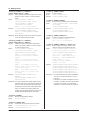
Metasyntax
The following table contains the symbols that are used in the syntax discussed mainly in chapters 4
and 5. These symbols are referred to as BNF (Backus-Naur Form) symbols. For details on how to
write data using these symbols, see pages 4-6 and 4-7.
Symbol
<>
{}
|
[]
iv
Description
A defined value
Select an option in { }
Exclusive OR
Can be omitted
Example
Example of Input
ELEMent<x> <x> = 1 to 6
ELEMENT2
SQFormula {TYPE1|TYPE2|TYPE3} SQFORMULA TYPE1
NUMeric[:NORMal]:VALue?
NUMERIC:VALUE?
IM WT1801-17EN
Contents
1
How to Use This Manual................................................................................................................... iii
Chapter 1 Ethernet Interface
1.1
1.2
1.3
1.4
Component Names and Functions.................................................................................... 1-1
Ethernet Interface Features and Specifications................................................................ 1-2
Connecting to the Ethernet Interface................................................................................. 1-3
Configuring the WT1800 Ethernet Settings....................................................................... 1-4
Chapter 2 USB Interface
2.1
2.2
2.3
2.4
Component Names and Functions.................................................................................... 2-1
USB Interface Features and Specifications....................................................................... 2-2
Connecting to the USB Interface....................................................................................... 2-3
Configuring the WT1800 USB Settings............................................................................. 2-4
2
3
4
5
Chapter 3 GP-IB Interface
3.1
3.2
3.3
3.4
3.5
Component Names and Functions.................................................................................... 3-1
GP-IB Interface Features and Specifications.................................................................... 3-2
Connecting to the GP-IB Interface.................................................................................... 3-4
Configuring the WT1800 GP-IB Settings........................................................................... 3-6
Responses to Interface Messages.................................................................................... 3-7
6
App
Chapter 4 Programming Overview
4.1
4.2
4.3
4.4
4.5
Messages.......................................................................................................................... 4-1
Commands........................................................................................................................ 4-3
Responses........................................................................................................................ 4-5
Data................................................................................................................................... 4-6
Synchronization with the Controller................................................................................... 4-8
Chapter 5 Commands
5.1
5.2
5.3
5.4
5.5
5.6
5.7
5.8
5.9
5.10
5.11
5.12
5.13
5.14
5.15
5.16
5.17
5.18
5.19
5.20
IM WT1801-17EN
List of Commands............................................................................................................. 5-1
AOUTput Group.............................................................................................................. 5-15
AUX Group...................................................................................................................... 5-16
COMMunicate Group...................................................................................................... 5-18
CURSor Group................................................................................................................ 5-20
DISPlay Group................................................................................................................ 5-22
FILE Group...................................................................................................................... 5-41
HARMonics Group.......................................................................................................... 5-44
HCOPy Group................................................................................................................. 5-45
HOLD Group................................................................................................................... 5-47
IMAGe Group.................................................................................................................. 5-48
INPut Group.................................................................................................................... 5-50
INTEGrate Group............................................................................................................ 5-60
MEASure Group.............................................................................................................. 5-63
MOTor Group................................................................................................................... 5-68
NUMeric Group............................................................................................................... 5-73
RATE Group.................................................................................................................... 5-83
STATus Group................................................................................................................. 5-84
STORe Group................................................................................................................. 5-85
SYSTem Group............................................................................................................... 5-88
Index
Contents
5.21
5.22
WAVeform Group............................................................................................................. 5-91
Common Command Group............................................................................................. 5-93
Chapter 6 Status Reports
6.1
6.2
6.3
6.4
6.5
Appendix
About Status Reports........................................................................................................ 6-1
Status Byte........................................................................................................................ 6-3
Standard Event Register................................................................................................... 6-4
Extended Event Register................................................................................................... 6-5
Output and Error Queues.................................................................................................. 6-6
Appendix 1
Appendix 2
Error Messages................................................................................................... App-1
About the IEEE 488.2-1992 Standard................................................................. App-4
Index
vi
IM WT1801-17EN
Chapter 1
1.1
Ethernet Interface
Component Names and Functions
Ethernet Interface
Front Panel
1
2
LOCAL key
Press this key to switch from remote mode,
in which settings and operations are
performed through remote commands,
to local mode, in which operations can be
performed using the WT1800 keys. This key
is disabled when local lockout (see page 1-2)
has been activated by a controller.
3
4
5
6
App
UTILITY key (page 1-5)
Press this key to set the network connection
timeout setting.
Index
Rear Panel
Ethernet port
This port is for connecting the WT1800
to a controller (such as a PC) using an
Ethernet cable. For details on how to
connect the WT1800 to a controller,
see page 1-4.
IM WT1801-17EN
1-1
1.2
Ethernet Interface Features and Specifications
Ethernet Interface Features
Reception Feature
You can use the reception feature to specify the same settings that you can specify by using the
front panel keys.
The WT1800 can receive output requests for measured and computed data, panel setup
parameters, and error codes.
Transmission Feature
The WT1800 can transmit measured and computed data.
The WT1800 can transmit panel setup parameters and the status byte.
The WT1800 can transmit error codes when errors occur.
Ethernet Interface Specifications
Electrical and mechanical specifications:
Simultaneous connections:
Communication protocol:
Connector:
complies with IEEE802.3
1
TCP/IP (VXI-11)
RJ-45
Switching between Remote and Local Modes
Switching from Local to Remote Mode
The WT1800 switches to remote mode when it is in local mode and it receives a :COMMunicate:
REMote ON command from the PC.
• The REMOTE indicator illuminates.
• All keys except the LOCAL key are disabled.
• The local mode settings are retained even when the WT1800 switches to remote mode.
Switching from Remote to Local Mode
When the WT1800 is in remote mode and you press LOCAL, the WT1800 switches to local
mode. However, this does not work if the WT1800 has received a :COMMunicate:LOCKout ON
command from the PC. The WT1800 switches to local mode when it receives a :COMMunicate:
REMote OFF command from the PC, regardless of the local lockout state.
• The REMOTE indicator turns off.
• Key operations are enabled.
• Settings entered in remote mode are retained even when the WT1800 switches to local mode.
Note
You cannot use the Ethernet interface simultaneously with other interfaces (GP-IB and USB interfaces).
Setting the Timeout Value
If the WT1800 is not accessed within a given period of time (specified by the timeout
value), it will disconnect from the network. The timeout value can be set from 0 to 3600 s.
The default value is 0 s.
For instructions on how to set the timeout value, see section 1.4, “Configuring the
WT1800 Ethernet Settings.”
1-2
IM WT1801-17EN
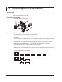
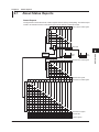
1.3
Connecting to the Ethernet Interface
1
Connect a UTP (Unshielded Twisted-Pair) or STP (Shielded Twisted-Pair) cable that is connected to
a hub or other network device to the Ethernet port on the WT1800 rear panel.
Ethernet Interface
Connection Procedure
2
3
Hub or router that supports 1000BASE-T/100BASE-TX
Controller
(PC or work station)
4
WT1800
5
UTP or STP cable
(straight cable)
6
Network card
App
Index
Ethernet port
RJ-45 modular jack
Notes about Connections
• To connect the WT1800 to a PC, be sure to use straight cables and to connect through a hub or
router. Proper operation is not guaranteed for a one-to-one connection using a crossover cable.
• Use a network cable that supports the data rate of your network.
Note
For details on how to connect the WT1800 to a network, see section 19.1, “Connecting the WT1800 to a
Network” in the WT1800 User’s Manual, IM WT1801-02EN.
IM WT1801-17EN
1-3
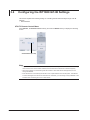
1.4
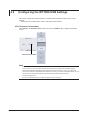
Configuring the WT1800 Ethernet Settings
This section explains the following setting for remotely controlling the WT1800 via the Ethernet
interface:
• Network connection timeout setting
UTILITY Remote Control Menu
Press UTILITY, the Remote Control soft key, and then the Network soft key to display the
following screen.
Set the timeout
with the cursor keys.
Note
Only use one communication interface: GP-IB, USB, or Network. If you send commands simultaneously from
more than one communication interface, the WT1800 will not execute the commands properly.
TCP/IP Settings
To use the Ethernet interface, you must specify the following TCP/IP settings.
• IP address
• Subnet mask
• Default gateway
For instructions on how to specify these settings, see section 19.2, “Configuring TCP/IP Settings” in
the WT1800 User’s Manual, IM WT1801-02EN.
1-4
IM WT1801-17EN
Chapter 2
2.1
USB Interface
Component Names and Functions
Front Panel
1
2
USB Interface
LOCAL key
Press this key to switch from remote mode,
in which settings and operations are
performed through remote commands, to
local mode, in which operations can be
performed using the WT1800 keys. This key
is disabled when local lockout (see page 2-2)
has been activated by a controller.
3
4
5
6
App
UTILITY key (page 2-4)
Press this key to view the serial number
that is used in USB TMC communication.
Index
Rear Panel
USB port
This port is for connecting the WT1800
to a controller (such as a PC) using a
USB cable. For details on how to
connect the WT1800 to a controller,
see page 2-3.
IM WT1801-17EN
2-1
2.2
USB Interface Features and Specifications
USB Interface Features
Reception Feature
You can use the reception feature to specify the same settings that you specify by using the front
panel keys.
The WT1800 can receive output requests for measured and computed data, panel setup
parameters, and error codes.
Transmission Feature
The WT1800 can transmit measured and computed data.
The WT1800 can transmit panel setup parameters and the status byte.
The WT1800 can transmit error codes when errors occur.
USB Interface Specifications
Electrical and mechanical specifications: complies with USB Rev. 2.0
Connector: type B connector (receptacle)
Number of ports: 1
Power supply: self-powered
System requirements:a PC with a USB port, running Windows 7 (32 bit), Windows Vista (32 bit),
or Windows XP (32 bit, SP2 or later). A separate device driver is required
to enable the connection with the PC.
Switching between Remote and Local Modes
Switching from Local to Remote Mode
The WT1800 switches to remote mode when it is in local mode and it receives a :COMMunicate:
REMote ON command from the PC.
• The REMOTE indicator illuminates.
• All keys except the LOCAL key are disabled.
• The local mode settings are retained even when the WT1800 switches to remote mode.
Switching from Remote to Local Mode
When the WT1800 is in remote mode and you press LOCAL, the WT1800 switches to local
mode. However, this does not work if the WT1800 has received a :COMMunicate:LOCKout ON
command from the PC. The WT1800 switches to local mode when it receives a :COMMunicate:
REMote OFF command from the PC, regardless of the local lockout state.
• The REMOTE indicator turns off.
• Key operations are enabled.
• Settings entered in remote mode are retained even when the WT1800 switches to local mode.
Note
You cannot use the USB interface simultaneously with other interfaces (GP-IB and Ethernet interfaces).
2-2
IM WT1801-17EN
2.3
Connecting to the USB Interface
1
Notes about Connections
2
USB Interface
• Be sure to insert the USB cable connector firmly into the USB port.
• If you are connecting multiple devices by using a USB hub, connect the WT1800 to the USB hub
port that is closest to the port that the controller is connected to.
• Do not connect or remove USB cables from the time when the WT1800 is turned on until
operation becomes available (approximately 20 to 30 seconds). Doing so may damage the
WT1800.
3
4
5
6
App
Index
IM WT1801-17EN
2-3
2.4
Configuring the WT1800 USB Settings
This section explains the following setting for controlling the WT1800 remotely through a USB
interface:
• Viewing the serial number that is used in USB TMC communications
UTILITY Remote Control Menu
Press UTILITY, the Remote Control soft key, and then the USB soft key to display the following
screen.
Check the serial number.
Note
• Only use one communication interface: GP-IB, USB, or Network. If you send commands simultaneously
from more than one communication interface, the WT1800 will not execute the commands properly.
• Install the YOKOGAWA USB TMC (Test and Measurement Class) driver on your PC. For information
about how to obtain the YOKOGAWA USB TMC driver, contact your nearest YOKOGAWA dealer. You can
also access the YOKOGAWA USB driver download web page and download the driver.
http://tmi.yokogawa.com/
• Do not use USB TMC drivers (or software) supplied by other companies.
2-4
IM WT1801-17EN
Chapter 3
3.1
GP-IB Interface
Component Names and Functions
Front Panel
1
2
LOCAL key
Press this key to switch from remote mode,
in which settings and operations are
performed through remote commands, to
local mode, in which operations can be
performed using the WT1800 keys. This key
is disabled when local lockout (see page 3-7)
has been activated by a controller.
3
GP-IB Interface
4
5
6
App
UTILITY key (page 3-6)
Press this key to set the GP-IB address.
Index
Rear Panel
GP-IB port
This port is for connecting the WT1800
to a controller (such as a PC) using a
GP-IB cable. For details on how to
connect the WT1800 to a controller,
see page 3-4.
IM WT1801-17EN
3-1
3.2
GP-IB Interface Features and Specifications
GP-IB Interface Features
Listener Capability
• Allows you to specify the same settings that you can specify by using the front panel keys. This
does not allow you to turn the power on and off or change communication settings.
• Output requests for measured and computed data, panel setup parameters, and error codes can
be received.
• Commands such as status report commands can be received.
Talker Capability
The WT1800 can transmit measured and computed data.
The WT1800 can transmit panel setup parameters and the status byte.
The WT1800 can transmit error codes when errors occur.
Note
Talk-only, listen-only, and controller capabilities are not available on the WT1800.
GP-IB Interface Specifications
Supported Devices: National Instruments Corporation
• PCI-GPIB or PCI-GPIB+
• PCIe-GPIB or PCIe-GPIB+
•PCMCIA-GPIB or PCMCIA-GPIB+
• GPIB-USB-HS
Driver NI-488.2M Version 1.60 or later
Electrical and mechanical specifications: complies with IEEE St’d 488-1978
Functional specifications:
See the following table.
Protocol:
complies with IEEE St’d 488.2-1992
Code:
ISO (ASCII) code
Mode:
addressable mode
Address settings:Press UTILITY, and then on the Remote Control menu, set the
communication interface (Device) to GP-IB and the address to a
number from 0 to 30.
Clearing remote mode: Clear remote mode by pressing LOCAL.
This key is disabled when local lockout has been activated by a
controller.
Functional Specifications
3-2
Function
Source handshaking
Acceptor handshaking
Talker
Subset Name
SH1
AH1
T6
Listener
L4
Service request
Remote local
Parallel polling
Device clear
Device trigger
Controller
Electric characteristics
SR1
RL1
PP0
DC1
DT1
C0
E1
Description
Full source handshaking capability
Full acceptor handshaking capability
Basic talker capability, serial polling, and untalk on MLA (My
Listen Address). No talk-only capability.
Basic listener capability, unlisten on MTA (My Talk Address),
and no listen-only capability
Full service request capability
Full remote/local capability
No parallel poll capability
Full device clear capability
Device trigger capability
No controller capability
Open collector
IM WT1801-17EN
3.2 GP-IB Interface Features and Specifications
1
Switching between Remote and Local Modes
Switching from Local to Remote Mode
The WT1800 switches to remote mode when it is in local mode and it receives a REN (Remote
Enable) message from the PC.
• The REMOTE indicator illuminates.
• All keys except the LOCAL key are disabled.
• The local mode settings are retained even when the WT1800 switches to remote mode.
2
3
When the WT1800 is in remote mode and you press LOCAL, the WT1800 switches to local mode.
This key combination is disabled if the local lockout state (see page 3-7 for details) has been
activated by a controller.
• The REMOTE indicator turns off.
• Key operations are enabled.
• Settings entered in remote mode are retained even when the WT1800 switches to local mode.
GP-IB Interface
Switching from Remote to Local Mode
4
5
Note
You cannot use the GP-IB interface simultaneously with other interfaces (USB and Ethernet interfaces).
6
App
Index
IM WT1801-17EN
3-3
3.3
Connecting to the GP-IB Interface
GP-IB Cable
The WT1800 is equipped with an IEEE St’d 488-1978 24-pin GP-IB connector. Use GP-IB cables
that comply with IEEE St’d 488-1978.
Connection Procedure
Connect the cable as shown below.
Notes about Connections
• Firmly tighten the screws on the GP-IB cable connector.
• On the PC end, use a GP-IB board (or card) made by National Instruments. For details, see
section 3.2.
• The WT1800 may not operate properly if the WT1800 is connected to the PC through converters
(such as a GP-IB to USB converter). For more details, contact your nearest YOKOGAWA dealer.
• Several cables can be used to connect multiple devices. However, no more than 15 devices,
including the controller, can be connected on a single bus.
• When connecting multiple devices, you must assign a unique address to each device.
• Use cables that are 2 m or shorter in length to connect devices.
• Make sure the total length of all cables does not exceed 20 m.
• When devices are communicating, have at least two-thirds of the devices on the bus turned on.
• To connect multiple devices, use a star or daisy-chain configuration as shown below. Loop and
parallel configurations are not allowed.
3-4
IM WT1801-17EN
3.3 Connecting to the GP-IB Interface
1
CAUTION
Be sure to turn off the PC and the WT1800 when connecting or removing communication
cables. Otherwise, erroneous operation may result, or the internal circuitry may break.
2
3
GP-IB Interface
4
5
6
App
Index
IM WT1801-17EN
3-5
3.4
Configuring the WT1800 GP-IB Settings
This section explains the following setting for controlling the WT1800 remotely through a GP-IB
interface:
• GP-IB address
UTILITY Remote Control Menu
Press UTILITY, the Remote Control soft key, and then the GP-IB soft key to display the following
screen.
Set the address (0 to 30).
Note
• Only use one communication interface: GP-IB, USB, or Network. If you send commands simultaneously
from more than one communication interface, the WT1800 will not execute the commands properly.
• When the controller is communicating with the WT1800 or with other devices through GP-IB, do not
change the address.
• Each device that is connected by GP-IB has its own unique address in the GP-IB system. This address
is used to distinguish one device from other devices. Therefore, you must assign a unique address to the
WT1800 when connecting it to a PC or other device.
3-6
IM WT1801-17EN
3.5
Responses to Interface Messages
1
2
Responses to Interface Messages
Responses to Uni-Line Messages
• IFC (Interface Clear)
3
Clears the talker and listener functions. Stops data transmission if it is in progress.
GP-IB Interface
• REN (Remote Enable)
Switches between the remote and local modes.
4
IDY (Identify) is not supported.
Responses to Multi-Line Messages (Address commands)
5
• GTL (Go To Local)
Switches the instrument to local mode.
• SDC (Selected Device Clear)
• Clears the program message (command) being received and the output queue (see page 6-6
for details).
• Discards *OPC and *OPC? commands that are being executed.
• Immediately aborts *WAI and COMMunicate:WAIT commands.
• GET (Group Execute Trigger)
6
App
The same operation as the *TRG command.
PPC (Parallel Poll Configure) and TCT (Take Control) are not supported.
Index
Responses to Multi-Line Messages (Universal commands)
• LLO (Local Lockout)
Prohibits switching to local mode by disabling the LOCAL key on the front panel.
• DCL (Device Clear)
The same operation as the SDC message.
• SPE (Serial Poll Enable)
Sets the talker function on all devices on the bus to serial polling mode. The controller will poll
each device in order.
• SPD (Serial Poll Disable)
Clears the serial polling mode of the talker function on all devices on the bus.
PPU (Parallel Poll Unconfigure) is not supported.
What Are Interface Messages?
Interface messages are also referred to as interface commands or bus commands. They are
commands that are issued by the controller. They are classified as follows:
Uni-Line Messages
A single control line is used to transmit uni-line messages. The following three messages are
available.
• IFC (Interface Clear)
• REN (Remote Enable)
• IDY (Identify)
IM WT1801-17EN
3-7
3.5 Responses to Interface Messages
Multi-Line Messages
Eight data lines are used to transmit multi-line messages. The messages are classified as follows:
• Address Commands
These commands are valid when the instrument is designated as a listener or as a talker. The
following five commands are available.
Commands available to a device designated as a listener
• GTL (Go To Local)
• SDC (Selected Device Clear)
• PPC (Parallel Poll Configure)
• GET (Group Execute Trigger)
Commands available to a device designated as a talker
• TCT (Take Control)
• Universal Commands
These commands are valid on all instruments regardless of their listener or talker designation.
The following five commands are available.
• LLO (Local Lockout)
• DCL (Device Clear)
• PPU (Parallel Poll Unconfigure)
• SPE (Serial Poll Enable)
• SPD (Serial Poll Disable)
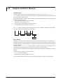
There are other interface messages: listener-address, talk-address, and secondary commands.
Uni-line
messages
IFC
REN
IDY
Listener
address
Interface messages
Multi-line messages
Address
commands
Universal
commands
GTL
SDC
PPC
GET
TCT
LLO
DCL
PPU
SPE
SPD
Talker
address
Secondary
commands
The WT1800 supports interface messages marked with a «.
Note
Difference between SDC and DCL
In multi-line messages, SDC messages are address commands that require talker or listener designation and
DCL messages are universal commands that do not require a designation. Therefore, SDC messages are
directed at a particular instrument while DCL messages are directed at all instruments on the bus.
3-8
IM WT1801-17EN
Chapter 4
Programming Overview
4.1
Messages
1
Messages
Program Messages
The program message format is shown below.
;
<Program message unit>
<PMT>
<Program Message Unit>
A program message consists of one or more program
message units. Each unit corresponds to one
command. The WT1800 executes the commands in
the order that they are received.
Separate each program message unit with a
semicolon.
For details on the program message syntax, see the
next section.
Example
:INPut:CFACtor 3;INDependent OFF<PMT>
Unit
Unit
<PMT>
<PMT> is a program message terminator. The
following three terminators are available.
NL (new line): Same as LF (line feed). ASCII code
“0AH”
^END:
The END message as defined by IEEE
488.1.
(The data byte that is sent with the
END message is the last data byte of
the program message.)
NL^END:
NL with an END message attached.
(NL is not included in the program
message.)
IM WT1801-17EN
Program Message Unit Syntax
2
The program message unit syntax is shown below.
,
<Program header>
Space
<Program data>
3
<Program Header>
The program header indicates the command type. For
details, see page 4-3.
<Program Data>
Attach program data if there are conditions that are
required to execute a command. Separate the program
data from the header with a space (ASCII code “20H”).
If there are multiple data values, separate each data
value with a comma.
For details, see page 4-6.
Example
:INPut:CFACtor 3<PMT>
Header
Data
Response Messages
;
<RMT>
<Response Message Unit>
A response message consists of one or more
response message units; each response message unit
corresponds to one response.
Separate each response message unit with a
semicolon.
For details on the response message syntax, see the
next page.
Example
:INPUT:CFACTOR 3;INDEPENDENT 0<RMT>
Unit
5
6
App
Index
The response message syntax is as follows:
<Response message unit>
4
Programming Overview
Messages are used to exchange information between
the controller and the WT1800. Messages that are
sent from the controller to the WT1800 are called
program messages, and messages that are sent from
the WT1800 back to the controller are called response
messages.
If a program message contains a command that
requests a response (query), the WT1800 returns
a response message upon receiving the program
message. The WT1800 returns a single response
message in response to a single program message.
Unit
<RMT>
RMT stands for “response message terminator.” The
response message terminator is NL^END.
4-1
4.1 Messages
Response Message Unit Syntax
The response message unit syntax is as follows:
,
<Response header>
Space
<Response data>
<Response Header>
A response header sometimes precedes the response
data. Separate the data from the header with a space.
For details, see page 4-5.
<Response Data>
Response data contains the content of the response.
If there are multiple data values, each data value is
separated by a comma. For details, see page 4-5.
Example
100.00E-03<RMT> :DISPLAY:MODE WAVE<RMT>
Data
Header
Data
If there are multiple queries in a program message,
responses are returned in the same order that the
queries were received in. In most cases, a single query
returns a single response message unit, but there
are a few queries that return multiple units. The first
response message unit always corresponds to the first
query, but the nth response unit may not necessarily
correspond to the nth query. Therefore, if you want to
make sure that every response is retrieved, divide the
program messages into individual messages.
• If the controller sends a program message
containing multiple message units, but the message
contains incomplete units, the WT1800 will try to
execute the ones that are believed to be complete.
However, these attempts may not always be
successful. In addition, if such a message contains
queries, the WT1800 may not necessary return
responses.
Deadlock
The WT1800 can store at least 1024 bytes of
messages in its transmit and receive buffers (the
number of available bytes varies depending on the
operating conditions). If both the transmit and receive
buffers become full at the same time, the WT1800 will
no longer be able to operate. This condition is called a
deadlock. If this happens, you can resume operation
by discarding response messages.
Deadlock will not occur if the program message
(including the <PMT>) is kept below 1024 bytes.
Program messages that do not contain queries never
cause deadlocks.
Precautions to Be Taken when Sending and
Receiving Messages
• If the controller sends a program message that does
not contain a query, the controller can send the next
program message at any time.
• If the controller sends a program message that
contains a query, the controller must finish receiving
the response message before it can send the next
program message. If the controller sends the next
program message before receiving the response
message in its entirety, an error will occur. A
response message that is not received in its entirety
will be discarded.
• If the controller tries to receive a response message
when there is none, an error will occur. If the
controller tries to receive a response message
before the transmission of the program message is
complete, an error will occur.
4-2
IM WT1801-17EN
4.2
Commands
Commands
There are three types of commands (program headers)
that a controller may send to the WT1800. The
commands differ in their program header formats.
Common Command Header
?
<Mnemonic>
*
Common command example: *CLS
Compound Header
Commands, other than common commands, that are
specific to the WT1800 are classified and arranged in
a hierarchy according to their functions. The compound
header syntax is shown below. Be sure to use a colon
to specify a lower hierarchical level.
:
:
?
<Mnemonic>
Compound header example: :DISPlay:MODE
Simple Header
These commands are functionally independent and are
not contained within a hierarchy. The format of a simple
header is shown below.
:
<Mnemonic>
?
Simple header example: :HOLD
Note
A <mnemonic> is an alphanumeric character string.
When Concatenating Commands
• Command Groups
A command group is a group of commands that
have common compound headers arranged in a
hierarchy. A command group may contain subgroups.
IM WT1801-17EN
2
Example A portion of the commands from the
integration command group
:INTEGrate?
:INTEGrate:MODE
:INTEGrate:TIMer
:INTEGrate:RTIMe?
:INTEGrate:RTIMe:STARt
:INTEGrate:RTIMe:END
:INTEGrate:ACAL
:INTEGrate:STARt
:INTEGrate:STOP
:INTEGrate:RESet
3
4
Programming Overview
Commands that are defined in IEEE 488.2-1992 are
called common commands. The common command
header syntax is shown below. Be sure to include an
asterisk (*) at the beginning of a common command.
1
5
• When Concatenating Commands of the Same
Group
The WT1800 stores the hierarchical level of the
command that is currently being executed and
processes the next command on the assumption
that it belongs to the same level. Therefore,
the common header section can be omitted for
commands that belong to the same group.
Example :INTEGrate:MODE NORMal;
ACAL ON<PMT>
6
App
• When Concatenating Commands of Different
Groups
If the subsequent command does not belong to the
same group, place a colon in front of the header (this
colon cannot be omitted).
Example :INTEGrate:MODE NORMal;:
DISPlay:MODE NUMeric<PMT>
• When Concatenating Simple Headers
If a simple header follows another command, place
a colon in front of the simple header (this colon
cannot be omitted).
Example :INTEGrate:MODE NORMal;:
HOLD ON<PMT>
• When Concatenating Common Commands
Common commands that are defined in IEEE
488.2-1992 are independent of hierarchy. There is
no need to use a colon.
Example :INTEGrate:MODE NORMal;*CLS;
ACAL ON<PMT>
• When Separating Commands with <PMT>
If you separate two commands with a terminator,
two program messages will be sent. Therefore,
the common header must be specified for each
command even when commands belonging to the
same command group are being concatenated.
Example :INTEGrate:MODE NORMal<PMT>:
INTEGrate:ACAL ON<PMT>
4-3
Index
4.2 Commands
Upper-Level Query
An upper-level query is a query that is made by
appending a question mark to the highest level
command of a group. The controller can receive all
of the settings in a group collectively by executing
an upper-level query. Some upper-level queries of a
group, which may be comprised of more than three
hierarchical levels, can cause the WT1800 to transmit
all the lower level settings.
INTEGrate?<PMT> -> :INTEGRATE:
Example:
MODE NORMAL;TIMER 0,0,0;
ACAL 0<RMT>
The response to an upper-level query can be sent
back to the WT1800 as a program message. This
enables the settings that were present when the upperlevel query was made to be reproduced later on.
However, some upper-level queries do not return setup
parameters that are not currently in use. Exercise
caution because not all of a group’s information is
necessarily returned in a response.
Header Interpretation Rules
The WT1800 interprets the header that it receives
according to the rules below.
• Mnemonics are not case sensitive.
Example"CURSor" can be written as "cursor"
or "Cursor."
• The lower-case characters can be omitted.
Example"CURSor" can be written as "CURSO"
or "CURS."
• The question mark at the end of a header indicates
that it is a query. You cannot omit the question mark.
ExampleThe shortest abbreviation for
"CURSor?" is "CURS?."
• If the <x> (value) at the end of a mnemonic is
omitted, it is interpreted as a 1.
ExampleIf "ELEMent<x>" is written as "ELEM,"
it means "ELEMent1."
• Parts of commands and parameters enclosed in
square brackets ([ ]) can be omitted.
Example"[:INPut]SCALing[:STATe][:ALL]
ON" can be written as "SCAL
ON."
However, the last section enclosed in square
brackets cannot be omitted in an upper-level query.
Example: "SCALing?" and "SCALing:STATe?"
are different queries.
4-4
IM WT1801-17EN
4.3
Responses
1
Responses
2
When the controller sends a query (a command with
a question mark), the WT1800 returns a response
message to the query. The WT1800 returns response
messages in one of the following two forms.
3
• Response Consisting of a Header and Data
Responses that can be used as program messages
without any changes are returned with command
headers attached.
Example :DISPlay:MODE?<PMT> -> :
DISPLAY:MODE WAVE<RMT>
4
Programming Overview
5
• Response Consisting Only of Data
Responses that cannot be used as program
messages unless changes are made (query-only
commands) are returned without headers. However,
there are query-only commands whose responses
the WT1800 will attach headers to.
Example [:INPut]:POVer?<PMT> -> 0<RMT>
6
App
If You Want the WT1800 to Return Responses
without Headers
You can configure the WT1800 so that even responses
that have both headers and data are returned without
headers. Use the COMMunicate:HEADer command
for this purpose.
Index
Abbreviated Form
The WT1800 normally returns response headers with
the lower-case section removed. You can configure
the WT1800 so that full headers are returned. Use the
COMMunicate:VERBose command for this purpose.
The sections enclosed in square brackets ([ ]) are also
omitted in the abbreviated form.
IM WT1801-17EN
4-5
4.4
Data
Data
Data contains conditions and values that are written
after the header. A space separates the data from the
header. Data is classified as follows:
Data
<Decimal>
Meaning
A value expressed in decimal notation
(Example: VT ratio setting
->[:INPut]:SCALing:VT:
ELEMent1 100)
<Voltage><Current> A physical value
<Time><Frequency> (Example: Voltage range setting
->[:INPut]:VOLTage:RANGE:
ELEMent1 100V)
A register value expressed as binary, octal,
<Register>
decimal, or hexadecimal
(Example: Extended event register value
->:STATUS:EESE #HFE)
<Character data>
Predefined character string (mnemonic).
Select from the available strings in braces.
(Example: Trigger mode selection
->:DISPlay:WAVE:TRIGger:
MODE {AUTO|NORMal|OFF})
Indicates on and off. Specify ON, OFF, or a
<Boolean>
value.
(Example: Turning data hold on
->:HOLD ON)
<String data>
User-defined string
(Example: User-defined function
->:MEASure:FUNCtion1:
EXPRession "URMS(E1)")
Indicates a file name.
<Filename>
(Example: Save file name
->:FILE:SAVE:
SETup[:EXECute] "CASE1")
Data that contains 8-bit values
<Block data>
(Example: Response to acquired waveform
data
-> #40012ABCDEFGHIJKL)
<Decimal>
<Decimal> indicates a value expressed as a decimal
number, as shown in the table below. Decimal values
are written in the NR form as specified in ANSI
X3.42-1975.
Symbol
<NR1>
<NR2>
<NR3>
<NRf>
Meaning
Example
125
-1
Integer
-.90
Fixed-point number 125.0
Floating-point number 125.0E+0 -9E-1
Any form from <NR1> to <NR3>
+1000
+001.
+.1E4
• The WT1800 can receive decimal values that are
sent from the controller in any form, from <NR1> to
<NR3>. This is expressed as <NRf>.
• The WT1800 returns a response to the controller in
one of the forms from <NR1> to <NR3> depending
on the query. The same form is used regardless of
the size of the value.
• For the <NR3> form, the plus sign after the “E” can
be omitted. You cannot omit the minus sign.
4-6
• If a value outside the range is entered, the value is
adjusted to the closest value within the range.
• If a value has more significant digits than are
available, the value will be rounded.
<Voltage>, <Current>, <Time>, and <Frequency>
<Voltage>, <Current>, <Time>, and <Frequency>
indicate decimal values that have physical significance.
A <Multiplier> or <Unit> can be attached to the <NRf>
form that was described earlier. The following types of
expressions are possible.
Form
<NRf><Multiplier><Unit>
<NRf><Unit>
<NRf><Multiplier> <NRf>
Example
5MV
5E-3V
5M
5E-3
<Multiplier>
<Multipliers> that you can use are indicated in the
following table.
Symbol
EX
PE
T
G
MA
K
M
U
N
P
F
Word
Exa
Peta
Tera
Giga
Mega
Kilo
Milli
Micro
Nano
Pico
Femto
Multiplier
1018
1015
1012
109
106
103
10–3
10–6
10–9
10–12
10–15
<Unit>
<Units> that you can use are indicated in the following
table.
Symbol
V
A
S
HZ
MHZ
Word
Volt
Ampere
Second
Hertz
Megahertz
Meaning
Voltage
Current
Time
Frequency
Frequency
• <Multiplier> and <Unit> are not case sensitive.
• “U” is used to indicate micro (“μ”).
• “MA” is used for Mega to distinguish it from Milli.
However, “MA” is interpreted as milliampere for
current. In addition, megahertz is expressed as
“MHZ.” Therefore, “M (Milli)” cannot be used for
frequencies.
• If both <Multiplier> and <Unit> are omitted, the basic
unit (V, A, S, or HZ) is used.
• Response messages are always expressed in the
<NR3> form. Additionally, they are returned using
the basic units, without a multiplier or unit attached.
IM WT1801-17EN
4.4 Data
Form
<NRf>
#H<Hexadecimal value made up of the digits 0 to 9 and A to F>
#Q<Octal value made up of the digits 0 to 7>
#B<Binary value made up of the digits 0 and 1>
Example
1
#H0F
#Q777
#B001100
• <Register> is not case sensitive.
• Response messages are always expressed in the
<NR1> form.
<Character Data>
<Character data> is a predefined character string (a
mnemonic). It is mainly used to indicate that an option
listed as a character string in braces must be selected
and entered. The data interpretation rules are the same
as those described in “Header Interpretation Rules” on
page 4-4.
Form
{AUTO|NORMal}
Example
AUTO
• As with the header, the COMMunicate:VERBose
command can be used to select whether to return
the response in the full form or in the abbreviated
form.
• The COMMunicate:HEADer setting does not affect
<character data>.
<Boolean>
<Boolean> is data that indicates ON or OFF. The
following types of expressions are possible.
Form
{ON|OFF|<NRf>}
• If a character string contains a double quotation
mark ("), the double quotation mark is expressed as
two consecutive quotation marks (""). This rule also
applies to single quotation marks.
• A response message is always enclosed in double
quotation marks (").
• <String data> is any character string. Therefore, the
instrument assumes that the remaining program
message units are part of the character string if no
closing single (') or double quotation mark (") is
encountered. As a result, no error is detected if a
quotation mark is omitted.
1
<Block Data>
<Block data> is any 8-bit data. It is only used in
response messages on the WT1800. The syntax is as
follows:
Programming Overview
<Register>
<Register> is an integer that can be expressed in
decimal, hexadecimal, octal, or binary notation. It is used
when each bit of the value has a particular meaning.
The following types of expressions are possible.
Form
Example
#N<N-digit decimal number><data byte sequence>#800000010ABCDEFGHIJ
• #N
Indicates that the data is <block data>. “N” indicates
the number of succeeding data bytes (digits) in
ASCII code.
• <N-digit decimal number>
Indicates the number of bytes of data (example:
00000010 = 10 bytes).
• <Data byte sequence>
Expresses the actual data (example: ABCDEFGHIJ).
• Data is comprised of 8-bit values (0 to 255). This
means that the ASCII code “0AH,” which stands for
“NL,” can also be included in the data. Hence, care
must be taken when programming the controller.
Example
ON OFF 1 0
• When <Boolean> is expressed in the <NRf> form,
“OFF” is selected if the rounded integer value is 0,
and “ON” is selected for all other cases.
• A response message is always returned with a 1 if
the value is ON and with a 0 if the value is OFF.
<String Data>
<String data> is not a predefined character string like
<character data>. It can be any character string. The
character string must be enclosed in single quotation
marks (') or double quotation marks (").
Form
<String data>
IM WT1801-17EN
Example
'ABC' "IEEE488.2-1992"
4-7
2
3
4
5
6
App
Index
4.5
Synchronization with the Controller
Overlap Commands and Sequential Commands
There are two types of commands: overlap and
sequential. The execution of one overlap command
can start before the execution of the previous overlap
command is completed.
If you specify the voltage range and send the next
program message while you are querying the result,
the WT1800 always returns the most recent setting (100
V in this case).
:INPut:VOLTage:RANGe;ELEMent1 100V;
ELEMent?<PMT>
This is because the next command is forced to
wait until the processing of :INPut:VOLTage:
RANGe;ELEMent1 is completed. This type of
command is called a sequential command.
Let us assume you send the next program message
when you want to load a file and query the voltage
range of the result.
:FILE:LOAD:SETup “ FILE1";:INPut:VOLTage:
RANGe:ELEMent1?
In this case, :INPut:VOLTage:RANGe:ELEMent1?
is executed before the loading of the file is completed,
and the voltage range that is returned is the value
before the file is loaded.
Overlapping refers to the act of executing the next
command before the processing of the current
command is completed, such as in the command
FILE:LOAD:SETup. A command that operates in this
way is called an overlap command.
You can prevent overlapping by using the following
methods.
Synchronizing to Overlap Commands
• Using the *WAI command
The *WAI command holds the subsequent
commands until the overlap command is completed.
Example :COMMunicate:OPSE #H0040;:
FILE:LOAD:SETup "FILE1";*WAI;:
INPut:VOLTage:RANGe:
ELEMent1?<PMT>
The COMMunicate:OPSE command is used to
select which command to apply *WAI to. Here, it is
applied to the media access command.
*WAI is executed before :INPut:VOLTage:
RANGe:ELEMent1?, so :INPut:VOLTage:
RANGe:ELEMent1? is not executed until the file
loading is completed.
4-8
• Using the COMMunicate:OVERlap command
The COMMunicate:OVERlap command enables (or
disables) overlapping.
Example :COMMunicate:OVERlap #HFFBF;:
FILE:LOAD:SETup "FILE1";:
INPut:VOLTage:RANGe:
ELEMent1?<PMT>
COMMunicate:OVERlap #HFFBF enables
overlapping for commands other than media access.
Because overlapping of file loading is disabled,
FILE:LOAD:SETup operates in the same way as
a sequential command. Thus, :INPut:VOLTage:
RANGe:ELEMent1? is not executed until file loading
is completed.
• Using the *OPC command
The *OPC command sets the OPC bit, which is bit
0 in the standard event register (see page 6-4 for
details), to 1 when the overlapping is completed.
Example :COMMunicate:OPSE #H0040;
*ESE 1;*ESR?;*SRE 32;:FILE:
LOAD:SETup "FILE1";*OPC<PMT>
(Read the response to*ESR?)
(Wait for a service request)
:INPut:VOLTage:RANGe:
ELEMent1?<PMT>
COMMunicate:OPSE
command is used to
The
select which command to apply *OPC to. Here, it is
applied to the media access command.
*ESE 1 and *SRE 32 indicate that a service
request is only generated when the OPC bit
becomes 1.
*ESR? clears the standard event register.
In the example above, :INPut:VOLTage:RANGe:
ELEMent1? is not executed until a service request
is generated.
• Using the *OPC? query
The *OPC? query generates a response when an
overlapping operation is completed.
Example :COMMunicate:OPSE #H0040;
:FILE:LOAD:SETup "FILE1";
*OPC?<PMT>
(Read the response to *OPC?)
:INPut:VOLTage:RANGe:
ELEMent?<PMT>
IM WT1801-17EN
4.5 Synchronization with the Controller
The COMMunicate:OPSE command is used to
select which command to apply *OPC? to. Here, it is
applied to the media access command.
Because *OPC? does not generate a response
until the overlapping operation is completed, the file
loading will have been completed by the time the
response to *OPC? is read.
Note
Most commands are sequential commands. Overlap
commands are indicated as such in chapter 5. All other
commands are sequential commands.
Even when using sequential commands, there are
times when it is necessary to achieve synchronization
to properly query the measured data. For example,
if you want to query the most recent numeric data
each time that the measured data is updated, you
can attempt to do this by sending the :NUMeric[:
NORMal]:VALue? command with some arbitrary
timing. However, because the WT1800 returns the
current measured data regardless of whether the
measured data has been updated since the previous
query, this method may return data that is the same
as the previous data. If this happens, you must use
the following method to synchronize with the end of
measured data updating.
• Using the STATus:CONDition? query
STATus:CONDition? is used to query the contents
of the condition register (see page 6-5 for details).
You can determine whether the measured data
is being updated by reading bit 0 of the condition
register. If bit 0 of the condition register is 1, the
measured data is being updated. If it is 0, the
measured data can be queried.
• Using the extended event register
The changes in the condition register can be
reflected in the extended event register (see page
6-5 for details).
Example :STATus:FILTer1 FALL;:STATus:
EESE 1;EESR?;*SRE 8<PMT>
(Read the response to STATus:EESR?)
Loop
IM WT1801-17EN
• Using the COMMunicate:WAIT command
The COMMunicate:WAIT command is used to wait
for a specific event to occur.
Example ::STATus:FILTer1 FALL;:STATus:
EESR?<PMT>
(Read the response to STATus:EESR?)
Loop
COMMunicate:WAIT 1<PMT>
:NUMeric[:NORMal]:VALue?<PMT>
(Read the response to
:NUMeric[]NORMal]:VALue?)
:STATus:EESR?<PMT>
(Read the response to STATus:EESR?)
(Return to Loop)
For a description of STATus:FILTer1 FALL and
STATus:EESR?, see the previous section about the
1
2
3
4
Programming Overview
Achieving Synchronization without Using
Overlap Commands
The STATus:FILTer1 FALL command sets the
transition filter so that bit 0 in the extended event
(FILTer1) is set to 1 when bit 0 in the condition
register changes from 1 to 0.
The STATus:EESE 1 command is used to only
change the status byte based on bit 0 in the
extended event register.
The STATus:EESR? command is used to clear the
extended event register.
The *SRE 8 command is used to generate service
requests based only on the changes in the extended
event register bits.
The :NUMeric[:NORMal]:VALue? command is
not executed until a service request is generated.
5
6
App
extended event register.
The COMMunicate:WAIT 1 command specifies
that the program will wait for bit 0 in the extended
event register to be set to 1.
:NUMeric[:NORMal]:VALue? is not executed
until bit 0 in the extended event register becomes 1.
(Wait for a service request)
:NUMeric[:NORMal]:VALue?<PMT>
(Read the response to
:NUMeric[]NORMal]:VALue?)
:STATus:EESR?<PMT>
(Read the response to STATus:EESR?)
(Return to Loop)
4-9
Index
Chapter 5
Commands
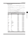
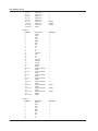
List of Commands
Command
AOUTput Group
:AOUTput?
:AOUTput:NORMal?
:AOUTput[:NORMal]:CHANnel<x>
:AOUTput[:NORMal]:IRTime
:AOUTput[:NORMal]:MODE<x>
:AOUTput[:NORMal]:RATE<x>
Function
Page
Queries all D/A output settings.
Queries all D/A output settings.
Sets or queries a D/A output item (function, element, or harmonic order).
Sets or queries the integration time that is used in the D/A output of the
integrated value.
Sets or queries the rated-value setup mode for D/A output items.
Sets or queries the rated maximum or minimum value for D/A output items.
5-15
5-15
5-15
5-15
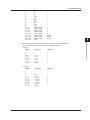
AUX Group
:AUX<x>?
:AUX<x>:AUTO
:COMMunicate?
:COMMunicate:HEADer
:COMMunicate:LOCKout
:COMMunicate:OPSE
:COMMunicate:OPSR?
:COMMunicate:OVERlap
:COMMunicate:REMote
:COMMunicate:VERBose
:COMMunicate:WAIT
:COMMunicate:WAIT?
CURSor Group
:CURSor?
:CURSor:BAR?
:CURSor:BAR:LINKage
:CURSor:BAR:POSition<x>
:CURSor:BAR[:STATe]
:CURSor:BAR:{Y<x>|DY}?
IM WT1801-17EN
Queries all communication settings.
Sets or queries whether a header is added to the response to a query.
(Example with header: “:DISPLAY:MODE NUMERIC.” Example without
header: “NUMERIC.”)
Sets or clears local lockout.
Sets or queries the overlap command that is used by the *OPC, *OPC?, and
*WAI commands.
Queries the operation pending status register.
Sets or queries the commands that operate as overlap commands.
Sets the WT1800 to remote or local mode. On is remote mode.
Sets or queries whether the response to a query is returned fully spelled
out (example: “:INPUT:VOLTAGE:RANGE:ELEMENT1 1.000E+03”) or in its
abbreviated form (example: “VOLT:RANG:ELEM 1.000E+03”).
Waits for a specified extended event to occur.
Creates the response that is returned when a specified extended event
occurs.
Queries all cursor measurement settings.
Queries all bar graph display cursor measurement settings.
Sets or queries the on/off status of the cursor position linkage on the bar
graph display.
Sets or queries the position of the specified cursor on the bar graph display.
Sets or queries the on/off status of the cursor display on the bar graph
display.
Queries the measured value of the specified cursor on the bar graph display.
5-15
5-15
5-16
5-16
5-16
5-16
5-16
5-16
5-16
5-16
5-16
5-17
5-17
5-17
5-17
5-17
5-18
5-18
5-18
5-18
5-18
5-18
5-19
5-19
5-19
5-19
5-20
5-20
5-20
5-20
5-20
5-20
5-1
2
3
4
5
Commands
Queries all auxiliary input settings.
Sets or queries the voltage auto range on/off status of the specified auxiliary
input.
:AUX<x>:FILTer?
Queries all input filter settings for the auxiliary inputs.
:AUX<x>:FILTer[:LINE]
Sets or queries the line filter for the auxiliary inputs.
:AUX<x>:LSCale?
Queries all auxiliary input linear scaling settings.
:AUX<x>:LSCale:AVALue
Sets or queries the slope (A) of the linear scale of the auxiliary input feature.
:AUX<x>:LSCale:BVALue
Sets or queries the offset (B) of the linear scale of the auxiliary input feature.
:AUX<x>:LSCale:CALCulate?
Queries all parameter calculation settings for the linear scale of the auxiliary
input feature.
:AUX<x>:LSCale:CALCulate:{P1X|P Sets or queries the data (Point1X, Point1Y, Point2X, or Point2Y) for
1Y|P2X|P2Y}
parameter calculations of the linear scale of the auxiliary input feature.
:AUX<x>:LSCale:CALCulate:
Calculates parameters for the linear scale of the auxiliary input feature.
EXECute
:AUX<x>:NAME
Sets or queries the auxiliary input name.
:AUX<x>:RANGe
Sets or queries the auxiliary input voltage range.
:AUX<x>:SCALing
Sets or queries the auxiliary input scaling factor.
:AUX<x>:UNIT
Sets or queries the unit to assign to the auxiliary input.
COMMunicate Group
1
6
App
Index
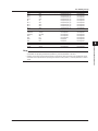
5.1 List of Commands
Command
:CURSor:TRENd?
:CURSor:TRENd:LINKage
Function
Queries all trend display cursor measurement settings.
Sets or queries the on/off status of the cursor position linkage on the trend
display.
:CURSor:TRENd:POSition<x>
Sets or queries the position of the specified cursor on the trend display.
:CURSor:TRENd[:STATe]
Sets or queries the on/off status of the cursor display on the trend display.
:CURSor:TRENd:TRACe<x>
Sets or queries the target of the specified cursor on the trend display.
:CURSor:TRENd:{X<x>|Y<x>|DY}?
Queries the measured value of the specified cursor on the trend display.
:CURSor:WAVE?
Queries all waveform display cursor measurement settings.
:CURSor:WAVE:LINKage
Sets or queries the on/off status of the cursor position linkage on the
waveform display.
:CURSor:WAVE:PATH
Sets or queries the cursor path on the waveform display.
:CURSor:WAVE:POSition<x>
Sets or queries the position of the specified cursor on the waveform display.
:CURSor:WAVE[:STATe]
Sets or queries the on/off status of the cursor display on the waveform
display.
:CURSor:WAVE:TRACe<x>
Sets or queries the target of the specified cursor on the waveform display.
:CURSor:WAVE:{X<x>|DX|PERDt|Y<x Queries the measured value of the specified cursor on the waveform display.
>|DY}?
DISPlay Group
:DISPlay?
:DISPlay:BAR?
:DISPlay:BAR:FORMat
:DISPlay:BAR:ITEM<x>?
:DISPlay:BAR:ITEM<x>[:FUNCtion]
:DISPlay:BAR:ITEM<x>:SCALing?
:DISPlay:BAR:ITEM<x>:SCALing:
MODE
:DISPlay:BAR:ITEM<x>:SCALing:
VALue
:DISPlay:BAR:ITEM<x>:SCALing:
VERTical
:DISPlay:BAR:ITEM<x>:SCALing:
XAXis
:DISPlay:BAR:ORDer
:DISPlay:INFOrmation?
:DISPlay:INFOrmation:PAGE
:DISPlay:INFOrmation[:STATe]
:DISPlay:MODE
:DISPlay:NUMeric?
:DISPlay:NUMeric:CUSTom?
:DISPlay:NUMeric:CUSTom:FILE:
CDIRectory
:DISPlay:NUMeric:CUSTom:FILE:
DRIVe
:DISPlay:NUMeric:CUSTom:FILE:
FREE?
:DISPlay:NUMeric:CUSTom:FILE:
LOAD:ABORt
:DISPlay:NUMeric:CUSTom:FILE:
LOAD:BMP
:DISPlay:NUMeric:CUSTom:FILE:
LOAD:BOTH
:DISPlay:NUMeric:CUSTom:FILE:
LOAD:ITEM
:DISPlay:NUMeric:CUSTom:FILE:
PATH?
:DISPlay:NUMeric:CUSTom:FILE:
SAVE:ANAMing
5-2
Page
5-20
5-20
5-20
5-20
5-21
5-21
5-21
5-21
5-21
5-21
5-21
5-21
5-21
Queries all display settings.
Queries all bar graph display settings.
Sets or queries the bar graph display format.
Queries all the display settings of the specified bar graph.
Sets or queries the function and element of the specified bar graph item.
Queries all scaling settings for the specified bar graph.
Sets or queries the scaling mode of the specified bar graph.
5-22
5-22
5-22
5-22
5-22
5-22
5-22
Sets or queries the upper limit of the manual scaling of the specified bar
graph.
Sets or queries the vertical scaling mode of the specified bar graph.
5-22
5-23
Sets or queries the position of the X axis of the specified bar graph.
5-23
Sets or queries the displayed starting and ending harmonic orders of the bar
graphs.
Queries all setup parameter list display settings.
Sets or queries the displayed page of the setup parameter list display.
Sets or queries the on/off status of the setup parameter list display.
Sets or queries the display mode.
Queries all numeric display settings.
Queries all numeric display settings in custom display mode.
Changes the directory that files are loaded from or saved to for the numeric
display in custom display mode.
Sets the drive that files are loaded from or saved to for the numeric display in
custom display mode.
Queries the amount of free space (in bytes) on the drive that files are loaded
from or saved to for the numeric display in custom display mode.
Aborts a file loading operation for the numeric display in custom display
mode.
Loads the specified background file for the numeric display in custom display
mode.
Loads the specified display configuration and background files for the
numeric display in custom display mode.
Loads the specified display configuration file for the numeric display in
custom display mode.
Queries the absolute path of the directory that files are loaded from or saved
to for the numeric display in custom display mode.
Sets or queries the automatic file name generation feature for saving display
configuration files of the numeric display in custom display mode.
5-23
5-23
5-23
5-23
5-23
5-24
5-24
5-24
5-24
5-24
5-24
5-24
5-24
5-24
5-24
5-25
IM WT1801-17EN
5.1 List of Commands
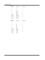
Command
:DISPlay:NUMeric:CUSTom:FILE:
SAVE:ITEM
:DISPlay:NUMeric:CUSTom:
ITEM<x>?
:DISPlay:NUMeric:CUSTom:
ITEM<x>:COLor
:DISPlay:NUMeric:CUSTom:
ITEM<x>[:FUNCtion]
:DISPlay:NUMeric:CUSTom:
ITEM<x>:POSition
:DISPlay:NUMeric:CUSTom:
ITEM<x>:SIZE
:DISPlay:NUMeric:CUSTom:PAGE
IM WT1801-17EN
Page
5-25
1
5-25
5-25
2
5-26
5-26
5-26
3
5-26
5-27
4
5-27
5-27
5-27
5-27
5-27
5-27
5-27
5-28
5
Commands
Function
Saves the specified display configuration file for the numeric display in
custom display mode.
Queries all the settings of the specified display item of the numeric display in
custom display mode.
Sets or queries the font color of the specified display item of the numeric
display in custom display mode.
Sets or queries the display item (numeric item or string) of the numeric
display in custom display mode.
Sets or queries the display position of the specified display item of the
numeric display in custom display mode.
Sets or queries the font size of the specified display item of the numeric
display in custom display mode.
Sets or queries the displayed page of the numeric display in custom display
mode.
:DISPlay:NUMeric:CUSTom:PERPage Sets or queries the number of items displayed per page of the numeric
display in custom display mode.
:DISPlay:NUMeric:CUSTom:TOTal
Sets or queries the total number of display items of the numeric display in
custom display mode.
:DISPlay:NUMeric:FRAMe
Sets or queries the on/off status of the numeric display’s data section frame.
:DISPlay:NUMeric:NORMal?
Queries all numeric display settings.
:DISPlay:NUMeric[:NORMal]:ALL? Queries all settings of the numeric display in All Items display mode.
:DISPlay:NUMeric[:NORMal]:ALL: Queries all column settings of the numeric display in All Items display mode.
COLumn?
:DISPlay:NUMeric[:NORMal]:ALL: Sets or queries the on/off status of the column display all feature of the
COLumn:DAELem
numeric display in All Items display mode.
:DISPlay:NUMeric[:NORMal]:ALL: Sets or queries the on/off status of column scrolling of the numeric display in
COLumn:SCRoll
All Items display mode.
:DISPlay:NUMeric[:NORMal]:ALL: Sets or queries the cursor position on the numeric display in All Items display
CURSor
mode.
:DISPlay:NUMeric[:NORMal]:ALL: Sets or queries the displayed harmonic order on the harmonic measurement
ORDer
function display page of the numeric display in All Items display mode.
:DISPlay:NUMeric[:NORMal]:ALL: Sets or queries the displayed page of the numeric display in All Items display
PAGE
mode.
:DISPlay:NUMeric[:NORMal]:
Sets or queries the numeric display format.
FORMat
:DISPlay:NUMeric[:NORMal]:LIST? Queries all numeric display settings in the list display modes.
:DISPlay:NUMeric[:NORMal]:LIST: Sets or queries the cursor position on the numeric display in the list display
CURSor
modes.
:DISPlay:NUMeric[:NORMal]:LIST: Sets or queries the cursor position of the header section on the numeric
HEADer
display in the list display modes.
:DISPlay:NUMeric[:NORMal]:LIST: Sets or queries the specified display item (function and element) on the
ITEM<x>
numeric display in the list display modes.
:DISPlay:NUMeric[:NORMal]:LIST: Sets or queries the harmonic order cursor position of the data section on the
ORDer
numeric display in the list display modes.
:DISPlay:NUMeric[:NORMal]:
Queries all numeric display settings in matrix display mode.
MATRix?
:DISPlay:NUMeric[:NORMal]:
Queries all column settings of the numeric display in matrix display mode.
MATRix:COLumn?
:DISPlay:NUMeric[:NORMal]:
Sets or queries the specified column display item of the numeric display in
MATRix:COLumn:ITEM<x>
matrix display mode.
:DISPlay:NUMeric[:NORMal]:
Sets or queries the number of columns of the numeric display in matrix
MATRix:COLumn:NUMber
display mode.
:DISPlay:NUMeric[:NORMal]:
Resets the column display items to their default values on the numeric
MATRix:COLumn:RESet
display in matrix display mode.
:DISPlay:NUMeric[:NORMal]:
Sets or queries the cursor position on the numeric display in matrix display
MATRix:CURSor
mode.
:DISPlay:NUMeric[:NORMal]:
Sets or queries the specified display item (function and harmonic order) on
MATRix:ITEM<x>
the numeric display in matrix display mode.
:DISPlay:NUMeric[:NORMal]:
Sets or queries the displayed page of the numeric display in matrix display
MATRix:PAGE
mode.
:DISPlay:NUMeric[:NORMal]:
Presets the display order pattern of displayed items on the numeric display
MATRix:PRESet
in matrix display mode.
6
App
5-28
5-28
5-28
5-28
5-28
5-29
5-29
5-29
5-29
5-29
5-29
5-30
5-30
5-30
5-30
5-30
5-31
5-3
Index
5.1 List of Commands
Command
:DISPlay:NUMeric[:NORMal]:{VAL4
|VAL8|VAL16}?
:DISPlay:NUMeric[:NORMal]:{VAL4
|VAL8|VAL16}:CURSor
:DISPlay:NUMeric[:NORMal]:{VAL4
|VAL8|VAL16}:ITEM<x>
:DISPlay:NUMeric[:NORMal]:{VAL4
|VAL8|VAL16}:PAGE
:DISPlay:NUMeric[:NORMal]:{VAL4
|VAL8|VAL16}:PRESet
:DISPlay:TRENd?
:DISPlay:TRENd:ALL
:DISPlay:TRENd:CLEar
:DISPlay:TRENd:FORMat
:DISPlay:TRENd:ITEM<x>?
:DISPlay:TRENd:ITEM<x>[:
FUNCtion]
:DISPlay:TRENd:ITEM<x>:SCALing?
:DISPlay:TRENd:ITEM<x>:SCALing:
MODE
:DISPlay:TRENd:ITEM<x>:SCALing:
VALue
:DISPlay:TRENd:T<x>
:DISPlay:TRENd:TDIV
:DISPlay:VECTor?
:DISPlay:VECTor:FORMat
:DISPlay:VECTor:ITEM<x>?
:DISPlay:VECTor:ITEM<x>:OBJect
:DISPlay:VECTor:
ITEM<x>:{UMAG|IMAG}
:DISPlay:VECTor:NUMeric
:DISPlay:WAVE?
:DISPlay:WAVE:ALL
:DISPlay:WAVE:FORMat
:DISPlay:WAVE:GRATicule
:DISPlay:WAVE:INTerpolate
:DISPlay:WAVE:MAPPing?
:DISPlay:WAVE:MAPPing[:MODE]
:DISPlay:WAVE:MAPPing:{U<x>|I<x
>|SPEed|TORQue|AUX<x>}
:DISPlay:WAVE:POSition?
:DISPlay:WAVE:
POSition:{U<x>|I<x>}
:DISPlay:WAVE:
POSition:{UALL|IALL}
:DISPlay:WAVE:SVALue
:DISPlay:WAVE:TDIV
:DISPlay:WAVE:TLABel
:DISPlay:WAVE:TRIGger?
:DISPlay:WAVE:TRIGger:LEVel
:DISPlay:WAVE:TRIGger:MODE
:DISPlay:WAVE:TRIGger:SLOPe
:DISPlay:WAVE:TRIGger:SOURce
:DISPlay:WAVE:{U<x>|I<x>|SPEed|
TORQue|AUX<x>}
:DISPlay:WAVE:VZoom?
:DISPlay:WAVE:VZoom:{U<x>|I<x>}
:DISPlay:WAVE:VZoom:{UALL|IALL}
5-4
Function
Queries all numeric display settings in 4 Items, 8 Items, or 16 Items display
mode.
Sets or queries the cursor position on the numeric display in 4 Items, 8
Items, or 16 Items display mode.
Sets or queries the function, element, and harmonic order of the specified
numeric display item in 4 Items, 8 Items, or 16 Items display mode.
Sets or queries the displayed page of the numeric display in 4 Items, 8 Items,
or 16 Items display mode.
Presets the display order pattern of displayed items on the numeric display
in 4 Items, 8 Items, or 16 Items display mode.
Queries all trend display settings.
Collectively sets the on/off status of all trends.
Clears all trends.
Sets or queries the display format of all trends.
Queries all settings for the specified trend.
Sets or queries the function, element, and harmonic order of the specified
trend item.
Queries all scaling settings for the specified trend.
Sets or queries the scaling mode of the specified trend.
Page
5-31
Sets or queries the upper and lower limits of the manual scaling of the
specified trend.
Sets or queries the on/off status of the specified trend.
Sets or queries the trend horizontal axis (T/div).
Queries all vector display settings.
Sets or queries the display format of all vectors.
Queries all settings for the specified vector.
Sets or queries the wiring unit that is displayed using the specified vector.
Sets or queries the voltage or current zoom factor for the vector display.
5-33
Sets or queries the on/off status of the numeric data display on the vector
display.
Queries all waveform display settings.
Collectively sets the on/off status of all waveform displays.
Sets or queries the display format of all waveforms.
Sets or queries the graticule (grid) type.
Sets or queries the waveform interpolation method.
Queries all split screen waveform mapping settings.
Sets or queries the split screen waveform mapping mode.
Sets or queries the split screen voltage, current, rotating speed, torque, or
auxiliary signal waveform mapping setting.
Queries all waveform vertical position (center position level) settings.
Sets or queries the vertical position (center position level) of the specified
element’s voltage or current waveform.
Collectively sets the vertical positions (center position levels) of the voltage
or current waveforms of all elements.
Sets or queries the on/off status of the scale value display.
Sets or queries the waveform Time/div value.
Sets or queries the on/off status of the waveform labels.
Queries all trigger settings.
Sets or queries the trigger level.
Sets or queries the trigger mode.
Sets or queries the trigger slope.
Sets or queries the trigger source.
Sets or queries the on/off status of the voltage, current, rotating speed,
torque, or auxiliary signal waveform display.
Queries all waveform vertical zoom factor settings.
Sets or queries the vertical zoom factor of the specified element’s voltage or
current waveform.
Collectively sets the vertical zoom factor for the voltage or current waveforms
of all elements.
5-31
5-31
5-32
5-32
5-32
5-32
5-32
5-32
5-32
5-32
5-33
5-33
5-33
5-33
5-33
5-33
5-33
5-33
5-34
5-34
5-34
5-34
5-34
5-34
5-34
5-34
5-34
5-34
5-34
5-35
5-35
5-35
5-35
5-35
5-35
5-35
5-35
5-35
5-35
5-36
5-36
5-36
5-36
IM WT1801-17EN
5.1 List of Commands
Command
FILE Group
Page
Queries all file operation settings.
Changes the current directory.
Deletes the specified screen image data file.
5-41
5-41
5-41
Deletes the specified numeric data file.
Deletes the specified setup parameter file.
Deletes the specified stored numeric data file.
5-41
5-41
5-41
Deletes the specified waveform display data file.
Sets the current drive.
Sets or queries the file list filter.
Queries the free space (in bytes) on the current drive.
Aborts a file loading operation.
Loads the specified setup parameter file.
Queries the absolute path of the current directory.
Queries all file save settings.
Aborts a file saving operation.
Sets or queries the auto naming feature for saving files.
Sets or queries the comment that will be added to files that are saved.
Saves numeric data to a file.
Sets or queries the method that is used to select which items are saved
when numeric data is saved to a file.
:FILE:SAVE:NUMeric:NORMal?
Queries all numeric data file save settings (for the manual save item
selection method).
:FILE:SAVE:NUMeric:NORMal:ALL
Collectively sets the on/off status of the output of all element functions when
numeric data is saved to a file.
:FILE:SAVE:NUMeric:NORMal:{ELEM Sets or queries the on/off status of the output of the specified element or
ent<x>|SIGMA|SIGMB|SIGMC}
wiring unit ΣA, ΣB, or ΣC when numeric data is saved to a file.
:FILE:SAVE:NUMeric:
Sets or queries the on/off status of the specified function’s output when
NORMal:<Function>
numeric data is saved to a file.
:FILE:SAVE:NUMeric:NORMal:
Presets the output on/off pattern of the element functions to be used when
PRESet<x>
numeric data is saved to a file.
:FILE:SAVE:SETup[:EXECute]
Saves setup parameters to a file.
:FILE:SAVE:WAVE[:EXECute]
Saves waveform display data to a file.
HARMonics Group
:HARMonics<x>?
:HARMonics<x>:CONFigure?
:HARMonics<x>:CONFigure[:ALL]
:HARMonics<x>:CONFigure:
ELEMent<x>
:HARMonics<x>:CONFigure:{SIGMA|
SIGMB|SIGMC}
:HARMonics<x>:ORDer
:HARMonics<x>:PLLSource
:HARMonics<x>:THD
HCOPy Group
:HCOPy?
:HCOPy:ABORt
:HCOPy:AUTO?
:HCOPy:AUTO:COUNt
:HCOPy:AUTO:INTerval
:HCOPy:AUTO:MODE
:HCOPy:AUTO:PASTart
:HCOPy:AUTO:{STARt|END}
:HCOPy:AUTO[:STATe]
IM WT1801-17EN
5-41
5-41
5-41
5-41
5-41
5-41
5-41
5-42
5-42
5-42
5-42
5-42
5-42
5-42
5-42
2
3
4
5
6
App
5-42
5-42
5-43
5-43
5-43
Queries all harmonic measurement settings.
Queries the harmonic measurement groups of all elements.
Collectively sets the harmonic measurement group of all elements.
Sets or queries the harmonic measurement group of the specified element.
5-44
5-44
5-44
5-44
Collectively sets the harmonic measurement group of all the elements that
belong to the specified wiring unit (ΣA, ΣB, or ΣC).
Sets or queries the maximum and minimum harmonic orders that are
analyzed.
Sets or queries the PLL source.
Sets or queries the equation used to compute the THD (total harmonic
distortion).
5-44
Queries all print settings.
Aborts a print operation.
Queries all auto print settings.
Sets or queries the auto print count.
Sets or queries the auto print interval.
Sets or queries the auto print operation mode.
Sets or queries whether printing starts when auto printing starts.
Sets or queries the printing start or end time for real-time printing mode.
Sets or queries the auto print feature’s on/off status.
1
Commands
:FILE?
:FILE:CDIRectory
:FILE:DELete:
IMAGe:{BMP|PNG|JPEG}
:FILE:DELete:NUMeric:ASCii
:FILE:DELete:SETup
:FILE:DELete:
STORe:{DATA|HEADer}
:FILE:DELete:WAVE:ASCii
:FILE:DRIVe
:FILE:FILTer
:FILE:FREE?
:FILE:LOAD:ABORt
:FILE:LOAD:SETup
:FILE:PATH?
:FILE:SAVE?
:FILE:SAVE:ABORt
:FILE:SAVE:ANAMing
:FILE:SAVE:COMMent
:FILE:SAVE:NUMeric[:EXECute]
:FILE:SAVE:NUMeric:ITEM
Function
5-44
5-44
5-44
5-45
5-45
5-45
5-45
5-45
5-45
5-45
5-45
5-46
5-5
Index
5.1 List of Commands
Command
:HCOPy:AUTO:TEVent
:HCOPy:COMMent
:HCOPy:EXECute
:HCOPy:PRINter?
:HCOPy:PRINter:FEED
:HCOPy:PRINter:FORMat
HOLD Group
:HOLD
IMAGe Group
:IMAGe?
:IMAGe:ABORt
:IMAGe:COLor
:IMAGe:COMMent
:IMAGe:EXECute
:IMAGe:FORMat
:IMAGe:SAVE?
:IMAGe:SAVE:ANAMing
:IMAGe:SAVE:CDIRectory
:IMAGe:SAVE:DRIVe
:IMAGe:SAVE:FREE?
:IMAGe:SAVE:NAME
:IMAGe:SAVE:PATH?
:IMAGe:SEND?
INPut Group
:INPut?
[:INPut]:CFACtor
[:INPut]:CURRent?
[:INPut]:CURRent:AUTO?
[:INPut]:CURRent:AUTO[:ALL]
[:INPut]:CURRent:AUTO:
ELEMent<x>
[:INPut]:CURRent:
AUTO:{SIGMA|SIGMB|SIGMC}
[:INPut]:CURRent:CONFig?
[:INPut]:CURRent:CONFig[:ALL]
[:INPut]:CURRent:CONFig:
ELEMent<x>
[:INPut]:CURRent:EXTSensor?
[:INPut]:CURRent:EXTSensor:
CONFig?
[:INPut]:CURRent:EXTSensor:
CONFig[:ALL]
[:INPut]:CURRent:EXTSensor:
CONFig:ELEMent<x>
[:INPut]:CURRent:EXTSensor:
DISPlay
[:INPut]:CURRent:EXTSensor:
POJump?
[:INPut]:CURRent:EXTSensor:
POJump[:ALL]
[:INPut]:CURRent:EXTSensor:
POJump:ELEMent<x>
5-6
Function
Sets or queries the event that the event-synchronized print mode will trigger
on.
Sets or queries the comment displayed at the bottom of the screen.
Executes a print operation.
Queries all print settings for the built-in printer.
Executes a paper feed on the built-in printer.
Sets or queries the contents that will be printed from the built-in printer.
Page
5-46
5-46
5-46
5-46
5-46
5-46
Sets or queries the on/off status of the output hold feature for display,
communication, and other types of data.
5-47
Queries all screen image data output settings.
Aborts a screen image data output operation.
Sets or queries the color tone of the screen image data that will be saved.
Sets or queries the comment displayed at the bottom of the screen.
Executes a screen image data output operation.
Sets or queries the format of the screen image data that will be saved.
Queries all screen image data save settings.
Sets or queries the auto naming feature for saving files.
Changes the directory that screen image data is saved to.
Sets the drive that screen image data is saved to.
Queries the free space (in bytes) on the drive that the screen image data is
saved to.
Sets or queries the name of the file that will be saved.
Queries the absolute path of the directory that the screen image data is
saved to.
Queries the screen image data.
5-48
5-48
5-48
5-48
5-48
5-48
5-48
5-48
5-48
5-48
5-48
Queries all input element settings.
Sets or queries the crest factor.
Queries all electric current measurement settings.
Queries the electric current auto range on/off statuses of all elements.
Collectively sets the electric current auto range on/off status of all elements.
Sets or queries the electric current auto range on/off status of the specified
element.
Collectively sets the electric current auto range on/off status of all the
elements that belong to the specified wiring unit (ΣA, ΣB, or ΣC).
Queries the valid electric current ranges of all elements.
Collectively sets the valid electric current range of all elements.
Sets or queries the valid electric current range of the specified element.
5-50
5-50
5-50
5-50
5-50
5-50
Queries all external current sensor range settings.
Queries the valid external current sensor ranges of all elements.
5-51
5-51
Collectively sets the valid external current sensor range of all elements.
5-51
Sets or queries the valid external current sensor ranges of the specified
element.
Sets or queries the display mode of the external current sensor range.
5-51
5-49
5-49
5-49
5-50
5-50
5-50
5-51
5-51
Queries the jump destination ranges of all elements that are used when a
5-51
current peak over-range occurs.
Collectively sets the jump destination range of all elements that is used when 5-52
a current peak over-range occurs.
Sets or queries the jump destination range of the specified element that is
5-52
used when a current peak over-range occurs.
IM WT1801-17EN
5.1 List of Commands
Command
[:INPut]:CURRent:POJump?
[:INPut]:CURRent:POJump[:ALL]
IM WT1801-17EN
Page
5-52
Collectively sets the electric current range of all the elements that belong to
the specified wiring unit (ΣA, ΣB, or ΣC).
Queries the external current sensor conversion ratios of all elements.
Collectively sets the external current sensor conversion ratios of all elements.
Sets or queries the external current sensor conversion ratio of the specified
element.
Collectively sets the external current sensor conversion ratios of all the
elements that belong to the specified wiring unit (ΣA, ΣB, or ΣC).
Sets or queries the element whose measurement range will be set.
Queries all input filter settings.
Queries the frequency filters of all elements.
Collectively sets the frequency filter of all elements.
Sets or queries the frequency filter of the specified element.
5-53
5-52
5-52
5-52
5-53
5-53
5-53
5-53
5-53
2
3
4
5-54
5-54
5-54
5-54
5-54
5-54
Queries the line filters of all elements.
Collectively sets the line filter of all elements.
Sets or queries the line filter of the specified element.
5-54
5-54
5-54
Collectively sets the line filter of all the elements that belong to the specified
wiring unit (ΣA, ΣB, or ΣC).
Sets or queries the on/off status of independent input element configuration.
Queries the input element type.
Queries the status of the NULL operation of rotating speed, torque, or AUX.
5-55
Queries the status of the voltage or current NULL operation of the specified
element.
Sets or queries the on/off status of the NULL feature.
Queries all settings for the target of the NULL feature.
Sets or queries the selection mode for the target of the NULL feature.
Sets or queries the target of the NULL operation (rotating speed, torque, or
AUX).
Sets or queries the target of the voltage or current NULL operation of the
specified element.
Collectively sets the target of the voltage or current NULL operation of all
elements.
Queries the peak over-range information.
Queries all scaling settings.
Queries the on/off statuses of the scaling of all elements.
Collectively sets the on/off status of the scaling of all elements.
Sets or queries the on/off status of the scaling of the specified element.
1
5-55
5-55
5-55
5-55
5-55
5-55
5-55
5-55
5-56
5-56
5-56
5-56
5-56
5-56
5-56
Queries the VT ratios, CT ratios, or power coefficients of all elements.
5-56
Collectively sets the VT ratio, CT ratio, or power coefficient of all elements.
5-56
Sets or queries the VT ratio, CT ratio, or power coefficient of the specified
element.
5-56
Collectively sets the VT ratio, CT ratio, or power coefficient of all the
elements that belong to the specified wiring unit (ΣA, ΣB, or ΣC).
Queries the synchronization sources of all elements.
5-57
5-57
5-7
5
Commands
[:INPut]:CURRent:POJump:
ELEMent<x>
[:INPut]:CURRent:RANGe?
[:INPut]:CURRent:RANGe[:ALL]
[:INPut]:CURRent:RANGe:
ELEMent<x>
[:INPut]:CURRent:RANGe:{SIGMA|S
IGMB|SIGMC}
[:INPut]:CURRent:SRATio?
[:INPut]:CURRent:SRATio[:ALL]
[:INPut]:CURRent:SRATio:
ELEMent<x>
[:INPut]:CURRent:SRATio:{SIGMA|
SIGMB|SIGMC}
[:INPut]:ESELect
[:INPut]:FILTer?
[:INPut]:FILTer:FREQuency?
[:INPut]:FILTer:FREQuency[:ALL]
[:INPut]:FILTer:FREQuency:
ELEMent<x>
[:INPut]:FILTer:LINE?
[:INPut]:FILTer[:LINE][:ALL]
[:INPut]:FILTer[:LINE]:
ELEMent<x>
[:INPut]:FILTer[:LINE]:{SIGMA|S
IGMB|SIGMC}
[:INPut]:INDependent
[:INPut]:MODUle?
[:INPut]:NULL:CONDition:{SPEed|
TORQue|AUX<x>}
[:INPut]:NULL:
CONDition:{U<x>|I<x>}
[:INPut]:NULL[:STATe]
[:INPut]:NULL:TARGet?
[:INPut]:NULL:TARGet[:MODE]
[:INPut]:NULL:TARGet:{SPEed|TOR
Que|AUX<x>}
[:INPut]:NULL:
TARGet:{U<x>|I<x>}
[:INPut]:NULL:
TARGet:{UALL|IALL}
[:INPut]:POVer?
[:INPut]:SCALing?
[:INPut]:SCALing:STATe?
[:INPut]:SCALing[:STATe][:ALL]
[:INPut]:SCALing[:STATe]:
ELEMent<x>
[:INPut]:
SCALing:{VT|CT|SFACtor}?
[:INPut]:
SCALing:{VT|CT|SFACtor}[:ALL]
[:INPut]:
SCALing:{VT|CT|SFACtor}:
ELEMent<x>
[:INPut]:SCALing:{VT|CT|SFACtor
}:{SIGMA|SIGMB|SIGMC}
[:INPut]:SYNChronize?
Function
Queries the jump destination ranges of all elements that are used when a
current peak over-range occurs.
Collectively sets the jump destination range of all elements that is used when
a current peak over-range occurs.
Sets or queries the jump destination range of the specified element that is
used when a current peak over-range occurs.
Queries the electric current ranges of all elements.
Collectively sets the electric current range of all elements.
Sets or queries the electric current range of the specified element.
6
App
Index
5.1 List of Commands
Command
[:INPut]:SYNChronize[:ALL]
[:INPut]:SYNChronize:ELEMent<x>
[:INPut]:SYNChronize:{SIGMA|SIG
MB|SIGMC}
[:INPut]:VOLTage?
[:INPut]:VOLTage:AUTO?
[:INPut]:VOLTage:AUTO[:ALL]
[:INPut]:VOLTage:AUTO:
ELEMent<x>
[:INPut]:VOLTage:
AUTO:{SIGMA|SIGMB|SIGMC}
[:INPut]:VOLTage:CONFig?
[:INPut]:VOLTage:CONFig[:ALL]
[:INPut]:VOLTage:CONFig:
ELEMent<x>
[:INPut]:VOLTage:POJump?
[:INPut]:VOLTage:POJump[:ALL]
Function
Collectively sets the synchronization source of all elements.
Sets or queries the synchronization source of the specified element.
Collectively sets the synchronization source of all the elements that belong
to the specified wiring unit (ΣA, ΣB, or ΣC).
Queries all voltage measurement settings.
Queries the voltage auto range on/off statuses of all elements.
Collectively sets the voltage auto range on/off status of all elements.
Sets or queries the voltage auto range on/off status of the specified element.
Page
5-57
5-57
5-57
Collectively sets the voltage auto range on/off status of all elements.
5-57
Queries the valid voltage ranges of all elements.
Collectively sets the valid voltage range of all elements.
Sets or queries the valid voltage ranges of the specified element.
5-57
5-58
5-58
Queries the jump destination ranges of all elements that are used when a
voltage peak over-range occurs.
Collectively sets the jump destination range of all elements that is used when
a voltage peak over-range occurs.
Sets or queries the jump destination range of the specified element that is
used when a voltage peak over-range occurs.
Queries the voltage ranges of all elements.
Collectively sets the voltage range of all elements.
Sets or queries the voltage range of the specified element.
5-58
[:INPut]:VOLTage:POJump:
ELEMent<x>
[:INPut]:VOLTage:RANGe?
[:INPut]:VOLTage:RANGe[:ALL]
[:INPut]:VOLTage:RANGe:
ELEMent<x>
[:INPut]:VOLTage:RANGe:{SIGMA|S Collectively sets the voltage range of all the elements that belong to the
IGMB|SIGMC}
specified wiring unit (ΣA, ΣB, or ΣC).
[:INPut]:WIRing
Sets or queries the wiring system.
INTEGrate Group
:INTEGrate?
:INTEGrate:ACAL
:INTEGrate:INDependent
:INTEGrate:MODE
:INTEGrate:QMODe?
5-58
5-58
5-58
5-58
5-59
5-59
5-59
Queries all integration settings.
Sets or queries the on/off status of integration auto calibration.
Sets or queries the on/off status of independent element integration.
Sets or queries the integration mode.
Queries the electric current modes for electric current integration of all
elements.
:INTEGrate:QMODe[:ALL]
Collectively sets the electric current mode for electric current integration of all
elements.
:INTEGrate:QMODe:ELEMent<x>
Sets or queries the electric current mode for electric current integration of the
specified element.
:INTEGrate:RESet
Resets the integrated value.
:INTEGrate:RTALl:{STARt|END}
Collectively sets the integration start or end time of all elements for real-time
integration mode.
:INTEGrate:RTIMe<x>?
Queries the integration start and end times for real-time integration mode.
:INTEGrate:RTIMe<x>:{STARt|END} Sets or queries the integration start or end time for real-time integration
mode.
:INTEGrate:STARt
Starts integration.
:INTEGrate:STATe?
Queries the integration status.
:INTEGrate:STOP
Stops integration.
:INTEGrate:TIMer<x>
Sets or queries the integration timer value.
:INTEGrate:TMALl
Collectively sets the integration timer of all elements.
:INTEGrate:WPTYpe?
Queries the watt-hour integration methods for each polarity (WP+/WP–) of all
elements.
:INTEGrate:WPTYpe[:ALL]
Collectively sets the watt-hour integration method for each polarity (WP+/WP
–) of all elements.
:INTEGrate:WPTYpe:ELEMent<x>
Sets or queries the watt-hour integration method for each polarity (WP+/WP–)
of the specified element.
5-8
5-57
5-57
5-57
5-57
5-60
5-60
5-60
5-60
5-60
5-60
5-60
5-60
5-60
5-61
5-61
5-61
5-61
5-62
5-62
5-62
5-62
5-62
5-62
IM WT1801-17EN
5.1 List of Commands
Command
MEASure Group
Page
Queries all computation settings.
Queries all averaging settings.
Sets or queries the averaging coefficient.
Sets or queries the on/off status of averaging.
Sets or queries the averaging type.
Queries all delta computation settings.
Sets or queries the voltage or current mode that is used in delta computation.
Sets or queries the delta computation mode for wiring unit ΣA, ΣB, or ΣC.
5-63
5-63
5-63
5-63
5-63
5-63
5-63
5-63
Queries all efficiency computation settings.
Sets or queries the efficiency equation.
Sets or queries the user-defined parameters used in the efficiency equation.
Queries all the settings of the specified user-defined event.
Queries all the settings of the specified user-defined event’s expression.
Sets or queries the specified user-defined event’s expression (compound
condition type).
Sets or queries the on/off status of the logic inversion of the specified userdefined event’s expression (compound condition type).
Sets or queries the target item of the specified user-defined event’s
expression (range-defined type).
Sets or queries the range of the specified user-defined event’s expression
(range-defined type).
Queries the specified user-defined event’s expression as a string.
5-64
5-64
5-64
5-64
5-64
5-64
Sets or queries the specified user-defined event’s expression type.
5-65
Sets or queries the string that is displayed when the specified user-defined
event’s condition is not met.
:MEASure:EVENt<x>:NAME
Sets or queries the specified user-defined event’s name.
:MEASure:EVENt<x>[:STATe]
Sets or queries the on/off status of the specified user-defined event.
:MEASure:EVENt<x>:TLABel
Sets or queries the string that is displayed when the specified user-defined
event’s condition is met.
:MEASure:FREQuency?
Queries all frequency measurement settings.
:MEASure:FREQuency:ITEM<x>
Sets or queries the element whose frequency will be measured.
:MEASure:FUNCtion<x>?
Queries all the settings of the specified user-defined function.
:MEASure:FUNCtion<x>:EXPRession Sets or queries the equation of the specified user-defined function.
:MEASure:FUNCtion<x>:NAME
Sets or queries the name of the specified user-defined function.
:MEASure:FUNCtion<x>[:STATe]
Sets or queries the on/off status of the specified user-defined function.
:MEASure:FUNCtion<x>:UNIT
Sets or queries the unit that is added to the computation result of the
specified user-defined function.
:MEASure:MHOLd
Sets or queries the on/off status of the MAX HOLD feature used in userdefined functions.
:MEASure:PC?
Queries all Pc (Corrected Power) computation settings.
:MEASure:PC:IEC
Sets or queries the Pc (Corrected Power) equation.
:MEASure:PC:P<x>
Sets or queries a Pc (Corrected Power) equation parameter.
:MEASure:PHASe
Sets or queries the display format of the phase difference.
:MEASure:SAMPling
Sets or queries the sampling frequency.
:MEASure:SFORmula
Sets or queries the equation used to compute S (apparent power).
:MEASure:SQFormula
Sets or queries the equation used to compute S (apparent power) and Q
(reactive power).
:MEASure:SYNChronize
Sets or queries the synchronized measurement mode.
IM WT1801-17EN
5-64
5-65
5-65
5-65
5-65
5-65
5-65
5-66
5-66
5-66
5-66
5-66
5-66
5-66
5-66
5-66
5-67
5-67
5-67
5-67
5-67
5-67
5-67
5-67
5-9
1
2
3
4
5
Commands
:MEASure?
:MEASure:AVERaging?
:MEASure:AVERaging:COUNt
:MEASure:AVERaging[:STATe]
:MEASure:AVERaging:TYPE
:MEASure:DMeasure?
:MEASure:DMeasure:MODE
:MEASure:DMeasure:{SIGMA|SIGMB|
SIGMC}
:MEASure:EFFiciency?
:MEASure:EFFiciency:ETA<x>
:MEASure:EFFiciency:UDEF<x>
:MEASure:EVENt<x>?
:MEASure:EVENt<x>:EXPRession?
:MEASure:EVENt<x>:EXPRession:
CONDition
:MEASure:EVENt<x>:EXPRession:
INVerse
:MEASure:EVENt<x>:EXPRession:
ITEM
:MEASure:EVENt<x>:EXPRession:
LIMit<x>
:MEASure:EVENt<x>:EXPRession:
STRing?
:MEASure:EVENt<x>:EXPRession:
TYPE
:MEASure:EVENt<x>:FLABel
Function
6
App
Index
5.1 List of Commands
Command
MOTor Group
:MOTor?
:MOTor:EANGle?
:MOTor:EANGle:CORRection?
:MOTor:EANGle:CORRection:
AENTer?
:MOTor:EANGle:CORRection:
AENTer[:EXECute]
:MOTor:EANGle:CORRection:
AENTer:TARGet
:MOTor:EANGle:CORRection:CLEar
:MOTor:EANGle:CORRection[:
VALue]
:MOTor:EANGle[:STATe]
:MOTor:FILTer?
:MOTor:FILTer[:LINE]
:MOTor:PM?
:MOTor:PM:SCALing
:MOTor:PM:UNIT
:MOTor:POLE
:MOTor:SPEed?
:MOTor:SPEed:AUTO
:MOTor:SPEed:LSCale?
:MOTor:SPEed:LSCale:AVALue
:MOTor:SPEed:LSCale:BVALue
:MOTor:SPEed:LSCale:CALCulate?
:MOTor:SPEed:LSCale:CALCulate:{
P1X|P1Y|P2X|P2Y}
:MOTor:SPEed:LSCale:CALCulate:
EXECute
:MOTor:SPEed:PRANge
:MOTor:SPEed:PULSe
:MOTor:SPEed:RANGe
:MOTor:SPEed:SCALing
:MOTor:SPEed:TYPE
:MOTor:SPEed:UNIT
:MOTor:SSPeed
:MOTor:SYNChronize
:MOTor:TORQue?
:MOTor:TORQue:AUTO
:MOTor:TORQue:LSCale?
:MOTor:TORQue:LSCale:AVALue
:MOTor:TORQue:LSCale:BVALue
:MOTor:TORQue:LSCale:CALCulate?
:MOTor:TORQue:LSCale:CALCulate:
{P1X|P1Y|P2X|P2Y}
:MOTor:TORQue:LSCale:CALCulate:
EXECute
5-10
Function
Page
Queries all motor evaluation function settings.
Queries all electrical angle measurement settings.
Queries all electrical angle correction settings.
Queries all automatic electrical angle correction entry settings.
5-68
5-68
5-68
5-68
Executes an automatic electrical angle correction entry.
5-68
Sets or queries the target source for automatically entering the electrical
angle correction value.
Clears the electrical angle correction value.
Sets or queries the electrical angle correction value.
5-68
Sets or queries the on/off status of electrical angle measurement.
Queries all input filter settings.
Sets or queries the line filter.
Queries all motor output (Pm) settings.
Sets or queries the motor output computation scaling factor.
Sets or queries the unit that is added to the motor output computation result.
Sets or queries the motor’s number of poles.
Queries all rotating speed (Speed) settings.
Sets or queries the voltage auto range on/off status of the revolution signal
(analog input type).
Queries all revolution signal (analog input type) linear scaling settings.
Sets or queries the slope (A) of the linear scale of the revolution signal (analog
input type).
Sets or queries the offset (B) of the linear scale of the revolution signal (analog
input type).
Queries all parameter calculation settings for the linear scale of the revolution
signal (analog input type).
Sets or queries the data (Point1X, Point1Y, Point2X, or Point2Y) for
parameter calculations of the linear scale of the revolution signal (analog
input type).
Calculates parameters for the linear scale of the revolution signal (analog
input type).
Sets or queries the range of the revolution signal (pulse input type).
Sets or queries the number of pulses of the revolution signal (pulse input
type).
Sets or queries the voltage range of the revolution signal (analog input type).
Sets or queries the rotating speed computation scaling factor.
Sets or queries the revolution signal input type.
Sets or queries the unit that is added to the rotating speed computation
result.
Sets or queries the frequency measurement source for the synchronous
speed (SyncSp) computation.
Sets or queries the synchronization source for the rotating speed (Speed)
and torque (Torque) computations.
Queries all torque (Torque) settings.
Sets or queries the voltage auto range on/off status of the torque signal
(analog input type).
Queries all torque signal (analog input type) linear scaling settings.
Sets or queries the slope (A) of the linear scale of the torque signal (analog
input type).
Sets or queries the offset (B) of the linear scale of the torque signal (analog
input type).
Queries all parameter calculation settings for the linear scale of the torque
signal (analog input type).
Sets or queries the data (Point1X, Point1Y, Point2X, or Point2Y) for
parameter calculations of the linear scale of the torque signal (analog input
type).
Calculates parameters for the linear scale of the torque signal (analog input
type).
5-68
5-68
5-68
5-68
5-69
5-69
5-69
5-69
5-69
5-68
5-68
5-69
5-69
5-69
5-69
5-69
5-69
5-70
5-70
5-70
5-70
5-70
5-70
5-70
5-70
5-70
5-71
5-71
5-71
5-71
5-71
5-71
5-71
IM WT1801-17EN
5.1 List of Commands
Command
:MOTor:TORQue:PRANge
:MOTor:TORQue:RANGe
:MOTor:TORQue:RATE?
:MOTor:TORQue:
RATE:{UPPer|LOWer}
:MOTor:TORQue:SCALing
:MOTor:TORQue:TYPE
:MOTor:TORQue:UNIT
NUMeric Group
:NUMeric?
:NUMeric:FORMat
:NUMeric:HOLD
:NUMeric:LIST?
:NUMeric:LIST:CLEar
:NUMeric:LIST:NUMber
:NUMeric:LIST:ORDer
:NUMeric:LIST:PRESet
:NUMeric:LIST:SELect
:NUMeric:LIST:VALue?
:NUMeric:NORMal?
:NUMeric[:NORMal]:CLEar
:NUMeric[:NORMal]:DELete
:NUMeric[:NORMal]:ITEM<x>
:NUMeric[:NORMal]:NUMber
:NUMeric[:NORMal]:PRESet
:NUMeric[:NORMal]:VALue?
RATE Group
:RATE
STATus Group
:STATus?
:STATus:CONDition?
:STATus:EESE
:STATus:EESR?
:STATus:ERRor?
:STATus:FILTer<x>
:STATus:QENable
:STATus:QMESsage
:STATus:SPOLl?
IM WT1801-17EN
Page
5-71
5-71
5-72
5-72
Queries all numeric data output settings.
Sets or queries the numeric data format.
Sets or queries the on/off (hold/release) status of the numeric data hold
feature.
Queries all harmonic measurement numeric list data output settings.
Clears harmonic measurement numeric list data output items (sets the items
to NONE).
Deletes harmonic measurement numeric list data output items.
Sets or queries the output item (function and element) of the specified
harmonic measurement numeric list data item.
Sets or queries the number of numeric list data items that are transmitted by
:NUMeric:LIST:VALue?.
Sets or queries the maximum output harmonic order of the harmonic
measurement numeric list data.
Presets the harmonic measurement numeric list data output item pattern.
Sets or queries the output components of the harmonic measurement
numeric list data.
Queries the harmonic measurement numeric list data.
Queries all numeric data output settings.
Clears numeric data output items (sets the items to NONE).
Deletes numeric data output items.
Sets or queries the specified numeric data output item (function, element,
and harmonic order).
Sets or queries the number of numeric data items that are transmitted by the
:NUMeric[:NORMal]:VALue? command.
Presets the numeric data output item pattern.
Queries the numeric data.
5-73
5-73
5-73
5-72
5-72
5-72
1
2
3
5-74
5-74
4
5-74
5-74
5
5-74
Commands
:NUMeric:LIST:DELete
:NUMeric:LIST:ITEM<x>
Function
Sets or queries the range of the torque signal (pulse input type).
Sets or queries the voltage range of the torque signal (analog input type).
Queries all torque signal (pulse input type) rated-value settings.
Sets or queries the upper or lower limit of the rated value of the torque signal
(pulse input type).
Sets or queries the torque computation scaling factor.
Sets or queries the torque signal input type.
Sets or queries the unit that is added to the torque computation result.
5-74
5-75
5-75
5-75
5-75
5-76
5-76
5-76
5-76
5-76
5-77
Sets or queries the data update rate.
5-83
Queries all the settings for the communication status feature.
Queries the contents of the condition register.
Sets or queries the extended event enable register.
Queries the contents of the extended event register and clears the register.
Queries the error code and message of the last error that has occurred (top
of the error queue).
Sets or queries the transition filter.
Sets or queries whether messages other than errors will be stored to the
error queue (ON/OFF).
Sets or queries whether message information will be attached to the
response to the STATus:ERRor? query (ON/OFF).
Executes serial polling.
5-84
5-84
5-84
5-84
5-84
5-84
5-84
5-84
5-84
5-11
6
App
Index
5.1 List of Commands
Command
Function
Page
STORe Group
:STORe?
:STORe:COUNt
:STORe:FILE?
Queries all numeric data storage settings.
Sets or queries the storage count.
Queries all settings related to the saving of the data stored in the WT1800 to
files.
:STORe:FILE:ANAMing
Sets or queries the auto naming feature for saving stored numeric data to
files.
:STORe:FILE:CDIRectory
Changes the directory that stored numeric data is saved to.
:STORe:FILE:CONVert?
Queries all settings related to the conversion of stored numeric data files into
CSV format.
:STORe:FILE:CONVert:ABORt
Aborts the conversion of a numeric data file to CSV format.
:STORe:FILE:CONVert:AUTO
Sets or queries the on/off status of the automatic conversion of stored
numeric data files to CSV format.
:STORe:FILE:CONVert:EXECute
Converts the specified stored numeric data file to CSV format.
:STORe:FILE:DRIVe
Sets the drive that stored numeric data is saved to.
:STORe:FILE:FREE?
Queries the free space (in bytes) on the drive that the stored numeric data is
saved to.
:STORe:FILE:NAME
Sets or queries the name of the file that stored numeric data is saved to.
:STORe:FILE:PATH?
Queries the absolute path of the directory that the stored numeric data is
saved to.
:STORe:INTerval
Sets or queries the storage interval.
:STORe:NUMeric?
Queries all numeric data storage item settings.
:STORe:NUMeric:ITEM
Sets or queries the numeric data storage item selection method.
:STORe:NUMeric:NORMal?
Queries all numeric data storage item settings (for the manual selection
method).
:STORe:NUMeric[:NORMal]:ALL
Collectively sets the on/off status of the output of all element functions when
numeric data is stored.
:STORe:NUMeric[:NORMal]:{ELEMen Sets or queries the on/off status of the output of the specified element or
t<x>|SIGMA|SIGMB|SIGMC}
wiring unit ΣA, ΣB, or ΣC when numeric data is stored.
:STORe:NUMeric[:
Sets or queries the on/off status of the specified function’s output when
NORMal]:<Function>
numeric data is stored.
:STORe:NUMeric[:NORMal]:
Presets the output on/off pattern of the element functions to be used when
PRESet<x>
numeric data is stored.
:STORe:RESet
Resets the numeric data storage feature.
:STORe:RTIMe?
Queries the storage start and end times for real-time storage mode.
:STORe:RTIMe:{STARt|END}
Sets or queries the storage start or end time for real-time storage mode.
:STORe:SASTart
Sets or queries whether numeric data is stored when storage starts.
:STORe:SMODe
Sets or queries the storage mode.
:STORe:STARt
Begins the storing of numeric data.
:STORe:STATe?
Sets or queries the storage state.
:STORe:STOP
Stops the storing of numeric data.
:STORe:TEVent
Sets or queries the event that the event-synchronized storage mode will
trigger on.
SYSTem Group
:SYSTem?
:SYSTem:CLOCk?
:SYSTem:CLOCk:DISPlay
:SYSTem:CLOCk:SNTP?
:SYSTem:CLOCk:SNTP[:EXECute]
:SYSTem:CLOCk:SNTP:GMTTime
:SYSTem:CLOCk:TYPE
:SYSTem:DATE
:SYSTem:DFLow:FREQuency
:SYSTem:DFLow:MOTor
:SYSTem:DPOint
:SYSTem:ECLear
:SYSTem:FONT
:SYSTem:KLOCk
5-12
Queries all system settings.
Queries all date/time settings.
Sets or queries the on/off status of the date/time display.
Queries all settings related to using SNTP to set the date and time.
Uses SNTP to set the date and time.
Sets or queries the time difference from Greenwich Mean Time.
Sets or queries the date/time setup method.
Sets or queries the date.
Sets or queries the frequency data display format when a low frequency (or
no frequency) input is applied.
Sets or queries the motor data display format when no pulse is applied.
Sets or queries the type of decimal point that is used when saving various
data in ASCII format (CSV).
Clears error messages displayed on the screen.
Sets or queries the menu and message font size.
Sets or queries the on/off status of the key lock.
5-85
5-85
5-85
5-85
5-85
5-85
5-85
5-85
5-85
5-85
5-85
5-86
5-86
5-86
5-86
5-86
5-86
5-86
5-86
5-86
5-87
5-87
5-87
5-87
5-87
5-87
5-87
5-87
5-87
5-87
5-88
5-88
5-88
5-88
5-88
5-88
5-88
5-88
5-88
5-88
5-88
5-88
5-89
5-89
IM WT1801-17EN
5.1 List of Commands
Command
:SYSTem:LANGuage?
:SYSTem:LANGuage:MENU
:SYSTem:LANGuage:MESSage
:SYSTem:LCD?
:SYSTem:LCD:AOFF?
:SYSTem:LCD:AOFF[:STATe]
:SYSTem:LCD:AOFF:TIME
WAVeform Group
:WAVeform?
:WAVeform:BYTeorder
:WAVeform:END
:WAVeform:FORMat
:WAVeform:HOLD
:WAVeform:LENGth?
:WAVeform:SEND?
:WAVeform:SRATe?
:WAVeform:STARt
:WAVeform:TRACe
:WAVeform:TRIGger?
Common Command Group
*CAL?
*CLS
*ESE
*ESR?
*IDN?
*OPC
*OPC?
*OPT?
*RST
*SRE
*STB?
IM WT1801-17EN
Page
5-89
5-89
5-89
5-89
5-89
Presets the waveform color pattern.
Sets or queries the grid intensity.
5-90
5-90
Sets or queries the on/off status of the backlight.
Queries the model code.
Sets or queries the numeric data display resolution.
Queries the serial number.
Queries the suffix code.
Sets or queries the time.
Sets or queries the USB keyboard type.
5-90
5-90
5-90
5-90
5-90
5-90
5-90
Queries all waveform display data output settings.
Sets or queries the output byte order of the waveform display data (FLOAT
format) that is transmitted by the :WAVeform:SEND? command.
Sets or queries the output end point of the waveform display data that is
transmitted by the :WAVeform:SEND? command.
Sets or queries the format of the waveform display data that is transmitted by
the :WAVeform:SEND? command.
Sets or queries the on/off (hold/release) status of the waveform display data
hold feature for all waveforms.
Queries the total number of points of the waveform specified by the :
WAVeform:TRACe command.
Queries the waveform display data specified by the :WAVeform:TRACe
command.
Queries the sample rate of the acquired waveform.
Sets or queries the output start point of the waveform display data that is
transmitted by the :WAVeform:SEND? command.
Sets or queries the target waveform for the :WAVeform:SEND? command.
Queries the trigger position of the acquired waveform.
5-91
5-91
1
2
5-89
5-89
5-89
5-89
5-89
5-89
5-90
3
4
5
Commands
:SYSTem:LCD:BRIGhtness
:SYSTem:LCD:COLor?
:SYSTem:LCD:COLor:BASecolor
:SYSTem:LCD:COLor:GRAPh?
:SYSTem:LCD:COLor:GRAPh:
CHANnel<x>
:SYSTem:LCD:COLor:GRAPh:PRESet
:SYSTem:LCD:COLor:INTENsity:
GRID
:SYSTem:LCD[:STATe]
:SYSTem:MODel?
:SYSTem:RESolution
:SYSTem:SERial?
:SYSTem:SUFFix?
:SYSTem:TIME
:SYSTem:USBKeyboard
Function
Queries all display language settings.
Sets or queries the menu language.
Sets or queries the message language.
Queries all LCD settings.
Queries all the settings for the feature that automatically turns off the
backlight.
Sets or queries the on/off status of the feature that automatically turns off the
backlight.
Sets or queries the amount of time until the backlight is automatically turned
off.
Sets or queries the LCD brightness.
Queries all LCD color settings.
Sets or queries the screen (menu) base color.
Queries all waveform color settings.
Sets or queries the specified waveform’s color.
6
App
Executes zero calibration (zero-level compensation, the same operation as
pressing CAL—SHIFT+SINGLE) and queries the result.
Clears the standard event register, extended event register, and error queue.
Sets or queries the standard event enable register.
Queries and clears the standard event register.
Queries the instrument model.
Sets bit 0 (the OPC bit) of the standard event register to 1 upon the
completion of the specified overlap command.
Returns ASCII code 1 if the specified overlap command has finished.
Queries the installed options.
Initializes the settings.
Sets or queries the service request enable register.
Queries the status byte register.
5-91
5-91
5-91
5-91
5-92
5-92
5-92
5-92
5-92
5-93
5-93
5-93
5-93
5-93
5-93
5-94
5-94
5-94
5-94
5-94
5-13
Index
5.1 List of Commands
Command
*TRG
*TST?
*WAI
5-14
Function
Executes single measurement (the same operation as when SINGLE is
pressed).
Performs a self-test and queries the result.
Holds the execution of the subsequent command until the completion of the
specified overlap command.
Page
5-94
5-95
5-95
IM WT1801-17EN
5.2
AOUTput Group
1
The commands in this group deal with D/A output.
You can make the same settings and queries that you can make by pressing UTILITY on the front panel, and then
using the D/A Output Items menu.
The commands in this group are only valid on models with the D/A output (/DA) option.
:AOUTput?
Function
Syntax
Queries all D/A output settings.
:AOUTput?
:AOUTput:NORMal?
Function
Syntax
Queries all D/A output settings.
:AOUTput:NORMal?
:AOUTput[:NORMal]:CHANnel<x>
Syntax
Example
Sets or queries a D/A output item (function,
element, or harmonic order).
:AOUTput[:NORMal]:CHANnel<x> {NONE|
<Function>[,<Element>][,<Order>]}
:AOUTput[:NORMal]:CHANnel<x>?
<x> = 1 to 20 (output channel)
NONE = No output item
<Function> = {URMS|IRMS|P|S|Q|...}
<Element> = {<NRf>|SIGMA|SIGMB|SIGMC}
(<NRf> = 1 to 6)
<Order> = {TOTal|DC|<NRf>}
(<NRf> = 1 to 500)
:AOUTPUT:NORMAL:CHANNEL1 URMS,1
:AOUTPUT:NORMAL:CHANNEL1? ->
:AOUTPUT:NORMAL:CHANNEL1 URMS,1
:AOUTPUT:NORMAL:CHANNEL1 UK,1,1
:AOUTPUT:NORMAL:CHANNEL1? ->
:AOUTPUT:NORMAL:CHANNEL1 UK,1,1
Description • For information about the options available for
<Function>, see Function Option List (1), in the
DISPlay Group section on page 5-37.
• If <Element> is omitted, the element is set to 1.
• If <Order> is omitted, the order is set to TOTal.
• <Element> and <Order> are omitted from
responses to functions that do not need them.
Syntax
Example
Sets or queries the integration time that is used in
the D/A output of the integrated value.
:AOUTput[:NORMal]:IRTime
{<NRf>,<NRf>,<NRf>}
:AOUTput[:NORMal]:IRTime?
{<NRf>,<NRf>,<NRf>} = 0,0,0 to
10000,0,0
5
First <NRf> = 0 to 10000 (hours)
Second <NRf> = 0 to 59 (minutes)
Third <NRf> = 0 to 59 (seconds)
:AOUTPUT:NORMAL:IRTIME 1,0,0
6
:AOUTPUT:NORMAL:IRTIME? ->
:AOUTPUT:NORMAL:IRTIME 1,0,0
:AOUTput[:NORMal]:MODE<x>
Function
Syntax
Example
Sets or queries the rated-value setup mode for
D/A output items.
:AOUTput[:NORMal]:
MODE<x>{FIXed|MANual}
:AOUTput[:NORMal]:MODE<x>?
<x> = 1 to 20 (output channel)
:AOUTPUT:NORMAL:MODE1 FIXED
:AOUTPUT:NORMAL:MODE1? ->
:AOUTPUT:NORMAL:MODE1 FIXED
:AOUTput[:NORMal]:RATE<x>
Function
Syntax
Example
Sets or queries the rated maximum or minimum
value for D/A output items.
:AOUTput[:NORMal]:RATE<x>{<NRf>,
<NRf>}
:AOUTput[:NORMal]:RATE<x>?
<x> = 1 to 20 (output channel)
<NRf> = –9.999E+12 to 9.999E+12
:AOUTPUT:NORMAL:RATE1 100,-100
:AOUTPUT:NORMAL:RATE1? ->
:AOUTPUT:NORMAL:
RATE1 100.0E+00,-100.0E+00
Description • Set the upper limit and then the lower limit.
• This setting is valid when the D/A output ratedvalue setup mode (:AOUTput [:NORMal]:
MODE<x>) is set to MANual.
IM WT1801-17EN
4
Communication Commands
Function
3
:AOUTput[:NORMal]:IRTime
Function
2
5-15
App
Index
5.3
AUX Group
The commands in this group deal with the auxiliary input feature.
You can make the same settings and queries that you can make by pressing MOTOR/AUX SET (SHIFT+SCALING)
on the front panel.
The commands in this group are only valid on models with the auxiliary input (/AUX) option.
:AUX<x>?
Function
Syntax
Queries all auxiliary input settings.
:AUX<x>?
<x> = 1 or 2 (AUX input channel)
:AUX<x>:AUTO
Function
Syntax
Example
Sets or queries the voltage auto range on/off
status of the specified auxiliary input.
:AUX<x>:AUTO {<Boolean>}
:AUX<x>:AUTO?
<x> = 1 or 2 (AUX input channel)
:AUX1:AUTO ON
:AUX1:AUTO? -> :AUX1:AUTO 1
:AUX<x>:FILTer?
Function
Queries all input filter settings for the auxiliary
inputs.
:AUX<x>:FILTer?
Syntax
Description The <x> value in AUX<x> has no meaning in the
setting or query.
:AUX<x>:FILTer[:LINE]
Function
Syntax
Example
Sets or queries the line filter for the auxiliary
inputs.
:AUX<x>:FILTer[:LINE]
{OFF|<Frequency>}
:AUX<x>:FILTer:LINE?
OFF = Line filter off
<Frequency> = 100 Hz, 1 kHz (when the
line filter is on; cutoff frequency)
:AUX:FILTER:LINE OFF
:AUX:FILTER:LINE? ->
:AUX1:FILTER:LINE OFF
Description The <x> value in AUX<x> has no meaning in the
setting or query.
:AUX<x>:LSCale?
Function
Syntax
5-16
Queries all auxiliary input linear scaling settings.
:AUX<x>:LSCale?
<x> = 1 or 2 (AUX input channel)
:AUX<x>:LSCale:AVALue
Function
Syntax
Example
Sets or queries the slope (A) of the linear scale of
the auxiliary input feature.
:AUX<x>:LSCale:AVALue {<NRf>}
:AUX<x>:LSCale:AVALue?
<x> = 1 or 2 (AUX input channel)
<NRf> = 1.000E-03 to 1.000E+06
:AUX1:LSCALE:AVALUE 1.000
:AUX1:LSCALE:AVALUE? ->
:AUX1:LSCALE:AVALUE 1.000E+00
:AUX<x>:LSCale:BVALue
Function
Syntax
Example
Sets or queries the offset (B) of the linear scale of
the auxiliary input feature.
:AUX<x>:LSCale:BVALue {<NRf>}
:AUX<x>:LSCale:BVALue?
<x> = 1 or 2 (AUX input channel)
<NRf> = -1.000E+06 to 1.000E+06
:AUX1:LSCALE:BVALUE 0
:AUX1:LSCALE:BVALUE? ->
:AUX1:LSCALE:BVALUE 0.000E+00
:AUX<x>:LSCale:CALCulate?
Function
Syntax
Queries all parameter calculation settings for the
linear scale of the auxiliary input feature.
:AUX<x>:LSCale:CALCulate?
<x> = 1 or 2 (AUX input channel)
:AUX<x>:LSCale:CALCulate:
{P1X|P1Y|P2X|P2Y}
Function
Syntax
Example
Sets or queries the data (Point1X, Point1Y,
Point2X, or Point2Y) for parameter calculations of
the linear scale of the auxiliary input feature.
:AUX<x>:LSCale:CALCulate:
{P1X|P1Y|P2X|P2Y} {<NRf>}
:AUX<x>:LSCale:CALCulate:
{P1X|P1Y|P2X|P2Y}?
<x> = 1 or 2 (AUX input channel)
<NRf> = -1.000E+12 to 1.000E+12
:AUX1:LSCALE:CALCULATE:P1X 0
:AUX1:LSCALE:CALCULATE:P1X? ->
:AUX1:LSCALE:CALCULATE:P1X 0.000E+00
IM WT1801-17EN
5.3 AUX Group
:AUX<x>:LSCale:CALCulate:EXECute
Function
Syntax
1
Calculates parameters for the linear scale of the
auxiliary input feature.
:AUX<x>:LSCale:CALCulate:EXECute
<x> = 1 or 2 (AUX input channel)
:AUX1:LSCALE:CALCULATE:EXECUTE
2
Example
Description The WT1800 uses the data that has been
specified (Point1X, Point1Y, Point2X, and
Point2Y) to calculate and set the slope (A) and
offset (B) of the linear scale.
3
:AUX<x>:NAME
4
Sets or queries the auxiliary input name.
:AUX<x>:NAME {<String>}
:AUX<x>:NAME?
<x> = 1 or 2 (AUX input channel)
<String> = Up to 8 characters
:AUX1:NAME "AUX1"
:AUX1:NAME? ->
:AUX1:NAME "AUX1"
5
Communication Commands
Function
Syntax
Example
6
:AUX<x>:RANGe
Function
Syntax
Example
Sets or queries the auxiliary input voltage range.
:AUX<x>:RANGe {<Voltage>}
:AUX<x>:RANGe?
<x> = 1 or 2 (AUX input channel)
<Voltage> = 50 mV, 100 mV, 200 mV,
500 mV, 1 V, 2 V, 5 V, 10 V, 20 V
App
:AUX1:RANGE 20V
:AUX1:RANGE? ->
:AUX1:RANGE 20.00E+00
Index
:AUX<x>:SCALing
Function
Syntax
Example
Sets or queries the auxiliary input scaling factor.
:AUX<x>:SCALing {<NRf>}
:AUX<x>:SCALing?
<x> = 1 or 2 (AUX input channel)
<NRf> = 0.0001 to 99999.9999
:AUX1:SCALING 1
:AUX1:SCALING? ->
:AUX1:SCALING 1.0000
:AUX<x>:UNIT
Function
Syntax
Example
Sets or queries the unit to assign to the auxiliary
input.
:AUX<x>:UNIT {<String>}
:AUX<x>:UNIT?
<x> = 1 or 2 (AUX input channel)
<String> = Up to 8 characters
:AUX1:UNIT "kW/m2"
:AUX1:UNIT? ->
:AUX1:UNIT "kW/m2"
Description This command has no effect on the computation
result.
IM WT1801-17EN
5-17
5.4
COMMunicate Group
The commands in this group deal with communications. There are no front panel keys that correspond to the
commands in this group.
:COMMunicate?
:COMMunicate:OPSR?
:COMMunicate:HEADer
Description Operation pending status register and overlap
enable register
Function
Syntax
Function
Syntax
Example
Queries all communication settings.
:COMMunicate?
Sets or queries whether a header is added to the
response to a query. (Example with header: “:
DISPLAY:MODE NUMERIC.” Example without
header: “NUMERIC.”)
:COMMunicate:HEADer {<Boolean>}
:COMMunicate:HEADer?
:COMMUNICATE:HEADER ON
:COMMUNICATE:HEADER? ->
:COMMUNICATE:HEADER 1
:COMMunicate:LOCKout
Function
Syntax
Example
Sets or clears local lockout.
:COMMunicate:LOCKout {<Boolean>}
:COMMunicate:LOCKout?
:COMMUNICATE:LOCKOUT ON
:COMMUNICATE:LOCKOUT? ->
:COMMUNICATE:LOCKOUT 1
:COMMunicate:OPSE
Function
Syntax
Example
Sets or queries the overlap command that is used
by the *OPC, *OPC?, and *WAI commands.
:COMMunicate:OPSE <Register>
:COMMunicate:OPSE?
<Register> = 0 to 65535,
See the figure for the :COMMunicate:
OPSR? command.
:COMMUNICATE:OPSE 65535
:COMMUNICATE:OPSE? ->
:COMMUNICATE:OPSE 96
Description In the above example, all bits are set to 1 to make
all overlap commands applicable. However, bits
fixed to 0 are not set to 1, so the response to the
query only indicates 1 for bits 5 and 6.
5-18
Function
Syntax
Example
Queries the operation pending status register.
:COMMunicate:OPSR?
:COMMunicate:OPSR? -> 0
15 14 13 12 11 10 9 8
0 0 0 0 0 0 0 0
7 6 5 4
0 ACS PRN 0
3 2
0 0
1
0
0
0
When bit 5 (PRN) = 1: Built-in printer operation is
incomplete.
When bit 6 (ACS) = 1: Storage media access is
incomplete.
:COMMunicate:OVERlap
Function
Syntax
Example
Sets or queries the commands that operate as
overlap commands.
:COMMunicate:OVERlap <Register>
:COMMunicate:OVERlap?
<Register> = 0 to 65535,
See the figure for the :COMMunicate:
OPSR? command.
:COMMUNICATE:OVERLAP 65535
:COMMUNICATE:OVERLAP? ->
:COMMUNICATE:OVERLAP 96
Description • In the above example, all bits are set to 1
to make all overlap commands applicable.
However, bits fixed to 0 are not set to 1, so the
response to the query only indicates 1 for bits
5 and 6.
• For information about how to synchronize a
program using COMMunicate:OVERlap, see
page 4-8.
• In the above example, bits 5 and 6 are set to
1 to make all overlap commands applicable
(see the figure for the :COMMunicate:OPSR?
command).
IM WT1801-17EN
5.4 COMMunicate Group
:COMMunicate:REMote
Function
Syntax
Example
1
Sets the WT1800 to remote or local mode. On is
remote mode.
:COMMunicate:REMote {<Boolean>}
:COMMunicate:REMote?
:COMMUNICATE:REMOTE ON
:COMMUNICATE:REMOTE? ->
:COMMUNICATE:REMOTE 1
2
3
:COMMunicate:VERBose
Function
Syntax
4
5
Communication Commands
Example
Sets or queries whether the response to a query
is returned fully spelled out (example: “:INPUT:
VOLTAGE:RANGE:ELEMENT1 1.000E+03”) or
in its abbreviated form (example: “VOLT:RANG:
ELEM 1.000E+03”).
:COMMunicate:VERBose {<Boolean>}
:COMMunicate:VERBose?
:COMMUNICATE:VERBOSE ON
:COMMUNICATE:VERBOSE? ->
:COMMUNICATE:VERBOSE 1
6
:COMMunicate:WAIT
Function
Syntax
Waits for a specified extended event to occur.
:COMMunicate:WAIT <Register>
<Register> = 0 to 65535 (Extended
event register. For more information,
see page 6-5.)
:COMMUNICATE:WAIT 1
App
Example
Description For information about how to synchronize a
program using COMMunicate:WAIT, see page
4-9.
Index
:COMMunicate:WAIT?
Function
Syntax
Example
Creates the response that is returned when a
specified extended event occurs.
:COMMunicate:WAIT? <Register>
<Register> = 0 to 65535 (Extended event
register. For more information, see page 6-5.)
:COMMUNICATE:WAIT? 65535 -> 1
IM WT1801-17EN
5-19
5.5
CURSor Group
The commands in this group deal with cursor measurements. You can make the same settings and queries (of
settings and measured values) that you can make by pressing CURSOR (SHIFT+FORM) on the front panel.
:CURSor?
:CURSor:BAR:{Y<x>|DY}?
:CURSor:BAR?
Syntax
Function
Syntax
Function
Queries all cursor measurement settings.
:CURSor?
Queries all bar graph display cursor measurement
settings.
:CURSor:BAR?
Syntax
Description The bar graph display’s cursor feature is
only available on models with the harmonic
measurement (/G5 or /G6) option.
:CURSor:BAR:LINKage
Function
Syntax
Example
Sets or queries the on/off status of the cursor
position linkage on the bar graph display.
:CURSor:BAR:LINKage {<Boolean>}
:CURSor:BAR:LINKage?
:CURSOR:BAR:LINKAGE OFF
:CURSOR:BAR:LINKAGE? ->
:CURSOR:BAR:LINKAGE 0
Function
Queries the measured value of the specified
cursor on the bar graph display.
:CURSor:BAR:{Y<x>|DY}?
Y<x> = Y-axis value of the cursor
position (Y1 = Y1 +, Y2 +, Y3 +; Y2
= Y1 x, Y2 x, Y3 x)
DY = Difference between the cursor
Y-axis values (DY1, DY2, DY3)
:CURSOR:BAR:Y1? -> 78.628E+00
Example
Description • When multiple bar graphs are displayed, the
cursor measured values of each bar graph are
returned in order.
• If the bar graph cursor display is not turned on,
NAN (Not A Number) is returned.
:CURSor:TRENd?
Function
Syntax
Queries all trend display cursor measurement
settings.
:CURSor:TRENd?
:CURSor:BAR:POSition<x>
:CURSor:TRENd:LINKage
Syntax
Syntax
Function
Example
Sets or queries the position of the specified
cursor on the bar graph display.
:CURSor:BAR:POSition<x> {<NRf>}
:CURSor:BAR:POSition<x>?
<x> = 1, 2 (1 = C1 +, 2 = C2 x)
<NRf> = 0 to 500
:CURSOR:BAR:POSITION1 1
:CURSOR:BAR:POSITION1? ->
:CURSOR:BAR:POSITION1 1
:CURSor:BAR[:STATe]
Function
Syntax
Example
Sets or queries the on/off status of the cursor
display on the bar graph display.
:CURSor:BAR[:STATe] {<Boolean>}
:CURSor:BAR:STATe?
:CURSOR:BAR:STATE ON
:CURSOR:BAR:STATE? ->
:CURSOR:BAR:STATE 1
Function
Example
Sets or queries the on/off status of the cursor
position linkage on the trend display.
:CURSor:TRENd:LINKage {<Boolean>}
:CURSor:TRENd:LINKage?
:CURSOR:TREND:LINKAGE OFF
:CURSOR:TREND:LINKAGE? ->
:CURSOR:TREND:LINKAGE 0
:CURSor:TRENd:POSition<x>
Function
Syntax
Example
Sets or queries the position of the specified
cursor on the trend display.
:CURSor:TRENd:POSition<x> {<NRf>}
:CURSor:TRENd:POSition<x>?
<x> = 1, 2 (1 = C1 +, 2 = C2 x)
<NRf> = 0 to 1601
:CURSOR:TREND:POSITION1 160
:CURSOR:TREND:POSITION1? ->
:CURSOR:TREND:POSITION1 160
:CURSor:TRENd[:STATe]
Function
Syntax
Example
5-20
Sets or queries the on/off status of the cursor
display on the trend display.
:CURSor:TRENd[:STATe] {<Boolean>}
:CURSor:TRENd:STATe?
:CURSOR:TREND:STATE ON
:CURSOR:TREND:STATE? ->
:CURSOR:TREND:STATE 1
IM WT1801-17EN
5.5 CURSor Group
:CURSor:TRENd:TRACe<x>
:CURSor:WAVE:POSition<x>
Syntax
Syntax
Example
Function
Example
Sets or queries the target of the specified cursor
on the trend display.
:CURSor:TRENd:TRACe<x> {<NRf>}
:CURSor:TRENd:TRACe<x>?
<x> = 1, 2 (1 = C1 +, 2 = C2 x)
<NRf> = 1 to 16 (T1 to T16)
:CURSOR:TREND:TRACE1 1
:CURSOR:TREND:TRACE1? ->
:CURSOR:TREND:TRACE1 1
:CURSor:TRENd:{X<x>|Y<x>|DY}?
Function
Syntax
Example
Description If the trend cursor display is not turned on, the
following results will be returned.
For X<x>: “****/**/** **:**:**” will be returned.
For Y<x> and DY: NAN (Not A Number) will be
returned.
:CURSor:WAVE?
Function
Syntax
Queries all waveform display cursor measurement
settings.
:CURSor:WAVE?
:CURSor:WAVE:LINKage
Function
Syntax
Example
Sets or queries the on/off status of the cursor
position linkage on the waveform display.
:CURSor:WAVE:LINKage {<Boolean>}
:CURSor:WAVE:LINKage?
:CURSOR:WAVE:LINKAGE OFF
:CURSOR:WAVE:LINKAGE? ->
:CURSOR:WAVE:LINKAGE 0
:CURSor:WAVE:PATH
Function
Syntax
Example
Sets or queries the cursor path on the waveform
display.
:CURSor:WAVE:PATH {MAX|MIN|MID}
:CURSor:WAVE:PATH?
:CURSOR:WAVE:PATH MAX
:CURSOR:WAVE:PATH? ->
:CURSOR:WAVE:PATH MAX
1
Sets or queries the position of the specified
cursor on the waveform display.
:CURSor:WAVE:POSition<x> {<NRf>}
:CURSor:WAVE:POSition<x>?
<x> = 1, 2 (1 = C1 +, 2 = C2 x)
<NRf> = 0 to 800
:CURSOR:WAVE:POSITION1 160
:CURSOR:WAVE:POSITION1? ->
:CURSOR:WAVE:POSITION1 160
2
3
:CURSor:WAVE[:STATe]
Function
Syntax
Example
Sets or queries the on/off status of the cursor
display on the waveform display.
:CURSor:WAVE[:STATe] {<Boolean>}
:CURSor:WAVE:STATe?
:CURSOR:WAVE:STATE ON
:CURSOR:WAVE:STATE? ->
:CURSOR:WAVE:STATE 1
:CURSor:WAVE:TRACe<x>
Function
Sets or queries the target of the specified cursor
on the waveform display.
:CURSor:WAVE:TRACe<x> {U<x>|I<x>|
Syntax
SPEed|TORQue|AUX<x>}
:CURSor:WAVE:TRACe<x>?
TRACe<x>'s <x> = 1, 2, (1 = C1 +, 2
= C2 x)
U<x> and I<x>'s <x> = 1 to 6 (element)
AUX<x>'s <x> = 1 or 2 (AUX input
channel)
Example :CURSOR:WAVE:TRACE1 U1
:CURSOR:WAVE:TRACE1? ->
:CURSOR:WAVE:TRACE1 U1
Description • SPEed and TORQue can only be selected
on models with the motor evaluation function
(/MTR) option.
• AUX<x> can only be selected on models with
the auxiliary input (/AUX) option.
:CURSor:WAVE:
{X<x>|DX|PERDt|Y<x>|DY}?
Function
Syntax
Queries the measured value of the specified
cursor on the waveform display.
:CURSor:WAVE:{X<x>|DX|PERDt|Y<x>|
DY}?
X<x> = X-axis value of the cursor
position
(X1 = X+, X2 = Xx)
DX = X-axis difference (DX) between
the cursors
PERDt = Value of 1/DT (1/DX) between
the cursors
Y<x> = Y-axis value of the cursor
position
(Y1 = Y+, Y2 = Yx)
DY = Y-axis difference (DY) between
the cursors
:CURSOR:WAVE:Y1? -> 78.628E+00
Example
Description If the waveform cursor display is not turned on,
NAN (Not A Number) is returned.
IM WT1801-17EN
5-21
4
5
Communication Commands
Queries the measured value of the specified
cursor on the trend display.
:CURSor:TRENd:{X<x>|Y<x>|DY}?
X<x> = Trend time string of the
cursor position
(X1 = D+, X2 = Dx)
Y<x> = Y-axis value of the cursor
position
(Y1 = Y+, Y2 = Yx)
DY = Y-axis difference (DY) between
the cursors
:CURSOR:TREND:X1? ->
"2010/01/01 12:34:56"
:CURSOR:TREND:Y1? -> 78.628E+00
Function
6
App
Index
5.6
DISPlay Group
The commands in this group deal with the display.
You can make the same settings and queries that you can make by pressing the keys in the front panel DISPLAY and
ITEM & ELEMENT areas.
:DISPlay?
:DISPlay:BAR:ITEM<x>:SCALing?
Description Returns all settings that correspond to the current
display mode (:DISPlay:MODE).
Syntax
:DISPlay:BAR?
:DISPlay:BAR:ITEM<x>:SCALing:MODE
Description The bar graph display is only available on models
with the harmonic measurement (/G5 or /G6)
option.
Syntax
:DISPlay:BAR:FORMat
Example
Function
Syntax
Function
Syntax
Function
Syntax
Example
Queries all display settings.
:DISPlay?
Queries all bar graph display settings.
:DISPlay:BAR?
Sets or queries the bar graph display format.
:DISPlay:BAR:FORMat {SINGle|DUAL|
TRIad}
:DISPlay:BAR:FORMat?
:DISPLAY:BAR:FORMAT SINGLE
:DISPLAY:BAR:FORMAT? ->
:DISPLAY:BAR:FORMAT SINGLE
Function
Function
Function
Syntax
Syntax
Queries all the display settings of the specified
bar graph.
:DISPlay:BAR:ITEM<x>?
<x> = 1 to 3 (item number)
:DISPlay:BAR:ITEM<x>[:FUNCtion]
Function
Syntax
Example
Sets or queries the function and element of the
specified bar graph item.
:DISPlay:BAR:ITEM<x>[:
FUNCtion] {<Function>,<Element>}
:DISPlay:BAR:ITEM<x>:FUNCtion?
<x> = 1 to 3 (item number)
<Function> = {U|I|P|S|Q|LAMBda|PHI|
PHIU|PHII|Z|RS|XS|RP|XP}
<Element> = 1 to 6
:DISPLAY:BAR:ITEM1 U,1
:DISPLAY:BAR:ITEM1? ->
:DISPLAY:BAR:ITEM1 U,1
Example
5-22
Sets or queries the upper limit of the manual
scaling of the specified bar graph.
:DISPlay:BAR:ITEM<x>:SCALing:
VALue {<NRf>}
:DISPlay:BAR:ITEM<x>:SCALing:VALue?
<x> = 1 to 3 (item number)
<NRf> = 0 to 9.999E+12
:DISPLAY:BAR:ITEM1:SCALING:VALUE 100
:DISPLAY:BAR:ITEM1:SCALING:VALUE? ->
:DISPLAY:BAR:ITEM1:SCALING:
VALUE 100.0E+00
Description • This command is valid when the scaling mode
of the bar graph (:DISPlay:BAR:ITEM<x>:
SCALing:MODE) is set to MANual.
• This command only sets the upper limit. The
lower limit is determined automatically (as
shown below) according to the vertical scaling
mode (:DISPlay:BAR:ITEM<x>:SCALing:
VERTical).
Description For information about the options available for
<Function>, see Function Option List (2) on page
5-40.
Sets or queries the scaling mode of the specified
bar graph.
:DISPlay:BAR:ITEM<x>:SCALing:
MODE {FIXed|MANual}
:DISPlay:BAR:ITEM<x>:SCALing:MODE?
<x> = 1 to 3 (item number)
:DISPLAY:BAR:ITEM1:SCALING:
MODE FIXED
:DISPLAY:BAR:ITEM1:SCALING:MODE? ->
:DISPLAY:BAR:ITEM1:SCALING:
MODE FIXED
:DISPlay:BAR:ITEM<x>:SCALing:VALue
:DISPlay:BAR:ITEM<x>?
Function
Queries all scaling settings for the specified bar
graph.
:DISPlay:BAR:ITEM<x>:SCALing?
<x> = 1 to 3 (item number)
(1) When the mode is LINear: 0 when the X-axis
position (:DISPlay:BAR:ITEM<x>:SCALing:
XAXis) is “BOTTom;” the negative value of the
upper limit when the X-axis position is “CENTer”
(2) When the mode is LOG: The upper limit/10000
IM WT1801-17EN
5.6 DISPlay Group
:DISPlay:BAR:ITEM<x>:SCALing:
VERTical
Function
Syntax
Example
Sets or queries the vertical scaling mode of the
specified bar graph.
:DISPlay:BAR:ITEM<x>:SCALing:
VERTical {LINear|LOG}
:DISPlay:BAR:ITEM<x>:SCALing:
VERTical?
<x> = 1 to 3 (item number)
:DISPLAY:BAR:ITEM1:SCALING:
VERTICAL LOG
:DISPLAY:BAR:ITEM1:SCALING:
VERTICAL? ->
:DISPLAY:BAR:ITEM1:SCALING:
VERTICAL LOG
:DISPlay:INFOrmation:PAGE
Function
Syntax
Example
Sets or queries the displayed page of the setup
parameter list display.
:DISPlay:INFOrmation:PAGE {POWer|
RANGe|<NRf>}
:DISPlay:INFOrmation:PAGE?
POWer (or <NRf> = 1) =
Tables of each element's measurement
conditions (Power Element Settings)
RANGe (or <NRf> = 2) =
Indicators of each element's voltage
and current range settings (Range
Settings)
:DISPLAY:INFORMATION:PAGE POWER
:DISPLAY:INFORMATION:PAGE? ->
:DISPLAY:INFORMATION:PAGE POWER
:DISPlay:INFOrmation[:STATe]
:DISPlay:BAR:ITEM<x>:SCALing:XAXis
Syntax
Function
Syntax
Example
Sets or queries the position of the X axis of the
specified bar graph.
:DISPlay:BAR:ITEM<x>:SCALing:
XAXis {BOTTom|CENTer}
:DISPlay:BAR:ITEM<x>:SCALing:
XAXis?
<x> = 1 to 3 (item number)
:DISPLAY:BAR:ITEM1:SCALING:
XAXIS BOTTOM
:DISPLAY:BAR:ITEM1:SCALING:XAXIS? ->
:DISPLAY:BAR:ITEM1:SCALING:
XAXIS BOTTOM
Description This command is valid when the scaling mode of
the bar graph (:DISPlay:BAR:ITEM<X>:SCALing:
MODE) is set to MANual and the vertical scaling
mode of the bar graph (:DISPlay:BAR:ITEM<x>:
SCALing:VERTical) is set to LINear.
:DISPlay:BAR:ORDer
Function
Syntax
Example
Sets or queries the displayed starting and ending
harmonic orders of the bar graphs.
:DISPlay:BAR:ORDer {<NRf>,<NRf>}
:DISPlay:BAR:ORDer?
First <NRf> = 0 to 490 (displayed
starting harmonic order)
Second <NRf> = 10 to 500 (displayed
ending harmonic order)
:DISPLAY:BAR:ORDER 1,100
:DISPLAY:BAR:ORDER? ->
:DISPLAY:BAR:ORDER 1,100
Description • Set the starting harmonic order and then the
ending harmonic order.
• Set the ending harmonic order to a value
greater than or equal to that of the starting
harmonic order + 10.
:DISPlay:INFOrmation?
Function
Syntax
Queries all setup parameter list display settings.
:DISPlay:INFOrmation?
IM WT1801-17EN
Function
Example
Example
3
4
5
Sets or queries the on/off status of the setup
parameter list display.
:DISPlay:INFOrmation[:
STATe] {<Boolean>}
:DISPlay:INFOrmation:STATe?
:DISPLAY:INFORMATION:STATE ON
:DISPLAY:INFORMATION:STATE? ->
:DISPLAY:INFORMATION:STATE 1
6
App
:DISPlay:MODE
Function
Syntax
2
Communication Commands
Description This command is valid when the scaling mode of
the bar graph (:DISPlay:BAR:ITEM<x>:SCALing:
MODE) is set to MANual.
1
Sets or queries the display mode.
:DISPlay:MODE {NUMeric|WAVE|TRENd|
BAR|VECTor|NWAVe|NTRend|NBAR|
NVECtor|WNUMeric|WTRend|WBAR|
WVECtor|TNUMeric|TWAVe|TBAR|TVECtor}
:DISPlay:MODE?
NUMeric = Numeric display
WAVE = Waveform display
TRENd = Trend display
BAR = Bar graph display
VECTor = Vector display
NWAVe = Numeric and waveform displays
NTRend = Numeric and trend displays
NBAR = Numeric and bar graph displays
NVECtor = Numeric and vector displays
WNUMeric = Waveform and numeric
displays
WTRend = Waveform and trend displays
WBAR = Waveform and bar graph
displays
WVECtor = Waveform and vector
displays
TNUMeric = Trend and numeric displays
TWAVe = Trend and waveform displays
TBAR = Trend and bar graph displays
TVECtor = Trend and vector displays
:DISPLAY:MODE NUMERIC
:DISPLAY:MODE? ->
:DISPLAY:MODE NUMERIC
Description BAR, VECTor, NBAR, NVECtor, WBAR, WVECtor,
TBAR, and TVECtor can only be selected on
models with the harmonic measurement (/G5 or
/G6) option.
5-23
Index
5.6 DISPlay Group
:DISPlay:NUMeric?
Function
Syntax
Queries all numeric display settings.
:DISPlay:NUMeric?
:DISPlay:NUMeric:CUSTom?
Function
Syntax
Queries all numeric display settings in custom
display mode.
:DISPlay:NUMeric:CUSTom?
:DISPlay:NUMeric:CUSTom:FILE:
CDIRectory
Function
Syntax
Example
Changes the directory that files are loaded from
or saved to for the numeric display in custom
display mode.
:DISPlay:NUMeric:CUSTom:FILE:
CDIRectory {<String>}
<String> = Directory name
:DISPLAY:NUMERIC:CUSTOM:FILE:
CDIRECTORY "CUSTOM"
Description Specify “..” to move up to the parent directory.
:DISPlay:NUMeric:CUSTom:FILE:DRIVe
Function
Syntax
Example
Sets the drive that files are loaded from or saved
to for the numeric display in custom display
mode.
:DISPlay:NUMeric:CUSTom:FILE:
DRIVe {RAM|USB[,<NRf>]|NETWork}
RAM = Built-in RAM drive
USB = USB memory device drive,
<NRf> = 0 or 1 (drive number)
NETWork = Network drive
:DISPLAY:NUMERIC:CUSTOM:FILE:
DRIVE USB,0
:DISPlay:NUMeric:CUSTom:FILE:FREE?
Function
Syntax
Example
Queries the amount of free space (in bytes) on
the drive that files are loaded from or saved to for
the numeric display in custom display mode.
:DISPlay:NUMeric:CUSTom:FILE:FREE?
:DISPLAY:NUMERIC:CUSTOM:FILE:
FREE? -> 20912128
:DISPlay:NUMeric:CUSTom:FILE:LOAD:
ABORt
Function
Syntax
Example
5-24
Aborts a file loading operation for the numeric
display in custom display mode.
:DISPlay:NUMeric:CUSTom:FILE:LOAD:
ABORt
:DISPLAY:NUMERIC:CUSTOM:FILE:LOAD:
ABORT
:DISPlay:NUMeric:CUSTom:FILE:LOAD:
BMP
Function
Syntax
Example
Loads the specified background file for the
numeric display in custom display mode.
:DISPlay:NUMeric:CUSTom:FILE:LOAD:
BMP {<String>}
<String> = File name
:DISPLAY:NUMERIC:CUSTOM:FILE:LOAD:
BMP "CUSTOM1"
Description • Specify the file name without its extension
(.bmp).
• This command is an overlap command.
:DISPlay:NUMeric:CUSTom:FILE:LOAD:
BOTH
Function
Syntax
Example
Loads the specified display configuration and
background files for the numeric display in
custom display mode.
:DISPlay:NUMeric:CUSTom:FILE:LOAD:
BOTH {<String>}
<String> = File name
:DISPLAY:NUMERIC:CUSTOM:FILE:LOAD:
BOTH "CUSTOM1"
Description • Specify the file name without an extension.
• This command is an overlap command.
:DISPlay:NUMeric:CUSTom:FILE:LOAD:
ITEM
Function
Syntax
Example
Loads the specified display configuration file for
the numeric display in custom display mode.
:DISPlay:NUMeric:CUSTom:FILE:LOAD:
ITEM {<String>}
<String> = File name
:DISPLAY:NUMERIC:CUSTOM:FILE:LOAD:
ITEM "CUSTOM1"
Description • Specify the file name without its extension (.txt).
• This command is an overlap command.
:DISPlay:NUMeric:CUSTom:FILE:PATH?
Function
Syntax
Example
Queries the absolute path of the directory that
files are loaded from or saved to for the numeric
display in custom display mode.
:DISPlay:NUMeric:CUSTom:FILE:PATH?
:DISPLAY:NUMERIC:CUSTOM:FILE:
PATH? -> "USB-0/CUSTOM"
IM WT1801-17EN
5.6 DISPlay Group
:DISPlay:NUMeric:CUSTom:FILE:SAVE:
ANAMing
Function
Syntax
Example
Sets or queries the automatic file name
generation feature for saving display configuration
files of the numeric display in custom display
mode.
:DISPlay:NUMeric:CUSTom:FILE:SAVE:
ANAMing {OFF|NUMBering|DATE}
:DISPlay:NUMeric:CUSTom:FILE:SAVE:
ANAMing?
:DISPLAY:NUMERIC:CUSTOM:FILE:SAVE:
ANAMING NUMBERING
:DISPLAY:NUMERIC:CUSTOM:FILE:SAVE:
ANAMING? ->
:DISPLAY:NUMERIC:CUSTOM:FILE:SAVE:
ANAMING NUMBERING
Function
Syntax
Example
Saves the specified display configuration file for
the numeric display in custom display mode.
:DISPlay:NUMeric:CUSTom:FILE:SAVE:
ITEM {<String>}
<String> = File name
:DISPLAY:NUMERIC:CUSTOM:FILE:SAVE:
ITEM "CUSTOM1"
Description • Specify the file name without its extension (.txt).
• This command is an overlap command.
:DISPlay:NUMeric:CUSTom:ITEM<x>?
Function
Syntax
Queries all the settings of the specified display
item of the numeric display in custom display
mode.
:DISPlay:NUMeric:CUSTom:ITEM<x>?
<x> = 1 to 192 (item number)
Function
Syntax
Example
IM WT1801-17EN
1
Sets or queries the font color of the specified
display item of the numeric display in custom
display mode.
:DISPlay:NUMeric:CUSTom:ITEM<x>:
COLor {YELLow|GREen|MAGenta|CYAN|
RED|ORANge|LBLue|PURPle|BLUE|PINK|
LGReen|DBLue|BGReen|SPINk|MGReen|
GRAY|WHITE|DGRAY|BGRAY|BLACk}
:DISPlay:NUMeric:CUSTom:ITEM<x>:
COLor?
<x> = 1 to 192 (item number)
YELLow = Yellow
GREen = Green
MAGenta = Magenta
CYAN = Cyan
RED = Red
ORANge = Orange
LBLue = Light blue
PURPle = Purple
BLUE = Blue
PINK = Pink
LGReen = Light green
DBLue = Dark blue
BGReen = Blue green
SPINk = Salmon pink
MGReen = Mild green
GRAY = Gray
WHITE = White
DGRAY = Dark gray
BGRAY = Blue gray
BLACk = Black
:DISPLAY:NUMERIC:CUSTOM:ITEM1:
COLOR WHITE
:DISPLAY:NUMERIC:CUSTOM:ITEM1:
COLOR? ->
:DISPLAY:NUMERIC:CUSTOM:ITEM1:
COLOR WHITE
5-25
2
3
4
5
Communication Commands
:DISPlay:NUMeric:CUSTom:FILE:SAVE:
ITEM
:DISPlay:NUMeric:CUSTom:ITEM<x>:
COLor
6
App
Index
5.6 DISPlay Group
:DISPlay:NUMeric:CUSTom:
ITEM<x>[:FUNCtion]
:DISPlay:NUMeric:CUSTom:ITEM<x>:
POSition
Syntax
Syntax
Function
Example
Sets or queries the display item (numeric item or
string) of the numeric display in custom display
mode.
:DISPlay:NUMeric:CUSTom:
ITEM<x>[:FUNCtion] {<Function>
[,<Element>][,<Order>]|<String>}
:DISPlay:NUMeric:CUSTom:
ITEM<x>[:FUNCtion]?
<x> = 1 to 192 (item number)
• When setting a numeric item
<Function> = {URMS|IRMS|P|S|Q|...}
<Element> = {<NRf>|SIGMA|SIGMB|SIGMC}
(<NRf> = 1 to 6)
<Order> = {TOTal|DC|<NRf>}
(<NRf> = 1 to 500)
• When setting a string
<String> = Up to 16 characters
• When setting a numeric item
:DISPLAY:NUMERIC:CUSTOM:ITEM1:
FUNCTION URMS,1
:DISPLAY:NUMERIC:CUSTOM:ITEM1:
FUNCTION? ->
:DISPLAY:NUMERIC:CUSTOM:ITEM1:
FUNCTION URMS,1
:DISPLAY:NUMERIC:CUSTOM:ITEM1:
FUNCTION UK,1,1
:DISPLAY:NUMERIC:CUSTOM:ITEM1:
FUNCTION? ->
:DISPLAY:NUMERIC:CUSTOM:ITEM1:
FUNCTION UK,1,1
• When setting a string
:DISPLAY:NUMERIC:CUSTOM:ITEM1:
FUNCTION "YOKOGAWA"
:DISPLAY:NUMERIC:CUSTOM:ITEM1:
FUNCTION? ->
:DISPLAY:NUMERIC:CUSTOM:ITEM1:
FUNCTION "YOKOGAWA"
Description • Set a numeric item or a string as a display
item.
(1) When setting a numeric item
• For information about the options available
for <Function>, see Function Option List (1) on
page 5-37.
• If <Element> is omitted, the element is set to 1.
• If <Order> is omitted, the order is set to
TOTal.
• <Element> and <Order> are omitted from
responses to functions that do not need them.
(2) When setting a string
• You can display any string that you want, for
example, the header or unit of a numeric item.
5-26
Function
Example
Sets or queries the display position of the
specified display item of the numeric display in
custom display mode.
:DISPlay:NUMeric:CUSTom:ITEM<x>:
POSition {<NRf>,<NRf>}
:DISPlay:NUMeric:CUSTom:ITEM<x>:
POSition?
<x> = 1 to 192 (item number)
First <NRf> = 0 to 800 (X coordinate)
Second <NRf> = 0 to 672 (Y
coordinate)
:DISPLAY:NUMERIC:CUSTOM:ITEM1:
POSITION 0,0
:DISPLAY:NUMERIC:CUSTOM:ITEM1:
POSITION? ->
:DISPLAY:NUMERIC:CUSTOM:ITEM1:
POSITION 0,0
Description The upper-left corner of the numeric data display
area is the origin, and the specified coordinate
refers to the upper left of the display item.
:DISPlay:NUMeric:CUSTom:ITEM<x>:SIZE
Function
Syntax
Example
Sets or queries the font size of the specified
display item of the numeric display in custom
display mode.
:DISPlay:NUMeric:CUSTom:ITEM<x>:
SIZE {<NRf>}
:DISPlay:NUMeric:CUSTom:ITEM<x>:
SIZE?
<x> = 1 to 192 (item number)
<NRf> = 14, 16, 20, 24, 32, 48, 64,
96, 128
:DISPLAY:NUMERIC:CUSTOM:ITEM1:
SIZE 20
:DISPLAY:NUMERIC:CUSTOM:ITEM1:
SIZE? ->
:DISPLAY:NUMERIC:CUSTOM:ITEM1:
SIZE 20
:DISPlay:NUMeric:CUSTom:PAGE
Function
Syntax
Example
Sets or queries the displayed page of the numeric
display in custom display mode.
:DISPlay:NUMeric:CUSTom:PAGE {<NRf>}
:DISPlay:NUMeric:CUSTom:PAGE?
<NRf> = 1 to 12 (page number)
:DISPLAY:NUMERIC:CUSTOM:PAGE 1
:DISPLAY:NUMERIC:CUSTOM:PAGE? ->
:DISPLAY:NUMERIC:CUSTOM:PAGE 1
Description The maximum page number that can be
displayed is determined by the total number of
display items and the number of items per page.
IM WT1801-17EN
5.6 DISPlay Group
:DISPlay:NUMeric:CUSTom:PERPage
Function
Syntax
Example
Sets or queries the number of items displayed
per page of the numeric display in custom display
mode.
:DISPlay:NUMeric:CUSTom:
PERPage {<NRf>}
:DISPlay:NUMeric:CUSTom:
PERPage?
<NRf> = 1 to the total number of
display items
:DISPLAY:NUMERIC:CUSTOM:PERPAGE 5
:DISPLAY:NUMERIC:CUSTOM:PERPAGE? ->
:DISPLAY:NUMERIC:CUSTOM:PERPAGE 5
Description The minimum number of items that can be
displayed per page is “total number of display
items (:DISPlay:NUMeric:CUSTom:TOTal)/12.”
:DISPlay:NUMeric:CUSTom:TOTal
Syntax
Example
Sets or queries the total number of display items
of the numeric display in custom display mode.
:DISPlay:NUMeric:CUSTom:
TOTal {<NRf>}
:DISPlay:NUMeric:CUSTom:TOTal?
<NRf> = 1 to 192 (number of items)
:DISPLAY:NUMERIC:CUSTOM:TOTAL 20
:DISPLAY:NUMERIC:CUSTOM:TOTAL? ->
:DISPLAY:NUMERIC:CUSTOM:TOTAL 20
Description The maximum number of total display items is
“number of display items per page (:DISPlay:
NUMeric:CUSTom:PERPage) × 12.”
1
Syntax
2
Function
Queries all column settings of the numeric display
in All Items display mode.
:DISPlay:NUMeric[:NORMal]:ALL:
COLumn?
Description Column display settings are only valid on models
that have five or more elements.
:DISPlay:NUMeric[:NORMal]:ALL:
COLumn:DAELem
Function
Syntax
Example
Sets or queries the on/off status of the column
display all feature of the numeric display in All
Items display mode.
:DISPlay:NUMeric[:NORMal]:ALL:
COLumn:DAELem {<Boolean>}
:DISPlay:NUMeric[:NORMal]:ALL:
COLumn:DAELem?
:DISPLAY:NUMERIC:NORMAL:ALL:COLUMN:
DAELEM ON
:DISPLAY:NUMERIC:NORMAL:ALL:COLUMN:
DAELEM? ->
:DISPLAY:NUMERIC:NORMAL:ALL:COLUMN:
DAELEM 1
Description This feature (Display All Elements) automatically
decreases the font size to display all columns
when the number of columns that should be
displayed exceeds 6 according to the wiring
system setting (element/Σ).
:DISPlay:NUMeric:FRAMe
:DISPlay:NUMeric[:NORMal]:ALL:
COLumn:SCRoll
Syntax
Syntax
Function
Example
Sets or queries the on/off status of the numeric
display’s data section frame.
:DISPlay:NUMeric:FRAMe {<Boolean>}
:DISPlay:NUMeric:FRAMe?
:DISPLAY:NUMERIC:FRAME ON
:DISPLAY:NUMERIC:FRAME? ->
:DISPLAY:NUMERIC:FRAME 1
:DISPlay:NUMeric:NORMal?
Function
Syntax
Queries all numeric display settings.
:DISPlay:NUMeric:NORMal?
Description Returns all settings that correspond to the current
numeric display mode (:DISPlay:NUMeric[:
NORMal]:FORMat).
:DISPlay:NUMeric[:NORMal]:ALL?
Function
Syntax
Queries all settings of the numeric display in All
Items display mode.
:DISPlay:NUMeric[:NORMal]:ALL?
IM WT1801-17EN
Function
Example
Sets or queries the on/off status of column
scrolling of the numeric display in All Items
display mode.
:DISPlay:NUMeric[:NORMal]:ALL:
COLumn:SCRoll {<NRf>}
:DISPlay:NUMeric[:NORMal]:ALL:
COLumn:SCRoll?
<NRf> = 0 to 3 (scroll amount)
:DISPLAY:NUMERIC:NORMAL:ALL:COLUMN:
SCROLL 0
:DISPLAY:NUMERIC:NORMAL:ALL:COLUMN:
SCROLL? ->
:DISPLAY:NUMERIC:NORMAL:ALL:COLUMN:
SCROLL 0
Description This command is valid when the column display
all feature (:DISPlay:NUMeric[:NORMal]:ALL:
COLumn:DAELem) is set to OFF.
5-27
3
4
5
Communication Commands
Function
:DISPlay:NUMeric[:NORMal]:ALL:
COLumn?
6
App
Index
5.6 DISPlay Group
:DISPlay:NUMeric[:NORMal]:ALL:CURSor
Function
Syntax
Example
Sets or queries the cursor position on the numeric
display in All Items display mode.
:DISPlay:NUMeric[:NORMal]:ALL:
CURSor {<Function>}
:DISPlay:NUMeric[:NORMal]:ALL:
CURSor?
<Function> = {URMS|IRMS|P|S|Q|...}
:DISPLAY:NUMERIC:NORMAL:ALL:CURSOR P
:DISPLAY:NUMERIC:NORMAL:ALL:
CURSOR? ->
:DISPLAY:NUMERIC:NORMAL:ALL:CURSOR P
Description • Use the function name to specify the cursor
position.
• For information about the options available for
<Function>, see Function Option List (1) on
page 5-37.
:DISPlay:NUMeric[:NORMal]:ALL:ORDer
Function
Syntax
Example
Sets or queries the displayed harmonic order on
the harmonic measurement function display page
of the numeric display in All Items display mode.
:DISPlay:NUMeric[:NORMal]:ALL:
ORDer {<Order>}
:DISPlay:NUMeric[:NORMal]:ALL:
ORDer?
<Order> = {TOTal|DC|<NRf>}
(<NRf> = 1 to 500)
:DISPLAY:NUMERIC:NORMAL:ALL:ORDER 1
:DISPLAY:NUMERIC:NORMAL:ALL:
ORDER? ->
:DISPLAY:NUMERIC:NORMAL:ALL:ORDER 1
Description • This is only valid on models with the harmonic
measurement (/G5 or /G6) option.
• This command is valid when the displayed
page number (:DISPlay:NUMeric[:NORMal]:
ALL:PAGE) of the numeric display in All Items
display mode is 9 or 10.
:DISPlay:NUMeric[:NORMal]:ALL:PAGE
Function
Syntax
Example
Sets or queries the displayed page of the numeric
display in All Items display mode.
:DISPlay:NUMeric[:NORMal]:ALL:PAGE
{<NRf>}
:DISPlay:NUMeric[:NORMal]:ALL:PAGE?
<NRf> = 1 to 7 (page number)
<NRf> = 1 to 8 (when the delta
computation [/DT] option is
installed)
<NRf> = 1 to 12 (when the harmonic
measurement [/G5 or /G6] option is
installed)
:DISPLAY:NUMERIC:NORMAL:ALL:PAGE 1
:DISPLAY:NUMERIC:NORMAL:ALL:PAGE? ->
:DISPLAY:NUMERIC:NORMAL:ALL:PAGE 1
Description When the page number is set, the cursor position
moves to the beginning of the page.
5-28
:DISPlay:NUMeric[:NORMal]:FORMat
Function
Syntax
Sets or queries the numeric display format.
:DISPlay:NUMeric[:NORMal]:FORMat
{VAL4|VAL8|VAL16|MATRix|ALL|SINGle|
DUAL|CUSTom}
:DISPlay:NUMeric[:NORMal]:FORMat?
Example :DISPLAY:NUMERIC:NORMAL:FORMAT VAL4
:DISPLAY:NUMERIC:NORMAL:FORMAT? ->
:DISPLAY:NUMERIC:NORMAL:FORMAT VAL4
Description • The numeric data is displayed in the following
ways for each format:
{VAL4|VAL8|VAL16} = Numeric display
items are displayed in order by their item
numbers.(The numbers in these options
indicate the number of items that are displayed
on a single screen/page.)
MATRix = Selected functions are displayed in
order by element.
ALL = All functions are displayed in order by
element.
SINGle = One list display item is listed
by separating the data into even and odd
harmonic orders.
DUAL = Two list display items are listed in
order by harmonic order.
CUSTom = The specified numeric display
items are displayed on the specified bitmap
background.
• SINGle and DUAL can only be selected on
models with the harmonic measurement (/G5
or /G6) option.
:DISPlay:NUMeric[:NORMal]:LIST?
Function
Queries all numeric display settings in the list
display modes.
:DISPlay:NUMeric[:NORMal]:LIST?
Syntax
Description The list display is only available on models with
the harmonic measurement (/G5 or /G6) option.
:DISPlay:NUMeric[:NORMal]:LIST:
CURSor
Function
Syntax
Example
Sets or queries the cursor position on the numeric
display in the list display modes.
:DISPlay:NUMeric[:NORMal]:LIST:
CURSor {HEADer|ORDer}
:DISPlay:NUMeric[:NORMal]:LIST:
CURSor?
HEADer = The cursor moves to the
header section (data concerning all
the harmonics; left side of the
screen).
ORDer = The cursor moves to the
data section (numeric data of each
harmonic; right side of the screen).
:DISPLAY:NUMERIC:NORMAL:LIST:
CURSOR ORDER
:DISPLAY:NUMERIC:NORMAL:LIST:
CURSOR? ->
:DISPLAY:NUMERIC:NORMAL:LIST:
CURSOR ORDER
IM WT1801-17EN
5.6 DISPlay Group
:DISPlay:NUMeric[:NORMal]:LIST:
HEADer
Function
Syntax
Example
Sets or queries the cursor position of the header
section on the numeric display in the list display
modes.
:DISPlay:NUMeric[:NORMal]:LIST:
HEADer {<NRf>}
:DISPlay:NUMeric[:NORMal]:LIST:
HEADer?
<NRf> = 1 to 155 (header row)
:DISPLAY:NUMERIC:NORMAL:LIST:
HEADER 1
:DISPLAY:NUMERIC:NORMAL:LIST:
HEADER? ->
:DISPLAY:NUMERIC:NORMAL:LIST:
HEADER 1
:DISPlay:NUMeric[:NORMal]:LIST:
ITEM<x>
Function
Syntax
Example
Sets or queries the specified display item (function
and element) on the numeric display in the list
display modes.
:DISPlay:NUMeric[:NORMal]:LIST:
ITEM<x> {<Function>,<Element>}
:DISPlay:NUMeric[:NORMal]:LIST:
ITEM<x>?
<x> = 1 or 2 (item number)
<Function> = {U|I|P|S|Q|LAMBda|PHI|
PHIU|PHII|Z|RS|XS|RP|XP}
<Element> = {<NRf>|SIGMA|SIGMB|SIGMC}
(<NRf> = 1 to 6)
:DISPLAY:NUMERIC:NORMAL:LIST:
ITEM1 U,1
:DISPLAY:NUMERIC:NORMAL:LIST:
ITEM1? ->
:DISPLAY:NUMERIC:NORMAL:LIST:
ITEM1 U,1
Description For information about the options available for
<Function>, see Function Option List (2) on page
5-40.
IM WT1801-17EN
1
Syntax
2
Function
Example
Sets or queries the harmonic order cursor position
of the data section on the numeric display in the
list display modes.
:DISPlay:NUMeric[:NORMal]:LIST:
ORDer {<NRf>}
:DISPlay:NUMeric[:NORMal]:LIST:
ORDer?
<NRf> = 1 to 500 (harmonic order)
:DISPLAY:NUMERIC:NORMAL:LIST:ORDER 1
:DISPLAY:NUMERIC:NORMAL:LIST:
ORDER? ->
:DISPLAY:NUMERIC:NORMAL:LIST:
ORDER 1
Description This command is valid when the cursor position
(:DISPlay:NUMeric[:NORMal]:LIST:CURSor) on
the numeric display in the list display modes is
set to ORDer.
:DISPlay:NUMeric[:NORMal]:MATRix?
Function
Syntax
Queries all numeric display settings in matrix
display mode.
:DISPlay:NUMeric[:NORMal]:MATRix?
:DISPlay:NUMeric[:NORMal]:MATRix:
COLumn?
Function
Syntax
Syntax
Example
4
5
6
App
Queries all column settings of the numeric display
in matrix display mode.
:DISPlay:NUMeric[:NORMal]:MATRix:
COLumn?
:DISPlay:NUMeric[:NORMal]:MATRix:
COLumn:ITEM<x>
Function
3
Communication Commands
Description This command is valid when the cursor position
(:DISPlay:NUMeric[:NORMal]:LIST:CURSor) on
the numeric display in the list display modes is
set to HEADer.
:DISPlay:NUMeric[:NORMal]:LIST:ORDer
Sets or queries the specified column display item
of the numeric display in matrix display mode.
:DISPlay:NUMeric:[:NORMal]:MATRix:
COLumn:ITEM<x> {NONE|<Element>}
:DISPlay:NUMeric:[:NORMal]:MATRix:
COLumn:ITEM<x>?
<x> = 1 to 6 (column number)
<Element> = {<NRf>|SIGMA|SIGMB|
SIGMC}(<NRf> = 1 to 6)
:DISPLAY:NUMERIC:NORMAL:MATRIX:
COLUMN:ITEM1 1
:DISPLAY:NUMERIC:NORMAL:MATRIX:
COLUMN:ITEM1? ->
:DISPLAY:NUMERIC:NORMAL:MATRIX:
COLUMN:ITEM1 1
5-29
Index
5.6 DISPlay Group
:DISPlay:NUMeric[:NORMal]:MATRix:
COLumn:NUMber
Function
Syntax
Example
Sets or queries the number of columns of the
numeric display in matrix display mode.
:DISPlay:NUMeric[:NORMal]:MATRix:
COLumn:NUMber {<NRf>}
:DISPlay:NUMeric[:NORMal]:MATRix:
COLumn:NUMber?
<NRf> = 4, 6
:DISPLAY:NUMERIC:NORMAL:MATRIX:
COLUMN:NUMBER 4
:DISPLAY:NUMERIC:NORMAL:MATRIX:
COLUMN:NUMBER? ->
:DISPLAY:NUMERIC:NORMAL:MATRIX:
COLUMN:NUMBER 4
:DISPlay:NUMeric[:NORMal]:MATRix:
COLumn:RESet
Function
Syntax
Example
Resets the column display items to their default
values on the numeric display in matrix display
mode.
:DISPlay:NUMeric[:NORMal]:MATRix:
COLumn:RESet
:DISPLAY:NUMERIC:NORMAL:MATRIX:
COLUMN:RESET
:DISPlay:NUMeric[:NORMal]:MATRix:
ITEM<x>
Function
Syntax
Example
:DISPlay:NUMeric[:NORMal]:MATRix:
CURSor
Function
Syntax
Example
Sets or queries the cursor position on the numeric
display in matrix display mode.
:DISPlay:NUMeric[:NORMal]:MATRix:
CURSor {<NRf>}
:DISPlay:NUMeric[:NORMal]:MATRix:
CURSor?
<NRf> = 1 to 81 (item number)
:DISPLAY:NUMERIC:NORMAL:MATRIX:
CURSOR 1
:DISPLAY:NUMERIC:NORMAL:MATRIX:
CURSOR? ->
:DISPLAY:NUMERIC:NORMAL:MATRIX:
CURSOR 1
Description Use an item number to specify the cursor
position.
Sets or queries the specified display item (function
and harmonic order) on the numeric display in
matrix display mode.
:DISPlay:NUMeric[:NORMal]:MATRix:
ITEM<x> {NONE|<Function>[,<Element>]
[,<Order>]}
:DISPlay:NUMeric[:NORMal]:MATRix:
ITEM<x>?
<x> = 1 to 81 (item number)
NONE = No display item
<Function> = {URMS|IRMS|P|S|Q|...}
<Element> = {<NRf>|SIGMA|SIGMB|
SIGMC}(<NRf> = 1 to 6)
<Order> = {TOTal|DC|<NRf>}
(<NRf> = 1 to 500)
:DISPLAY:NUMERIC:NORMAL:MATRIX:
ITEM1 URMS
:DISPLAY:NUMERIC:NORMAL:MATRIX:
ITEM1? ->
:DISPLAY:NUMERIC:NORMAL:MATRIX:
ITEM1 URMS,1
:DISPLAY:NUMERIC:NORMAL:MATRIX:
ITEM1 UK,1,1
:DISPLAY:NUMERIC:NORMAL:MATRIX:
ITEM1? ->
:DISPLAY:NUMERIC:NORMAL:MATRIX:
ITEM1 UK,1,1
Description • For information about the options available for
<Function>, see Function Option List (1) on
page 5-37.
• The <Element> setting has no effect on the
display. If <Element> is omitted, the element is
set to 1.
• If <Order> is omitted, the order is set to TOTal.
• <Element> and <Order> are omitted from
responses to functions that do not need them.
:DISPlay:NUMeric[:NORMal]:MATRix:
PAGE
Function
Syntax
Example
Sets or queries the displayed page of the numeric
display in matrix display mode.
:DISPlay:NUMeric[:NORMal]:MATRix:
PAGE {<NRf>}
:DISPlay:NUMeric[:NORMal]:MATRix:
PAGE?
<NRf> = 1 to 9 (page number)
:DISPLAY:NUMERIC:NORMAL:MATRIX:
PAGE 1
:DISPLAY:NUMERIC:NORMAL:MATRIX:
PAGE? ->
:DISPLAY:NUMERIC:NORMAL:MATRIX:
PAGE 1
Description When the page number is set, the cursor position
moves to the beginning of the page.
5-30
IM WT1801-17EN
5.6 DISPlay Group
:DISPlay:NUMeric[:NORMal]:MATRix:
PRESet
Function
:DISPlay:NUMeric[:NORMal]:
{VAL4|VAL8|VAL16}?
Function
Syntax
Queries all numeric display settings in 4 Items, 8
Items, or 16 Items display mode.
:DISPlay:NUMeric[:NORMal]:
{VAL4|VAL8|VAL16}?
:DISPlay:NUMeric[:NORMal]:
{VAL4|VAL8|VAL16}:CURSor
Function
Sets or queries the cursor position on the numeric
display in 4 Items, 8 Items, or 16 Items display
mode.
:DISPlay:NUMeric[:NORMal]:
Syntax
{VAL4|VAL8|VAL16}:CURSor {<NRf>}
:DISPlay:NUMeric[:NORMal]:
{VAL4|VAL8|VAL16}:CURSor?
<NRf> = 1 to 48 (item number; when
VAL4 is specified)
<NRf> = 1 to 96 (item number; when
VAL8 is specified)
<NRf> = 1 to 192 (item number; when
VAL16 is specified)
Example :DISPLAY:NUMERIC:NORMAL:VAL4:
CURSOR 1
:DISPLAY:NUMERIC:NORMAL:VAL4:
CURSOR? ->
:DISPLAY:NUMERIC:NORMAL:VAL4:
CURSOR 1
Description Use an item number to specify the cursor
position.
IM WT1801-17EN
Function
Syntax
Example
1
Sets or queries the function, element, and
harmonic order of the specified numeric display
item in 4 Items, 8 Items, or 16 Items display
mode.
:DISPlay:NUMeric[:NORMal]:
{VAL4|VAL8|VAL16}:ITEM<x>
{NONE|<Function>[,<Element>]
[,<Order>]}
:DISPlay:NUMeric[:NORMal]:
{VAL4|VAL8|VAL16}:ITEM<x>?
<x> = 1 to 48 (item number; when
VAL4 is specified)
<x> = 1 to 96 (item number; when
VAL8 is specified)
<x> = 1 to 192 (item number; when
VAL16 is specified)
NONE = No display item
<Function> = {URMS|IRMS|P|S|Q|...}
<Element> = {<NRf>|SIGMA|SIGMB|
SIGMC}(<NRf> = 1 to 6)
<Order> = {TOTal|DC|<NRf>}
(<NRf> = 1 to 500)
:DISPLAY:NUMERIC:NORMAL:VAL4:
ITEM1 URMS,1
:DISPLAY:NUMERIC:NORMAL:VAL4:
ITEM1? ->
:DISPLAY:NUMERIC:NORMAL:VAL4:
ITEM1 URMS,1
:DISPLAY:NUMERIC:NORMAL:VAL4:
ITEM1 UK,1,1
:DISPLAY:NUMERIC:NORMAL:VAL4:
ITEM1? ->
:DISPLAY:NUMERIC:NORMAL:VAL4:
ITEM1 UK,1,1
Description • For information about the options available for
<Function>, see Function Option List (1) on
page 5-37.
• If <Element> is omitted, the element is set to 1.
• If <Order> is omitted, the order is set to TOTal.
• <Element> and <Order> are omitted from
responses to functions that do not need them.
5-31
2
3
4
5
Communication Commands
Presets the display order pattern of displayed
items on the numeric display in matrix display
mode.
:DISPlay:NUMeric[:NORMal]:MATRix:
Syntax
PRESet {<NRf>|EORigin|FORigin|
CLRPage|CLRAll}
<NRf> = 1 or EORigin (element
reference reset pattern; Element
Origin)
<NRf> = 2 or FORigin (function
reference reset pattern; Function
Origin)
<NRf> = 3 or CLRPage (clear the
display items of the current page;
Clear Current Page)
<NRf> = 4 or CLRAll (clear the
display items of all pages; Clear
All Pages)
Example :DISPLAY:NUMERIC:NORMAL:MATRIX:
PRESET 1
:DISPLAY:NUMERIC:NORMAL:MATRIX:
PRESET EORIGIN
Description The numeric display item display pattern (order)
will be the same as the order when the displayed
items are reset using the ITEM setup menu that
is displayed on the WT1800 screen (Reset Items
Exec). For details on the display pattern that
appears when the displayed items are reset, see
the getting started guide, IM WT1801-03EN.
:DISPlay:NUMeric[:NORMal]:
{VAL4|VAL8|VAL16}:ITEM<x>
6
App
Index
5.6 DISPlay Group
:DISPlay:NUMeric[:NORMal]:
{VAL4|VAL8|VAL16}:PAGE
:DISPlay:TRENd:CLEar
Syntax
:DISPlay:TRENd:FORMat
Function
Example
Sets or queries the displayed page of the numeric
display in 4 Items, 8 Items, or 16 Items display
mode.
:DISPlay:NUMeric[:NORMal]:
{VAL4|VAL8|VAL16}:PAGE {<NRf>}
:DISPlay:NUMeric[:NORMal]:
{VAL4|VAL8|VAL16}:PAGE?
<NRf> = 1 to 12 (page number)
:DISPLAY:NUMERIC:NORMAL:VAL4:PAGE 1
:DISPLAY:NUMERIC:NORMAL:VAL4:
PAGE? -> :DISPLAY:NUMERIC:NORMAL:
VAL4:PAGE 1
Description When the page number is set, the cursor position
moves to the beginning of the page.
:DISPlay:NUMeric[:NORMal]:
{VAL4|VAL8|VAL16}:PRESet
Function
Syntax
Example
Presets the display order pattern of displayed
items on the numeric display in 4 Items, 8 Items,
or 16 Items display mode.
:DISPlay:NUMeric[:NORMal]:
{VAL4|VAL8|VAL16}:PRESet {<NRf>|
EORigin|FORigin|CLRPage|CLRAll}
<NRf> = 1 or EORigin (element
reference reset pattern; Element
Origin)
<NRf> = 2 or FORigin (function
reference reset pattern; Function
Origin)
<NRf> = 3 or CLRPage (clear the
display items of the current page;
Clear Current Page)
<NRf> = 4 or CLRAll (clear the
display items of all pages; Clear
All Pages)
:DISPLAY:NUMERIC:NORMAL:VAL4:
PRESET 1
:DISPLAY:NUMERIC:NORMAL:VAL4:
PRESET EORIGIN
Description The numeric display item display pattern (order)
will be the same as the order when the displayed
items are reset using the ITEM setup menu that
is displayed on the WT1800 screen (Reset Items
Exec). For details on the display pattern that
appears when the displayed items are reset, see
the getting started guide, IM WT1801-03EN.
Function
Syntax
Example
Function
Syntax
Example
Clears all trends.
:DISPlay:TRENd:CLEar
:DISPLAY:TREND:CLEAR
Sets or queries the display format of all trends.
:DISPlay:TRENd:FORMat {SINGle|DUAL|
TRIad|QUAD}
:DISPlay:TRENd:FORMat?
:DISPLAY:TREND:FORMAT SINGLE
:DISPLAY:TREND:FORMAT? ->
:DISPLAY:TREND:FORMAT SINGLE
:DISPlay:TRENd:ITEM<x>?
Function
Syntax
Queries all settings for the specified trend.
:DISPlay:TRENd:ITEM<x>?
<x> = 1 to 16 (item number)
:DISPlay:TRENd:ITEM<x>[:FUNCtion]
Function
Syntax
Example
Sets or queries the function, element, and
harmonic order of the specified trend item.
:DISPlay:TRENd:ITEM<x>[:FUNCtion]
{<Function>,<Element>[,<Order>]}
:DISPlay:TRENd:ITEM<x>:FUNCtion?
<x> = 1 to 16 (item number)
<Function> = {URMS|IRMS|P|S|Q|...}
<Element> = {<NRf>|SIGMA|SIGMB|
SIGMC}(<NRf> = 1 to 6)
<Order> = {TOTal|DC|<NRf>}
(<NRf> = 1 to 500)
:DISPLAY:TREND:ITEM1:FUNCTION URMS,1
:DISPLAY:TREND:ITEM1:FUNCTION? ->
:DISPLAY:TREND:ITEM1:FUNCTION URMS,1
:DISPLAY:TREND:ITEM1:FUNCTION UK,1,1
:DISPLAY:TREND:ITEM1:FUNCTION? ->
:DISPLAY:TREND:ITEM1:FUNCTION UK,1,1
Description • For information about the options available for
<Function>, see Function Option List (1) on
page 5-37.
• If <Element> is omitted, the element is set to 1.
• If <Order> is omitted, the order is set to TOTal.
• <Element> and <Order> are omitted from
responses to functions that do not need them.
:DISPlay:TRENd?
Function
Syntax
Queries all trend display settings.
:DISPlay:TRENd?
:DISPlay:TRENd:ALL
Function
Syntax
Example
5-32
Collectively sets the on/off status of all trends.
:DISPlay:TRENd:ALL {<Boolean>}
:DISPLAY:TREND:ALL ON
IM WT1801-17EN
5.6 DISPlay Group
:DISPlay:TRENd:ITEM<x>:SCALing?
:DISPlay:TRENd:TDIV
1
:DISPlay:TRENd:ITEM<x>:SCALing:MODE
2
Syntax
Function
Syntax
Function
Example
Queries all scaling settings for the specified trend.
:DISPlay:TRENd:ITEM<x>:SCALing?
<x> = 1 to 16 (item number)
Sets or queries the scaling mode of the specified
trend.
:DISPlay:TRENd:ITEM<x>:SCALing:MODE
{AUTO|MANual}
:DISPlay:TRENd:ITEM<x>:SCALing:MODE?
<x> = 1 to 16 (item number)
:DISPLAY:TREND:ITEM1:SCALING:
MODE AUTO
:DISPLAY:TREND:ITEM1:SCALING:
MODE? ->
:DISPLAY:TREND:ITEM1:SCALING:
MODE AUTO
Function
Syntax
Example
Sets or queries the upper and lower limits of the
manual scaling of the specified trend.
:DISPlay:TRENd:ITEM<x>:SCALing:
VALue {<NRf>,<NRf>}
:DISPlay:TRENd:ITEM<x>:SCALing:
VALue?
<x> = 1 to 16 (item number)
<NRf> = –9.999E+12 to 9.999E+12
:DISPLAY:TREND:ITEM1:SCALING:
VALUE 100,-100
:DISPLAY:TREND:ITEM1:SCALING:
VALUE? ->
:DISPLAY:TREND:ITEM1:SCALING:
VALUE 100.0E+00,-100.0E+00
Description • Set the upper limit and then the lower limit.
• This command is valid when the scaling mode
of the trend (:DISPlay:TRENd:ITEM<x>:
SCALing:MODE) is set to MANual.
:DISPlay:TRENd:T<x>
Function
Syntax
Example
Sets or queries the on/off status of the specified
trend.
:DISPlay:TRENd:T<x> {<Boolean>}
:DISPlay:TRENd:T<x>?
<x> = 1 to 16 (item number)
:DISPLAY:TREND:T1 ON
:DISPLAY:TREND:T1? ->}
:DISPLAY:TREND:T1 1
IM WT1801-17EN
Example
Sets or queries the trend horizontal axis (T/div).
:DISPlay:TRENd:TDIV {<NRf>,<NRf>,
<NRf>}
:DISPlay:TRENd:TDIV?
{<NRf>,<NRf>,<NRf>} = 0, 0, 3 to
24, 0, 0
First <NRf> = 1, 3, 6, 12, 24 (hours)
Second <NRf> = 1, 3, 6, 10, 30
(minutes)
Third <NRf> = 3, 6, 10, 30 (seconds)
:DISPLAY:TREND:TDIV 0,0,3
:DISPLAY:TREND:TDIV? ->
:DISPLAY:TREND:TDIV 0,0,3
Description Set the three <NRf>’s so that one <NRf> is a
non-zero value and the other two are zero.
:DISPlay:VECTor?
Function
Syntax
Queries all vector display settings.
:DISPlay:VECTor?
Description The vector display is only available on models
with the harmonic measurement (/G5 or /G6)
option.
:DISPlay:VECTor:FORMat
Function
Syntax
Example
Sets or queries the display format of all vectors.
:DISPlay:VECTor:FORMat {SINGle|DUAL}
:DISPlay:VECTor:FORMat?
:DISPLAY:VECTOR:FORMAT SINGLE
:DISPLAY:VECTOR:FORMAT? ->
:DISPLAY:VECTOR:FORMAT SINGLE
:DISPlay:VECTor:ITEM<x>?
Function
Syntax
Queries all settings for the specified vector.
:DISPlay:VECTor:ITEM<x>?
<x> = 1 or 2 (item number)
:DISPlay:VECTor:ITEM<x>:OBJect
Function
Syntax
Example
Sets or queries the wiring unit that is displayed
using the specified vector.
:DISPlay:VECTor:ITEM<x>:
OBJect {<Element>}
:DISPlay:VECTor:ITEM<x>:OBJect?
<x> = 1 or 2 (item number)
<Element> = {<NRf>|SIGMA|SIGMB|
SIGMC}(<NRf> = 1 to 6)
:DISPLAY:VECTOR:ITEM1:OBJECT SIGMA
:DISPLAY:VECTOR:ITEM1:OBJECT? ->
:DISPLAY:VECTOR:ITEM1:OBJECT SIGMA
5-33
3
4
5
Communication Commands
:DISPlay:TRENd:ITEM<x>:SCALing:VALue
Function
Syntax
6
App
Index
5.6 DISPlay Group
:DISPlay:VECTor:ITEM<x>:{UMAG|IMAG}
:DISPlay:WAVE:INTerpolate
Syntax
Syntax
Function
Example
Sets or queries the voltage or current zoom factor
for the vector display.
:DISPlay:VECTor:ITEM<x>:{UMAG|IMAG}
{<NRf>}
:DISPlay:VECTor:ITEM<x>:{UMAG|IMAG}?
<x> = 1 or 2 (item number)
<NRf> = 0.100 to 100.000
:DISPLAY:VECTOR:ITEM1:UMAG 1
:DISPLAY:VECTOR:ITEM1:UMAG? ->
:DISPLAY:VECTOR:ITEM1:UMAG 1.000
:DISPlay:VECTor:NUMeric
Function
Syntax
Example
Sets or queries the on/off status of the numeric
data display on the vector display.
:DISPlay:VECTor:NUMeric {<Boolean>}
:DISPlay:VECTor:NUMeric?
:DISPLAY:VECTOR:NUMERIC ON
:DISPLAY:VECTOR:NUMERIC? ->
:DISPLAY:VECTOR:NUMERIC 1
Function
Example
Sets or queries the waveform interpolation
method.
:DISPlay:WAVE:INTerpolate {OFF|LINE}
:DISPlay:WAVE:INTerpolate?
:DISPLAY:WAVE:INTERPOLATE LINE
:DISPLAY:WAVE:INTERPOLATE? ->
:DISPLAY:WAVE:INTERPOLATE LINE
:DISPlay:WAVE:MAPPing?
Function
Syntax
Queries all split screen waveform mapping
settings.
:DISPlay:WAVE:MAPPing?
:DISPlay:WAVE:MAPPing[:MODE]
Function
Syntax
Sets or queries the split screen waveform
mapping mode.
:DISPlay:WAVE:MAPPing[:MODE]
{AUTO|FIXed|USER}
:DISPlay:WAVE:MAPPing:MODE?
:DISPLAY:WAVE:MAPPING:MODE AUTO
:DISPLAY:WAVE:MAPPING:MODE? ->
:DISPLAY:WAVE:MAPPING:MODE AUTO
:DISPlay:WAVE?
Example
:DISPlay:WAVE:ALL
:DISPlay:WAVE:MAPPing:{U<x>|I<x>|
SPEed|TORQue|AUX<x>}
Syntax
Example
Syntax
Function
Syntax
Function
Queries all waveform display settings.
:DISPlay:WAVE?
Collectively sets the on/off status of all waveform
displays.
:DISPlay:WAVE:ALL {<Boolean>}
:DISPLAY:WAVE:ALL ON
Function
:DISPlay:WAVE:FORMat
Syntax
Function
Example
Sets or queries the display format of all
waveforms.
:DISPlay:WAVE:FORMat {SINGle|DUAL|
TRIad|QUAD|HEXa}
:DISPlay:WAVE:FORMat?
:DISPLAY:WAVE:FORMAT SINGLE
:DISPLAY:WAVE:FORMAT? ->
:DISPLAY:WAVE:FORMAT SINGLE
:DISPlay:WAVE:GRATicule
Function
Syntax
Example
Sets or queries the graticule (grid) type.
:DISPlay:WAVE:GRATicule {GRID|FRAMe|
CROSshair}
:DISPlay:WAVE:GRATicule?
:DISPLAY:WAVE:GRATICULE GRID
:DISPLAY:WAVE:GRATICULE? ->
:DISPLAY:WAVE:GRATICULE GRID
Example
Description • This command is valid when the waveform
mapping method (:DISPlay:WAVE:MAPPing[:
MODE]) is set to USER.
• SPEed and TORQue are only valid on models
with the motor evaluation function (/MTR)
option.
• AUX<x> is only valid on models with the
auxiliary input (/AUX) option.
:DISPlay:WAVE:POSition?
Function
Syntax
5-34
Sets or queries the split screen voltage, current,
rotating speed, torque, or auxiliary signal
waveform mapping setting.
:DISPlay:WAVE:MAPPing:{U<x>|I<x>|
SPEed|TORQue|AUX<x>} {<NRf>}
:DISPlay:WAVE:MAPPing:{U<x>|I<x>|
SPEed|TORQue|AUX<x>}?
U<x> and I<x>'s <x> = 1 to 6 (element)
AUX<x>'s <x> = 1 or 2 (AUX input
channel)
<NRf> = 0 to 5
:DISPLAY:WAVE:MAPPING:U1 0
:DISPLAY:WAVE:MAPPING:U1? ->
:DISPLAY:WAVE:MAPPING:U1 0
Queries all waveform vertical position (center
position level) settings.
:DISPlay:WAVE:POSition?
IM WT1801-17EN
5.6 DISPlay Group
:DISPlay:WAVE:POSition:{U<x>|I<x>}
:DISPlay:WAVE:TRIGger?
1
Syntax
:DISPlay:WAVE:TRIGger:LEVel
2
Function
Example
Sets or queries the vertical position (center
position level) of the specified element’s voltage
or current waveform.
:DISPlay:WAVE:POSition:{U<x>|I<x>}
{<NRf>}
:DISPlay:WAVE:POSition:{U<x>|I<x>}?
<x> = 1 to 6 (element)
<NRf> = –130.000 to 130.000(%)
:DISPLAY:WAVE:POSITION:U1 0
:DISPLAY:WAVE:POSITION:U1? ->
:DISPLAY:WAVE:POSITION:U1 0.000
:DISPlay:WAVE:POSition:{UALL|IALL}
Function
Syntax
Example
:DISPlay:WAVE:SVALue
Function
Syntax
Example
Sets or queries the on/off status of the scale
value display.
:DISPlay:WAVE:SVALue {<Boolean>}
:DISPlay:WAVE:SVALue?
:DISPLAY:WAVE:SVALUE ON
:DISPLAY:WAVE:SVALUE? ->
:DISPLAY:WAVE:SVALUE 1
:DISPlay:WAVE:TDIV
Function
Syntax
Example
Sets or queries the waveform Time/div value.
:DISPlay:WAVE:TDIV {<Time>}
:DISPlay:WAVE:TDIV?
<Time> = 0.05, 0.1, 0.2, 0.5, 1, 2, 5,
10, 20, 50, 100, 200, 500 (ms), 1, 2 (s)
:DISPLAY:WAVE:TDIV 5MS
:DISPLAY:WAVE:TDIV? ->
:DISPLAY:WAVE:TDIV 5.00E-03
Description The specifiable Time/div value is up to 1/10 of the
data update rate (:RATE).
:DISPlay:WAVE:TLABel
Function
Syntax
Example
Sets or queries the on/off status of the waveform
labels.
:DISPlay:WAVE:TLABel {<Boolean>}
:DISPlay:WAVE:TLABel?
:DISPLAY:WAVE:TLABEL OFF
:DISPLAY:WAVE:TLABEL? ->
:DISPLAY:WAVE:TLABEL 0
IM WT1801-17EN
Function
Syntax
Example
Queries all trigger settings.
:DISPlay:WAVE:TRIGger?
Sets or queries the trigger level.
:DISPlay:WAVE:TRIGger:LEVel {<NRf>}
:DISPlay:WAVE:TRIGger:LEVel?
<NRf> = –100.0 to 100.0(%)
:DISPLAY:WAVE:TRIGGER:LEVEL 0
:DISPLAY:WAVE:TRIGGER:LEVEL? ->
:DISPLAY:WAVE:TRIGGER:LEVEL 0.0
Description Set the value in terms of a percentage of the full
scale value displayed on the screen.
:DISPlay:WAVE:TRIGger:MODE
Function
Syntax
Example
Example
6
App
Sets or queries the trigger slope.
:DISPlay:WAVE:TRIGger:SLOPe
{RISE|FALL|BOTH}
:DISPlay:WAVE:TRIGger:SLOPe?
:DISPLAY:WAVE:TRIGGER:SLOPE RISE
:DISPLAY:WAVE:TRIGGER:SLOPE? ->
:DISPLAY:WAVE:TRIGGER:SLOPE RISE
Index
:DISPlay:WAVE:TRIGger:SOURce
Function
Syntax
Example
4
5
Sets or queries the trigger mode.
:DISPlay:WAVE:TRIGger:MODE
{AUTO|NORMal|OFF}
:DISPlay:WAVE:TRIGger:MODE?
:DISPLAY:WAVE:TRIGGER:MODE AUTO
:DISPLAY:WAVE:TRIGGER:MODE? ->
:DISPLAY:WAVE:TRIGGER:MODE AUTO
:DISPlay:WAVE:TRIGger:SLOPe
Function
Syntax
3
Communication Commands
Collectively sets the vertical positions (center
position levels) of the voltage or current
waveforms of all elements.
:DISPlay:WAVE:POSition:{UALL|IALL}
{<NRf>}
<NRf> = –130.000 to 130.000(%)
:DISPLAY:WAVE:POSITION:UALL 0
Function
Syntax
Sets or queries the trigger source.
:DISPlay:WAVE:TRIGger:SOURce
{U<x>|I<x>|EXTernal}
:DISPlay:WAVE:TRIGger:SOURce?
<x> = 1 to 6 (element)
EXTernal = External trigger input (Ext
Clk)
:DISPLAY:WAVE:TRIGGER:SOURCE U1
:DISPLAY:WAVE:TRIGGER:SOURCE? ->
:DISPLAY:WAVE:TRIGGER:SOURCE U1
5-35
5.6 DISPlay Group
:DISPlay:WAVE:{U<x>|I<x>|SPEed|
TORQue|AUX<x>}
Function
Syntax
Example
Sets or queries the on/off status of the voltage,
current, rotating speed, torque, or auxiliary signal
waveform display.
:DISPlay:WAVE:{U<x>|I<x>|SPEed|
TORQue|AUX<x>} {<Boolean>}
:DISPlay:WAVE:{U<x>|I<x>|SPEed|
TORQue|AUX<x>}?
U<x> and I<x>'s <x> = 1 to 6 (element)
AUX<x>'s <x> = 1 or 2 (AUX input
channel)
:DISPLAY:WAVE:U1 ON
:DISPLAY:WAVE:U1? ->
:DISPLAY:WAVE:U1 1
Description • SPEed and TORQue are only valid on models
with the motor evaluation function (/MTR)
option.
• AUX<x> is only valid on models with the
auxiliary input (/AUX) option.
:DISPlay:WAVE:VZoom?
Function
Syntax
Queries all waveform vertical zoom factor
settings.
:DISPlay:WAVE:VZoom?
:DISPlay:WAVE:VZoom:{U<x>|I<x>}
Function
Syntax
Example
Sets or queries the vertical zoom factor of the
specified element’s voltage or current waveform.
:DISPlay:WAVE:VZoom:{U<x>|I<x>}
{<NRf>}
:DISPlay:WAVE:VZoom:{U<x>|I<x>}?
<x> = 1 to 6 (element)
<NRf> = 0.1 to 100
:DISPLAY:WAVE:VZOOM:U1 1
:DISPLAY:WAVE:VZOOM:U1? ->
:DISPLAY:WAVE:VZOOM:U1 1.00
Description For details on the available zoom factors, see the
features guide, IM WT1801-01EN.
:DISPlay:WAVE:VZoom:{UALL|IALL}
Function
Syntax
Collectively sets the vertical zoom factor for the
voltage or current waveforms of all elements.
:DISPlay:WAVE:VZoom:{UALL|IALL}
{<NRf>}
<NRf> = 0.1 to 100
:DISPLAY:WAVE:VZOOM:UALL 1
Example
Description For details on the available zoom factors, see the
features guide, IM WT1801-01EN.
5-36
IM WT1801-17EN
5.6 DISPlay Group
* Function Option List (Settings That Can Be Used for <Function>)
(1)Numeric data functions
Applicable commands
:AOUTput[:NORMal]:CHANnel<x> {NONE|<Function>[,<Element>][,<Order>]}
:DISPlay:NUMeric:CUSTom:ITEM<x>[:FUNCtion] {<Function>[,<Element>]
[,<Order>]|<String>}
:DISPlay:NUMeric[:NORMal]:{VAL4|VAL8|VAL16}:ITEM<x> {NONE|<Function>
[,<Element>][,<Order>]}
:DISPlay:NUMeric[:NORMal]:MATRix:ITEM<x> {NONE|<Function>[,<Element>]
[,<Order>]}
:DISPlay:NUMeric[:NORMal]:ALL:CURSor {<Function>}
:DISPlay:TRENd:ITEM<x>[:FUNCtion] {<Function>,<Element>[,<Order>]}
:FILE:SAVE:NUMeric:NORMal:<Function> {<Boolean>}
:MEASure:EVENt<x>:EXPRession:ITEM {<Function>[,<Element>][,<Order>]}
:NUMeric[:NORMal]:ITEM<x> {NONE|<Function>[,<Element>][,<Order>]}
:STORe:NUMeric[:NORMal]:<Function> {<Boolean>}
URMS
UMN
UDC
URMN
UAC
IRMS
IMN
IDC
IRMN
IAC
P
S
Q
LAMBda
PHI
FU
FI
UPPeak
UMPeak
IPPeak
IMPeak
CFU
CFI
PC
PPPeak
PMPeak
TIME
WH
WHP
WHM
AH
AHP
AHM
WS
WQ
ETA1 to ETA4
F1 to F20
EV1 to EV8
IM WT1801-17EN
Function Name Used on the Menu
(Numeric display header name)
Urms
Umn
Udc
Urmn
Uac
Irms
Imn
Idc
Irmn
Iac
P
S
Q
λ
φ
FreqU(fU)
FreqI(fI)
U+peak(U+pk)
U-peak(U-pk)
I+peak(I+pk)
I-peak(I-pk)
CfU
CfI
Pc
P+peak(P+pk)
P-peak(P-pk)
Time
WP
WP+
WPq
q+
qWS
WQ
η1 to η4
F1 to F20
Event1 to Event8
<Element>
<Order>
Required
Required
Required
Required
Required
Required
Required
Required
Required
Required
Required
Required
Required
Required
Required
Required
Required
Required
Required
Required
Required
Required
Required
Required
Required
Required
Required
Required
Required
Required
Required
Required
Required
Required
Required
Not required
Not required
Not required
Not required
Not required
Not required
Not required
Not required
Not required
Not required
Not required
Not required
Not required
Not required
Not required
Not required
Not required
Not required
Not required
Not required
Not required
Not required
Not required
Not required
Not required
Not required
Not required
Not required
Not required
Not required
Not required
Not required
Not required
Not required
Not required
Not required
Not required
Not required
Not required
Not required
Not required
2
3
4
5
Communication Commands
<Function>
1
6
App
Index
5-37
5.6 DISPlay Group
Functions That Require the Harmonic Measurement (/G5 or /G6) Option
UK
U(k)
Required
IK
I(k)
Required
PK
P(k)
Required
SK
S(k)
Required
QK
Q(k)
Required
LAMBDAK
λ(k)
Required
PHIK
φ(k)
Required
PHIUk
φU(k)
Required
PHIIk
φI(k)
Required
Zk
Z(k)
Required
RSk
Rs(k)
Required
XSk
Xs(k)
Required
RPk
Rp(k)
Required
XPk
Xp(k)
Required
UHDFk
Uhdf(k)
Required
IHDFk
Ihdf(k)
Required
PHDFk
Phdf(k)
Required
UTHD
Uthd
Required
ITHD
Ithd
Required
PTHD
Pthd
Required
UTHF
Uthf
Required
ITHF
Ithf
Required
UTIF
Utif
Required
ITIF
Itif
Required
HVF
hvf
Required
HCF
hcf
Required
KFACtor
K-factor
Required
PHI_U1U2
φUi-Uj
Required
PHI_U1U3
φUi-Uk
Required
PHI_U1I1
φUi-Ii
Required
PHI_U2I2
φUj-Ij
Required
PHI_U3I3
φUj-Ik
Required
FPLL1
fPLL1
Not required
FPLL2
fPLL2
Not required
5-38
Required
Required
Required
Required
Required
Required
Required
Required
Required
Required
Required
Required
Required
Required
Required
Required
Required
Not required
Not required
Not required
Not required
Not required
Not required
Not required
Not required
Not required
Not required
Not required
Not required
Not required
Not required
Not required
Not required
Not required
IM WT1801-17EN
5.6 DISPlay Group
1
Not required
Not required
Not required
Not required
Not required
Not required
Not required
Not required
Not required
2
3
Not required
Not required
Not required
Not required
Not required
Not required
Not required
4
5
Not required
Not required
Note
• For functions in the list above that do not require the element to be specified but whose commands have
a parameter for specifying the element (<Element>), omit the parameter or set it to 1.
• Likewise, for functions in the list above that do not require the harmonic order to be specified but whose
commands have a parameter for specifying the harmonic order (<Order>), omit the parameter or set it to
TOTal.
Communication Commands
Functions That Require the Delta Computation (/DT) Option
DU1
ΔU1
Required (only Σ)
DU2
ΔU2
Required (only Σ)
DU3
ΔU3
Required (only Σ)
DUS
ΔUΣ
Required (only Σ)
DI
ΔI
Required (only Σ)
DP1
ΔP1
Required (only Σ)
DP2
ΔP2
Required (only Σ)
DP3
ΔP3
Required (only Σ)
DPS
ΔPΣ
Required (only Σ)
Functions That Require the Motor Evaluation Function (/MTR) Option
SPEed
Speed
Not required
TORQue
Torque
Not required
SYNCsp
SyncSp
Not required
SLIP
Slip
Not required
PM
Pm
Not required
EAU
EaU
Required
EAI
EaI
Required
Functions That Require the Auxiliary Input (/AUX) Option
AUX1
Aux1
Not required
AUX2
Aux2
Not required
6
App
Index
IM WT1801-17EN
5-39
5.6 DISPlay Group
(2)Numeric list data functions (these functions require the harmonic measurement option)
Applicable commands
:DISPlay:BAR:ITEM<x>[:FUNCtion] {<Function>,<Element>}
:DISPlay:NUMeric[:NORMal]:LIST:ITEM<x> {<Function>,<Element>}
:NUMeric:LIST:ITEM<x> {NONE|<Function>,<Element>}
<Function>
Function Name Used on the Menu
U
U
I
I
P
P
S
S
Q
Q
LAMBda
λ
PHI
φ
PHIU
φU
PHII
φI
Z
Z
RS
Rs
XS
Xs
RP
Rp
XP
Xp
The function options listed below are only valid with :NUMeric:LIST:ITEM<x>.
UHDF
Uhdf
IHDF
Ihdf
PHDF
Phdf
5-40
IM WT1801-17EN
5.7
FILE Group
1
The commands in this group deal with file operations.
You can perform the same operations and make the same settings and queries that you can make by pressing FILE
on the front panel.
:FILE?
Function
Syntax
Queries all file operation settings.
:FILE?
:FILE:CDIRectory
Function
Syntax
Example
Changes the current directory.
:FILE:CDIRectory {<String>}
<String> = Directory name
:FILE:CDIRECTORY "TEST"
Description Specify “..” to move up to the parent directory.
Function
Syntax
Deletes the specified screen image data file.
:FILE:DELete:IMAGe:
{BMP|PNG|JPEG} {<String>}
<String> = File name
:FILE:DELETE:IMAGE:BMP "IMAGE1"
Example
Description Specify the file name without an extension.
:FILE:DELete:NUMeric:ASCii
Function
Syntax
Deletes the specified numeric data file.
:FILE:DELete:NUMeric:
ASCii {<String>}
<String> = File name
:FILE:DELETE:NUMERIC:ASCII "NUM1"
Function
Syntax
Example
Deletes the specified waveform display data file.
:FILE:DELete:WAVE:ASCii {<String>}
<String> = File name
:FILE:DELETE:WAVE:ASCII "WAVE1"
Description Specify the file name without an extension.
Function
Syntax
Example
Sets the current drive.
:FILE:DRIVe {RAM|USB[,<NRf>]|NETWork}
RAM = Built-in RAM drive
USB = USB memory device drive
<NRf> = 0 or 1 (drive number)
NETWork = Network drive
:FILE:DRIVE RAM
:FILE:FILTer
Function
Syntax
Example
:FILE:DELete:SETup
Syntax
Example
Description Specify the file name without an extension.
:FILE:DELete:STORe:{DATA|HEADer}
Function
Syntax
Deletes the specified stored numeric data file.
:FILE:DELete:STORe:{DATA|
HEADer}{<String>}
<String> = File name
:FILE:DELETE:STORE:DATA "STR1"
Example
Description Specify the file name without an extension.
Function
Queries the free space (in bytes) on the current
drive.
:FILE:FREE?
:FILE:FREE? -> 20912128
Aborts a file loading operation.
:FILE:LOAD:ABORt
:FILE:LOAD:ABORT
:FILE:LOAD:SETup
Function
Syntax
Example
Loads the specified setup parameter file.
:FILE:LOAD:SETup {<String>}
<String> = File name
:FILE:LOAD:SETUP "SETUP1"
Description • Specify the file name without an extension.
• This command is an overlap command.
:FILE:PATH?
Function
Syntax
Example
IM WT1801-17EN
6
Index
:FILE:LOAD:ABORt
Function
Syntax
Example
5
App
Sets or queries the file list filter.
:FILE:FILTer {ALL|ITEM}
:FILE:FILTer?
:FILE:FILTER ALL
:FILE:FILTER? ->
:FILE:FILTER ALL
:FILE:FREE?
Deletes the specified setup parameter file.
:FILE:DELete:SETup {<String>}
<String> = File name
:FILE:DELETE:SETUP "SETUP1"
4
:FILE:DRIVe
Example
Description Specify the file name without an extension.
Function
Syntax
Example
3
Communication Commands
:FILE:DELete:IMAGe:{BMP|PNG|JPEG}
:FILE:DELete:WAVE:ASCii
2
Queries the absolute path of the current directory.
:FILE:PATH?
:FILE:PATH? -> "USB-0/TEST"
5-41
5.7 FILE Group
:FILE:SAVE?
Function
Syntax
Queries all file save settings.
:FILE:SAVE?
:FILE:SAVE:ABORt
Function
Syntax
Example
Aborts a file saving operation.
:FILE:SAVE:ABORt
:FILE:SAVE:ABORT
:FILE:SAVE:ANAMing
Function
Syntax
Example
Sets or queries the auto naming feature for
saving files.
:FILE:SAVE:ANAMing {OFF|NUMBering|
DATE}
:FILE:SAVE:ANAMing?
:FILE:SAVE:ANAMING NUMBERING
:FILE:SAVE:ANAMING? ->
:FILE:SAVE:ANAMING NUMBERING
:FILE:SAVE:COMMent
Function
Syntax
Example
Sets or queries the comment that will be added to
files that are saved.
:FILE:SAVE:COMMent {<String>}
:FILE:SAVE:COMMent?
<String> = Up to 30 characters
:FILE:SAVE:COMMENT "CASE1"
:FILE:SAVE:COMMENT? ->
:FILE:SAVE:COMMENT "CASE1"
:FILE:SAVE:NUMeric[:EXECute]
Function
Syntax
Saves numeric data to a file.
:FILE:SAVE:NUMeric[:EXECute]
{<String>}
<String> = File name
:FILE:SAVE:NUMERIC:EXECUTE "NUM1"
Example
Description • Specify the file name without an extension.
• This command is an overlap command.
:FILE:SAVE:NUMeric:ITEM
Function
Sets or queries the method that is used to select
which items are saved when numeric data is
saved to a file.
:FILE:SAVE:NUMeric:ITEM {DISPlayed|
Syntax
SELected}
:FILE:SAVE:NUMeric:ITEM?
DISPlayed = Automatic selection
method in which all the items that
are displayed on the screen are
selected
SELected = Manual selection method
Example :FILE:SAVE:NUMERIC:ITEM SELECTED
:FILE:SAVE:NUMERIC:ITEM? ->
:FILE:SAVE:NUMERIC:ITEM SELECTED
Description The available options are explained below.
DISPlayed = The numeric items that are
displayed on the screen are saved to the file.
SELected = The numeric items that are specified
with the commands that start with “:FILE:SAVE:
NUMeric:NORMal: . . .” are saved to the file.
5-42
:FILE:SAVE:NUMeric:NORMal?
Function
Queries all numeric data file save settings (for the
manual save item selection method).
:FILE:SAVE:NUMeric:NORMal?
Syntax
Description This command is valid when the save item
selection method (:FILE:SAVE:NUMeric:ITEM) is
set to SELected (the manual selection method).
:FILE:SAVE:NUMeric:NORMal:ALL
Function
Syntax
Example
Collectively sets the on/off status of the output of
all element functions when numeric data is saved
to a file.
:FILE:SAVE:NUMeric:NORMal:ALL
{<Boolean>}
:FILE:SAVE:NUMERIC:NORMAL:ALL ON
:FILE:SAVE:NUMeric:NORMal:
{ELEMent<x>|SIGMA|SIGMB|SIGMC}
Function
Syntax
Example
Sets or queries the on/off status of the output of
the specified element or wiring unit ΣA, ΣB, or ΣC
when numeric data is saved to a file.
:FILE:SAVE:NUMeric:NORMal:
{ELEMent<x>|SIGMA|SIGMB|
SIGMC} {<Boolean>}
:FILE:SAVE:NUMeric:NORMal:
{ELEMent<x>|SIGMA|SIGMB|SIGMC}?
<x> = 1 to 6
:FILE:SAVE:NUMERIC:NORMAL:
ELEMENT1 ON
:FILE:SAVE:NUMERIC:NORMAL:
ELEMENT1? ->
:FILE:SAVE:NUMERIC:NORMAL:
ELEMENT1 1
Description SIGMA, SIGMB, or SIGMC is invalid if the wiring
system setting ([:INPut]:WIRing) is made in such
a way that the corresponding wiring unit (ΣA, ΣB,
or ΣC) does not exist.
:FILE:SAVE:NUMeric:NORMal:<Function>
Function
Syntax
Example
Sets or queries the on/off status of the specified
function’s output when numeric data is saved to a
file.
:FILE:SAVE:NUMeric:NORMal:
<Function> {<Boolean>}
:FILE:SAVE:NUMeric:
NORMal:<Function>?
<Function> = {URMS|IRMS|P|S|Q|...}
:FILE:SAVE:NUMERIC:NORMAL:URMS ON
:FILE:SAVE:NUMERIC:NORMAL:URMS? ->
:FILE:SAVE:NUMERIC:NORMAL:URMS 1
Description For information about the options available for
<Function>, see Function Option List (1), in the
DISPlay Group section on page 5-37.
IM WT1801-17EN
5.7 FILE Group
:FILE:SAVE:NUMeric:NORMal:PRESet<x>
1
Syntax
2
Function
Presets the output on/off pattern of the element
functions to be used when numeric data is saved
to a file.
:FILE:SAVE:NUMeric:NORMal:PRESet<x>
<x> = 1 or 2 (preset number)
:FILE:SAVE:NUMERIC:NORMAL:PRESET1
Example
Description For details on the output setting patterns that
result when the pattern is reset, see the features
guide, IM WT1801-01EN.
3
:FILE:SAVE:SETup[:EXECute]
Function
Syntax
4
Saves setup parameters to a file.
:FILE:SAVE:SETup[:EXECute]
{<String>}
<String> = File name
:FILE:SAVE:SETUP:EXECUTE "SETUP1"
5
Communication Commands
Example
Description • Specify the file name without an extension.
• This command is an overlap command.
:FILE:SAVE:WAVE[:EXECute]
Function
Syntax
Example
6
Saves waveform display data to a file.
:FILE:SAVE:WAVE[:EXECute] {<String>}
<String> = File name
:FILE:SAVE:WAVE:EXECUTE "WAVE1"
App
Description • Specify the file name without an extension.
• This command is an overlap command.
Index
IM WT1801-17EN
5-43
5.8
HARMonics Group
The commands in this group deal with harmonic measurement.
You can make the same settings and queries that you can make by pressing HRM SET on the front panel.
The commands in this group are only valid on models with the simultaneous dual harmonic measurement (/G6) option
or the harmonic measurement (/G5) option.
:HARMonics<x>?
Function
Syntax
Queries all harmonic measurement settings.
:HARMonics<x>?
<x> = 1 or 2 (harmonic measurement
group)
Description “HARMonics2” is only valid on models with the
simultaneous dual harmonic measurement (/G6)
option.
:HARMonics<x>:CONFigure?
Function
Queries the harmonic measurement groups of all
elements.
:HARMonics<x>:CONFigure?
Syntax
Description • This command is only valid on models with
the simultaneous dual harmonic measurement
(/G6) option.
• The <x> value in HARMonics<x> has no
meaning in the query.
:HARMonics<x>:CONFigure[:ALL]
Function
Syntax
Collectively sets the harmonic measurement
group of all elements.
:HARMonics<x>:CONFigure[:ALL]
{<NRf>}
<NRf> = 1 (Hrm1), 2 (Hrm2)
:HARMONICS:CONFIGURE:ALL 1
Example
Description • This command is only valid on models with
the simultaneous dual harmonic measurement
(/G6) option.
• The <x> value in HARMonics<x> has no
meaning in the setting.
:HARMonics<x>:CONFigure:ELEMent<x>
Function
Syntax
Example
Sets or queries the harmonic measurement group
of the specified element.
:HARMonics<x>:CONFigure:
ELEMent<x> {<NRf>}
:HARMonics<x>:CONFigure:ELEMent<x>?
ELEMent<x>'s <x> = 1 to 6 (element)
<NRf> = 1 (Hrm1), 2 (Hrm2)
:HARMONICS:CONFIGURE:ELEMENT1 1
:HARMONICS:CONFIGURE:ELEMENT1? ->
:HARMONICS1:CONFIGURE:ELEMENT1 1
Description • This command is only valid on models with
the simultaneous dual harmonic measurement
(/G6) option.
• The <x> value in HARMonics<x> has no
meaning in the setting or query.
5-44
:HARMonics<x>:CONFigure:
{SIGMA|SIGMB|SIGMC}
Function
Collectively sets the harmonic measurement
group of all the elements that belong to the
specified wiring unit (ΣA, ΣB, or ΣC).
:HARMonics<x>:CONFigure:
Syntax
{SIGMA|SIGMB|SIGMC} {<NRf>}
<NRf> = 1 (Hrm1), 2 (Hrm2)
Example :HARMONICS:CONFIGURE:SIGMA 1
Description • This command is only valid on models with
the simultaneous dual harmonic measurement
(/G6) option.
• The <x> value in HARMonics<x> has no
meaning in the setting.
:HARMonics<x>:ORDer
Function
Syntax
Example
Sets or queries the maximum and minimum
harmonic orders that are analyzed.
:HARMonics<x>:ORDer {<NRf>,<NRf>}
:HARMonics<x>:ORDer?
<x> = 1 or 2 (harmonic measurement
group)
First <NRf> = 0 or 1 (minimum
harmonic order that is analyzed)
Second <NRf> = 1 to 500 (maximum
harmonic order that is analyzed)
:HARMONICS:ORDER 1,100
:HARMONICS:ORDER? ->
:HARMONICS1:ORDER 1,100
:HARMonics<x>:PLLSource
Function
Syntax
Example
Sets or queries the PLL source.
:HARMonics<x>:PLLSource {U<x>|I<x>|
EXTernal}
:HARMonics<x>:PLLSource?
HARMonics<x>'s <x> = 1 or 2 (harmonic
measurement group)
U<x> and I<x>'s <x> = 1 to 6 (element)
EXTernal = External clock input (Ext Clk)
:HARMONICS:PLLSOURCE U1
:HARMONICS:PLLSOURCE? ->
:HARMONICS1:PLLSOURCE U1
:HARMonics<x>:THD
Function
Syntax
Example
Sets or queries the equation used to compute the
THD (total harmonic distortion).
:HARMonics<x>:THD {TOTal|FUNDamental}
:HARMonics<x>:THD?
<x> = 1 or 2 (harmonic measurement
group)
:HARMONICS:THD TOTAL
:HARMONICS:THD? -> :HARMONICS1:THD TOTAL
IM WT1801-17EN
5.9
HCOPy Group
1
The commands in this group deal with printing on the built-in printer.
You can make the same settings and queries that you can make by pressing PRINT and MENU (SHIFT+PRINT) on
the front panel.
The commands in this group are only valid on models with the built-in printer (/B5) option.
:HCOPy?
Function
Syntax
Queries all print settings.
:HCOPy?
:HCOPy:AUTO:MODE
Function
Syntax
:HCOPy:AUTO?
Function
Syntax
Example
Function
Syntax
Aborts a print operation.
:HCOPy:ABORt
:HCOPY:ABORT
Queries all auto print settings.
:HCOPy:AUTO?
:HCOPy:AUTO:COUNt
Function
Syntax
Example
Sets or queries the auto print count.
:HCOPy:AUTO:COUNt {<NRf>|INFinite}
:HCOPy:AUTO:COUNt?
<NRf> = 1 to 9999
INFinite = No limit
:HCOPY:AUTO:COUNT INFINITE
:HCOPY:AUTO:COUNT? ->
:HCOPY:AUTO:COUNT INFINITE
Description This command is valid when the auto print
operation mode (:HCOPy:AUTO:MODE) is set to
INTerval, RTIMe, or EVENt.
:HCOPy:AUTO:INTerval
Function
Syntax
Example
Sets or queries the auto print interval.
:HCOPy:AUTO:INTerval {<NRf>,<NRf>,
<NRf>}
:HCOPy:AUTO:INTerval?
{<NRf>,<NRf>,<NRf>} = 0, 0, 10 to
99, 59, 59
First <NRf> = 0 to 99 (hours)
Second <NRf> = 0 to 59 (minutes)
Third <NRf> = 0 to 59 (seconds)
:HCOPY:AUTO:INTERVAL 0,0,10
:HCOPY:AUTO:INTERVAL? ->
:HCOPY:AUTO:INTERVAL 0,0,10
Description This command is valid when the auto print
operation mode (:HCOPy:AUTO:MODE) is set to
INTerval, RTIMe, or INTEGrate.
Example
:HCOPy:AUTO:PASTart
Function
Syntax
Example
Sets or queries whether printing starts when auto
printing starts.
:HCOPy:AUTO:PASTart {<Boolean>}
:HCOPy:AUTO:PASTart?
:HCOPY:AUTO:PASTART OFF
:HCOPY:AUTO:PASTART? ->
:HCOPY:AUTO:PASTART 0
Description This command is valid when the auto print
operation mode (:HCOPy:AUTO:MODE) is set to
INTerval, RTIMe, or INTEGrate.
:HCOPy:AUTO:{STARt|END}
Function
Syntax
Example
Sets or queries the printing start or end time for
real-time printing mode.
:HCOPy:AUTO:{STARt|END} {<NRf>,<NRf>,
<NRf>,<NRf>,<NRf>,<NRf>}
:HCOPy:AUTO:{STARt|END}?
{<NRf>,<NRf>,<NRf>,<NRf>,<NRf
>,<NRf>} = 2001,1,1,0,0,0 to
2099,12,31,23,59,59
First <NRf> = 2001 to 2099 (year)
Second <NRf> = 1 to 12 (month)
Third <NRf> = 1 to 31 (day)
Fourth <NRf> = 0 to 23 (hour)
Fifth <NRf> = 0 to 59 (minute)
Sixth <NRf> = 0 to 59 (second)
:HCOPY:AUTO:START 2011,1,1,0,0,0
:HCOPY:AUTO:START? ->
:HCOPY:AUTO:START 2011,1,1,0,0,0
Description This command is valid when the auto print
operation mode (:HCOPy:AUTO:MODE) is set to
RTIMe.
IM WT1801-17EN
5-45
3
4
5
Communication Commands
:HCOPy:ABORt
Sets or queries the auto print operation mode.
:HCOPy:AUTO:MODE {INTerval|RTIMe|
INTEGrate|EVENt}
:HCOPy:AUTO:MODE?
INTerval = Interval print mode
RTIMe = Real-time print mode
INTEGrate = Integration-synchronized
print mode
EVENt = Event-synchronized print
mode
:HCOPY:AUTO:MODE INTERVAL
:HCOPY:AUTO:MODE? ->
:HCOPY:AUTO:MODE INTERVAL
2
6
App
Index
5.9 HCOPy Group
:HCOPy:AUTO[:STATe]
:HCOPy:PRINter:FORMat
Syntax
Syntax
Function
Example
Sets or queries the auto print feature’s on/off
status.
:HCOPy:AUTO[:STATe] {<Boolean>}
:HCOPy:AUTO:STATe?
:HCOPy:AUTO:STATE OFF
:HCOPy:AUTO:STATE? ->
:HCOPy:AUTO:STATE 0
:HCOPy:AUTO:TEVent
Function
Syntax
Example
Sets or queries the event that the eventsynchronized print mode will trigger on.
:HCOPy:AUTO:TEVent {<NRf>}
:HCOPy:AUTO:TEVent?
<NRf> = 1 to 8 (event number)
:HCOPY:AUTO:TEVENT 1
:HCOPY:AUTO:TEVENT? ->
:HCOPY:AUTO:TEVENT 1
Function
Example
Sets or queries the contents that will be printed
from the built-in printer.
:HCOPy:PRINter:FORMat {SCReen|LIST}
:HCOPy:PRINter:FORMat?
SCReen = Screen image data
LIST = Numeric list data
:HCOPY:PRINTER:FORMAT SCREEN
:HCOPY:PRINTER:FORMAT? ->
:HCOPY:PRINTER SCREEN
Description This command is valid when the auto print
operation mode (:HCOPy:AUTO:MODE) is set to
EVENt.
:HCOPy:COMMent
Function
Syntax
Example
Sets or queries the comment displayed at the
bottom of the screen.
:HCOPy:COMMent {<String>}
:HCOPy:COMMent?
<String> = Up to 30 characters
:HCOPY:COMMENT "THIS IS TEST."
:HCOPY:COMMENT? ->
:HCOPY:COMMENT "THIS IS TEST."
:HCOPy:EXECute
Function
Syntax
Example
Executes a print operation.
:HCOPy:EXECute
:HCOPY:EXECUTE
Description This is an overlap command.
:HCOPy:PRINter?
Function
Syntax
Queries all print settings for the built-in printer.
:HCOPy:PRINter?
:HCOPy:PRINter:FEED
Function
Syntax
Example
Executes a paper feed on the built-in printer.
:HCOPy:PRINter:FEED
:HCOPY:PRINTER:FEED
Description This is an overlap command.
5-46
IM WT1801-17EN
5.10 HOLD Group
1
The command in this group deals with the output data hold feature.
You can make the same settings and queries that you can make by pressing HOLD on the front panel.
:HOLD
Function
Syntax
Example
2
Sets or queries the on/off status of the output
hold feature for display, communication, and
other types of data.
:HOLD {<Boolean>}
:HOLD?
:HOLD OFF
:HOLD? -> :HOLD 0
3
4
5
Communication Commands
6
App
Index
IM WT1801-17EN
5-47
5.11 IMAGe Group
The commands in this group deal with saving screen image data. You can perform the same operations and make
the same settings and queries that you can by pressing IMAGE SAVE and MENU (SHIFT+IMAGE SAVE) on the front
panel.
:IMAGe?
Function
Syntax
Queries all screen image data output settings.
:IMAGe?
:IMAGe:ABORt
Function
Syntax
Example
Aborts a screen image data output operation.
:IMAGe:ABORt
:IMAGE:ABORT
:IMAGe:COLor
Function
Syntax
Example
Sets or queries the color tone of the screen
image data that will be saved.
:IMAGe:COLor {OFF|COLor|REVerse|
GRAY}
:IMAGe:COLor?
:IMAGE:COLOR OFF
:IMAGE:COLOR? ->
:IMAGE:COLOR OFF
:IMAGe:COMMent
Function
Syntax
Example
Sets or queries the comment displayed at the
bottom of the screen.
:IMAGe:COMMent {<String>}
:IMAGe:COMMent?
<String> = Up to 30 characters
:IMAGE:COMMENT "THIS IS TEST."
:IMAGE:COMMENT? ->
:IMAGE:COMMENT "THIS IS TEST."
:IMAGe:EXECute
Function
Syntax
Example
Executes a screen image data output operation.
:IMAGe:EXECute
:IMAGE:EXECUTE
:IMAGe:SAVE:ANAMing
Function
Syntax
Example
Sets or queries the auto naming feature for
saving files.
:IMAGe:SAVE:ANAMing {OFF|NUMBering|
DATE}
:IMAGe:SAVE:ANAMing?
:IMAGE:SAVE:ANAMING NUMBERING
:IMAGE:SAVE:ANAMING? ->
:IMAGE:SAVE:ANAMING NUMBERING
:IMAGe:SAVE:CDIRectory
Function
Syntax
Changes the directory that screen image data is
saved to.
:IMAGe:SAVE:CDIRectory {<String>}
<String> = Directory name
:IMAGE:SAVE:CDIRECTORY "IMAGE"
Example
Description Specify “..” to move up to the parent directory.
:IMAGe:SAVE:DRIVe
Function
Syntax
Example
Sets the drive that screen image data is saved to.
:IMAGe:SAVE:DRIVe {RAM|
USB[,<NRf>]|NETWork}
RAM = Built-in RAM drive
USB = USB memory device drive,
<NRf> = 0 or 1 (drive number)
NETWork = Network drive
:IMAGE:SAVE:DRIVE RAM
:IMAGe:SAVE:FREE?
Function
Syntax
Example
Queries the free space (in bytes) on the drive that
the screen image data is saved to.
:IMAGe:SAVE:FREE?
:IMAGE:SAVE:FREE? -> 20912128
:IMAGe:FORMat
Function
Syntax
Example
Sets or queries the format of the screen image
data that will be saved.
:IMAGe:FORMat {BMP|PNG|JPEG}
:IMAGe:FORMat?
:IMAGE:FORMAT BMP
:IMAGE:FORMAT? ->
:IMAGE:FORMAT BMP
:IMAGe:SAVE?
Function
Syntax
5-48
Queries all screen image data save settings.
:IMAGe:SAVE?
IM WT1801-17EN
5.11 IMAGe Group
:IMAGe:SAVE:NAME
1
Syntax
2
Function
Example
Sets or queries the name of the file that will be
saved.
:IMAGe:SAVE:NAME {<String>}
:IMAGe:SAVE:NAME?
<String> = File name
:IMAGE:SAVE:NAME "IMAGE1"
:IMAGE:SAVE:NAME? ->
:IMAGE:SAVE:NAME "IMAGE1"
3
Description • Use the :IMAGe:SAVE:DRIVe command
to set the save destination drive and the :
IMAGe:SAVE:CDIRectory command to set the
directory.
• You can query the path that screen image data
is saved to by using the :IMAGe:SAVE:PATH?
4
command.
• Specify the file name without an extension.
5
Function
Syntax
Example
Communication Commands
:IMAGe:SAVE:PATH?
Queries the absolute path of the directory that the
screen image data is saved to.
:IMAGe:SAVE:PATH?
:IMAGE:SAVE:PATH? -> "USB-0/IMAGE"
6
:IMAGe:SEND?
Function
Syntax
Example
App
Queries the screen image data.
:IMAGe:SEND?
:IMAGE:SEND? -> #N (N-digit byte
number)(data byte sequence)
Index
Description N, the number of digits in the data byte number,
varies depending on the output data size.
IM WT1801-17EN
5-49
5.12 INPut Group
The commands in this group deal with the measurement conditions of the input elements.
You can make the same settings and queries that you can make by pressing the keys in the measurement condition
setup area (the area outlined in blue), SCALING, LINE FILTER, FREQ FILTER (SHIFT+LINE FILTER), SYNC
SOURCE, NULL, and NULL SET (SHIFT+NULL) on the front panel.
:INPut?
Function
Syntax
Queries all input element settings.
:INPut?
[:INPut]:CFACtor
Function
Syntax
Example
Sets or queries the crest factor.
[:INPut]:CFACtor {<NRf>}
[:INPut]:CFACtor?
<NRf> = 3, 6
:INPUT:CFACTOR 3
:INPUT:CFACTOR? ->
:INPUT:CFACTOR 3
[:INPut]:CURRent?
Function
Syntax
Queries all electric current measurement settings.
[:INPut]:CURRent?
[:INPut]:CURRent:AUTO?
Function
Syntax
Queries the electric current auto range on/off
statuses of all elements.
[:INPut]:CURRent:AUTO?
[:INPut]:CURRent:AUTO[:ALL]
Function
Syntax
Example
Collectively sets the electric current auto range
on/off status of all elements.
[:INPut]:CURRent:AUTO[:ALL]
{<Boolean>}
:INPUT:CURRENT:AUTO:ALL ON
[:INPut]:CURRent:AUTO:ELEMent<x>
Function
Syntax
Example
Sets or queries the electric current auto range
on/off status of the specified element.
[:INPut]:CURRent:AUTO:
ELEMent<x> {<Boolean>}
[:INPut]:CURRent:AUTO:ELEMent<x>?
<x> = 1 to 6 (element)
:INPUT:CURRENT:AUTO:ELEMENT1 ON
:INPUT:CURRENT:AUTO:ELEMENT1? ->
:INPUT:CURRENT:AUTO:ELEMENT1 1
[:INPut]:CURRent:
AUTO:{SIGMA|SIGMB|SIGMC}
Function
Syntax
Collectively sets the electric current auto range
on/off status of all the elements that belong to the
specified wiring unit (ΣA, ΣB, or ΣC).
[:INPut]:CURRent:
AUTO:{SIGMA|SIGMB|SIGMC} {<Boolean>}
:INPUT:CURRENT:AUTO:SIGMA ON
Example
Description SIGMA, SIGMB, or SIGMC is invalid if the wiring
system setting ([:INPut]:WIRing) is made in such
a way that the corresponding wiring unit (ΣA, ΣB,
or ΣC) does not exist.
[:INPut]:CURRent:CONFig?
Function
Syntax
Queries the valid electric current ranges of all
elements.
[:INPut]:CURRent:CONFig?
[:INPut]:CURRent:CONFig[:ALL]
Function
Syntax
Collectively sets the valid electric current range of
all elements.
[:INPut]:CURRent:CONFig[:ALL] {ALL|
<Current>[,<Current>][,
<Current>]...}
ALL = All ranges are valid.
50 A input elements
When the crest factor is set to 3:
<Current> = 1 A, 2 A, 5 A, 10 A, 20 A, 50 A
When the crest factor is set to 6:
<Current> = 500 mA, 1 A, 2.5 A, 5 A, 10 A,
25 A
• 5 A input elements
•
•
•
• When the crest factor is set to 3:
<Current> = 10 mA, 20 mA, 50 mA, 100 mA,
200 mA, 500 mA, 1 A, 2 A, 5 A
• When the crest factor is set to 6:
<Current> = 5 mA, 10 mA, 25 mA, 50 mA,
100 mA, 250 mA, 500 mA, 1 A, 2.5 A
Example :INPUT:CURRENT:CONFIG:ALL ALL
:INPUT:CURRENT:CONFIG:ALL 50,10,5,1
Description In the parameters, list all the electric current
ranges that you want to enable. To enable all the
ranges, specify the parameter “ALL.”
5-50
IM WT1801-17EN
5.12 INPut Group
[:INPut]:CURRent:CONFig:ELEMent<x>
Function
Syntax
Example
Description In the parameters, list all the electric current
ranges that you want to enable. To enable all the
ranges, specify the parameter “ALL.”
[:INPut]:CURRent:EXTSensor:CONFig:
ELEMent<x>
1
Syntax
2
Function
Example
[:INPut]:CURRent:EXTSensor?
Function
Syntax
Queries all external current sensor range settings.
[:INPut]:CURRent:EXTSensor?
Description This command is only valid on models with the
external current sensor input (/EX) option.
[:INPut]:CURRent:EXTSensor:CONFig?
Function
Syntax
Queries the valid external current sensor ranges
of all elements.
[:INPut]:CURRent:EXTSensor:CONFig?
[:INPut]:CURRent:EXTSensor:
CONFig[:ALL]
Function
Syntax
Collectively sets the valid external current sensor
range of all elements.
[:INPut]:CURRent:EXTSensor:
CONFig[:ALL] {ALL|<Voltage>[,
<Voltage>][,<Voltage>]...}
ALL = All ranges are valid.
• When the crest factor is set to 3:
<Voltage> = 50 mV, 100 mV, 200 mV, 500 mV,
1 V, 2 V, 5 V, 10 V
• When the crest factor is set to 6:
<Voltage> = 25 mV, 50 mV, 100 mV, 250 mV,
Example
500 mV, 1 V, 2.5 V, 5 V
:INPUT:CURRENT:EXTSENSOR:CONFIG:
ALL ALL
:INPUT:CURRENT:EXTSENSOR:CONFIG:
ALL 10,5,2,1
Sets or queries the valid external current sensor
ranges of the specified element.
[:INPut]:CURRent:EXTSensor:CONFig:
ELEMent<x> {ALL|<Voltage>[,
<Voltage>][,<Voltage>]...}
[:INPut]:CURRent:EXTSensor:CONFig:
ELEMent<x>?
<x> = 1 to 6 (element)
ALL = All ranges are valid.
<Voltage> = See [:INPut]:CURRent:
EXTSensor:CONFig[:ALL]
:INPUT:CURRENT:EXTSENSOR:CONFIG:
ELEMENT1 ALL
:INPUT:CURRENT:EXTSENSOR:CONFIG:
ELEMENT1? ->
:INPUT:CURRENT:EXTSENSOR:CONFIG:
ELEMENT1 ALL
:INPUT:CURRENT:EXTSENSOR:CONFIG:
ELEMENT1 10,5,2,1
:INPUT:CURRENT:EXTSENSOR:CONFIG:
ELEMENT1? ->
:INPUT:CURRENT:EXTSENSOR:CONFIG:
ELEMENT1 10.00E+00,5.00E+00,
2.00E+00,1.00E+00
Description In the parameters, list all the external current
sensor ranges that you want to enable. To enable
all the ranges, specify the parameter “ALL.”
[:INPut]:CURRent:EXTSensor:DISPlay
Function
Syntax
Example
Sets or queries the display mode of the external
current sensor range.
[:INPut]:CURRent:EXTSensor:DISPlay
{DIRect|MEASure}
[:INPut]:CURRent:EXTSensor:DISPlay?
:INPUT:CURRENT:EXTSENSOR:
DISPLAY DIRECT
:INPUT:CURRENT:EXTSENSOR:DISPLAY? ->
:INPUT:CURRENT:EXTSENSOR:
DISPLAY DIRECT
[:INPut]:CURRent:EXTSensor:POJump?
Function
Syntax
Queries the jump destination ranges of all
elements that are used when a current peak overrange occurs.
[:INPut]:CURRent:EXTSensor:POJump?
Description In the parameters, list all the external current
sensor ranges that you want to enable. To enable
all the ranges, specify the parameter “ALL.”
IM WT1801-17EN
5-51
3
4
5
Communication Commands
Sets or queries the valid electric current range of
the specified element.
[:INPut]:CURRent:CONFig:ELEMent<x>
{ALL|<Current>[,<Current>][,<Current
>]...}
[:INPut]:CURRent:CONFig:ELEMent<x>?
<x> = 1 to 6 (element)
ALL = All ranges are valid.
<Current> = See [:INPut]:CURRent:
CONFig[:ALL]
:INPUT:CURRENT:CONFIG:ELEMENT1 ALL
:INPUT:CURRENT:CONFIG:ELEMENT1? ->
:INPUT:CURRENT:CONFIG:ELEMENT1 ALL
:INPUT:CURRENT:CONFIG:
ELEMENT1 50,10,5,1
:INPUT:CURRENT:CONFIG:ELEMENT1? ->
:INPUT:CURRENT:CONFIG:ELEMENT1 50.0E
+00,10.0E+00,5.0E+00,1.0E+00
6
App
Index
5.12 INPut Group
[:INPut]:CURRent:EXTSensor:
POJump[:ALL]
Function
Syntax
Collectively sets the jump destination range of all
elements that is used when a current peak overrange occurs.
[:INPut]:CURRent:EXTSensor:
POJump[:ALL] {OFF|<Voltage>}
OFF = No jump destination current
range
• When the crest factor is set to 3:
<Voltage> = 50 mV, 100 mV, 200 mV, 500 mV, 1
V, 2 V, 5 V, 10 V
• When the crest factor is set to 6:
<Voltage> = 25 mV, 50 mV, 100 mV, 250 mV,
500 mV, 1 V, 2.5 V, 5 V
Example :INPUT:CURRENT:EXTSENSOR:POJUMP:
ALL OFF
[:INPut]:CURRent:EXTSensor:POJump:
ELEMent<x>
Function
Syntax
Example
Sets or queries the jump destination range of the
specified element that is used when a current
peak over-range occurs.
[:INPut]:CURRent:EXTSensor:POJump:
ELEMent<x> {OFF|<Voltage>}
[:INPut]:CURRent:EXTSensor:POJump:
ELEMent<x>?
<x> = 1 to 6 (element)
OFF = No jump destination current
range
<Voltage> = See [:INPut]:CURRent:
EXTSensor:POJump[:ALL]
:INPUT:CURRENT:EXTSENSOR:POJUMP:
ELEMENT1 10V
:INPUT:CURRENT:EXTSENSOR:POJUMP:
ELEMENT1? ->
:INPUT:CURRENT:EXTSENSOR:POJUMP:
ELEMENT1 10.00E+00
[:INPut]:CURRent:POJump?
Function
Syntax
5-52
Queries the jump destination ranges of all
elements that are used when a current peak overrange occurs.
[:INPut]:CURRent:POJump?
[:INPut]:CURRent:POJump[:ALL]
Function
Syntax
Collectively sets the jump destination range of all
elements that is used when a current peak overrange occurs.
[:INPut]:CURRent:
POJump[:ALL] {OFF|<Current>}
OFF = No jump destination current
range
50 A input elements
When the crest factor is set to 3:
<Current> = 1 A, 2 A, 5 A, 10 A, 20 A, 50 A
When the crest factor is set to 6:
<Current> = 500 mA, 1 A, 2.5 A, 5 A, 10 A,
25 A
• 5 A input elements
•
•
•
• When the crest factor is set to 3:
<Current> = 10 mA, 20 mA, 50 mA, 100 mA,
200 mA, 500 mA, 1 A, 2 A, 5 A
• When the crest factor is set to 6:
<Current> = 5 mA, 10 mA, 25 mA, 50 mA,
100 mA, 250 mA, 500 mA, 1 A, 2.5 A
Example :INPUT:CURRENT:POJUMP:ALL OFF
[:INPut]:CURRent:POJump:ELEMent<x>
Function
Syntax
Example
Sets or queries the jump destination range of the
specified element that is used when a current
peak over-range occurs.
[:INPut]:CURRent:POJump:ELEMent<x>
{OFF|<Current>}
[:INPut]:CURRent:POJump:ELEMent<x>?
<x> = 1 to 6 (element)
OFF = No jump destination current
range
<Current> = See [:INPut]:CURRent:
POJump[:ALL]
:INPUT:CURRENT:POJUMP:ELEMENT1 50A
:INPUT:CURRENT:POJUMP:ELEMENT1? ->
:INPUT:CURRENT:POJUMP:
ELEMENT1 50.0E+00
[:INPut]:CURRent:RANGe?
Function
Syntax
Queries the electric current ranges of all
elements.
[:INPut]:CURRent:RANGe?
IM WT1801-17EN
5.12 INPut Group
[:INPut]:CURRent:RANGe[:ALL]
Function
Syntax
Collectively sets the electric current range of all
elements.
[:INPut]:CURRent:RANGe[:ALL] {<Curre
nt>|(EXTernal,<Voltage>)}
Description EXTernal and <Voltage> can only be selected
on models with the external current sensor input
(/EX) option.
[:INPut]:CURRent:RANGe:ELEMent<x>
Function
Syntax
Example
Sets or queries the electric current range of the
specified element.
[:INPut]:CURRent:RANGe:
ELEMent<x> {<Current>|(EXTernal,
<Voltage>)}
[:INPut]:CURRent:RANGe:ELEMent<x>?
<x> = 1 to 6 (element)
<Current>,<Voltage> = See [:INPut]:
CURRent:RANGe[:ALL]
:INPUT:CURRENT:RANGE:ELEMENT1 50A
:INPUT:CURRENT:RANGE:ELEMENT1? ->
:INPUT:CURRENT:RANGE:
ELEMENT1 50.0E+00
:INPUT:CURRENT:RANGE:
ELEMENT1 EXTERNAL,10V
:INPUT:CURRENT:RANGE:ELEMENT1? ->
:INPUT:CURRENT:RANGE:
ELEMENT1 EXTERNAL,10.00E+00
IM WT1801-17EN
Function
Syntax
Example
1
Collectively sets the electric current range of all
the elements that belong to the specified wiring
unit (ΣA, ΣB, or ΣC).
[:INPut]:CURRent:RANGe:{SIGMA|SIGMB|
SIGMC} {<Current>|(EXTernal,
<Voltage>)}
<Current>,<Voltage> = See [:INPut]:
CURRent:RANGe[:ALL]
:INPUT:CURRENT:RANGE:SIGMA 50A
:INPUT:CURRENT:RANGE:
SIGMA EXTERNAL,10V
Description SIGMA, SIGMB, or SIGMC is invalid if the wiring
system setting ([:INPut]:WIRing) is made in such
a way that the corresponding wiring unit (ΣA, ΣB,
or ΣC) does not exist.
[:INPut]:CURRent:SRATio?
Function
Queries the external current sensor conversion
ratios of all elements.
[:INPut]:CURRent:SRATio?
Syntax
Description This command is only valid on models with the
external current sensor input (/EX) option.
Syntax
Example
Collectively sets the external current sensor
conversion ratios of all elements.
[:INPut]:CURRent:SRATio[:ALL]
{<NRf>}
<NRf> = 0.0001 to 99999.9999
:INPUT:CURRENT:SRATIO:ALL 10
Syntax
Example
4
5
6
Index
[:INPut]:CURRent:SRATio:ELEMent<x>
Function
3
App
[:INPut]:CURRent:SRATio[:ALL]
Function
2
Communication Commands
• 50 A input elements
• When the crest factor is set to 3:
<Current> = 1 A, 2 A, 5 A, 10 A, 20 A, 50 A (for
direct current input)
<Voltage> = 50 mV, 100 mV, 200 mV, 500 mV,
1 V, 2 V, 5 V, 10 V (for external current sensor
input)
• When the crest factor is set to 6:
<Current> = 500 mA, 1 A, 2.5 A, 5 A, 10 A, 25
A (for direct current input)
<Voltage> = 25 mV, 50 mV, 100 mV, 250 mV,
500 mV, 1 V, 2.5 V, 5 V (for external current
sensor input)
• 5 A input elements
• When the crest factor is set to 3:
<Current> = 10 mA, 20 mA, 50 mA, 100 mA,
200 mA, 500 mA, 1 A, 2 A, 5 A (for direct
current input)
<Voltage> = 50 mV, 100 mV, 200 mV, 500 mV,
1 V, 2 V, 5 V, 10 V (for external current sensor
input)
• When the crest factor is set to 6:
<Current> = 5 mA, 10 mA, 25 mA, 50 mA,
100 mA, 250 mA, 500 mA, 1 A, 2.5 A (for direct
current input)
<Voltage> = 25 mV, 50 mV, 100 mV, 250 mV,
500 mV, 1 V, 2.5 V, 5 V (for external current
sensor input)
Example :INPUT:CURRENT:RANGE:ALL 50A
:INPUT:CURRENT:RANGE:ALL
EXTERNAL,10V
[:INPut]:CURRent:RANGe:
{SIGMA|SIGMB|SIGMC}
Sets or queries the external current sensor
conversion ratio of the specified element.
[:INPut]:CURRent:SRATio:
ELEMent<x> {<NRf>}
[:INPut]:CURRent:SRATio:
ELEMent<x>?
<x> = 1 to 6 (element)
<NRf> = 0.0001 to 99999.9999
:INPUT:CURRENT:SRATIO:ELEMENT1 10
:INPUT:CURRENT:SRATIO:ELEMENT1? ->
:INPUT:CURRENT:SRATIO:
ELEMENT1 10.0000
5-53
5.12 INPut Group
[:INPut]:CURRent:SRATio:
{SIGMA|SIGMB|SIGMC}
Function
Syntax
Collectively sets the external current sensor
conversion ratios of all the elements that belong
to the specified wiring unit (ΣA, ΣB, or ΣC).
[:INPut]:CURRent:SRATio:
{SIGMA|SIGMB|SIGMC} {<NRf>}
<NRf> = 0.0001 to 99999.9999
:INPUT:CURRENT:SRATIO:SIGMA 10
Example
Description SIGMA, SIGMB, or SIGMC is invalid if the wiring
system setting ([:INPut]:WIRing) is made in such
a way that the corresponding wiring unit (ΣA, ΣB,
or ΣC) does not exist.
[:INPut]:ESELect
Function
Syntax
Example
Sets or queries the element whose measurement
range will be set.
[:INPut]:ESELect {<NRf>|ALL}
[:INPut]:ESELect?
<NRf> = 1 to 6 (element)
:INPUT:ESELECT 1
:INPUT:ESELECT? -> :INPUT:ESELECT 1
[:INPut]:FILTer?
Function
Syntax
Queries all input filter settings.
[:INPut]:FILTer?
[:INPut]:FILTer:FREQuency?
Function
Syntax
Queries the frequency filters of all elements.
[:INPut]:FILTer:FREQuency?
[:INPut]:FILTer:FREQuency[:ALL]
Function
Syntax
Example
Collectively sets the frequency filter of all
elements.
[:INPut]:FILTer:FREQuency[:ALL]
{OFF|<Frequency>}
OFF = Frequency filter off
<Frequency> = 100 Hz, 1 kHz (when the
line filter is on; cutoff frequency)
:INPUT:FILTER:FREQUENCY:ALL OFF
[:INPut]:FILTer:FREQuency:ELEMent<x>
Function
Syntax
Example
Sets or queries the frequency filter of the
specified element.
[:INPut]:FILTer:FREQuency:
ELEMent<x> {OFF|<Frequency>}
[:INPut]:FILTer:FREQuency:
ELEMent<x>?
<x> = 1 to 6 (element)
OFF = Frequency filter off
<Frequency> = 100 Hz, 1 kHz (when the
line filter is on; cutoff frequency)
:INPUT:FILTER:FREQUENCY:
ELEMENT1 100HZ
:INPUT:FILTER:FREQUENCY:ELEMENT1? ->
:INPUT:FILTER:FREQUENCY:
ELEMENT1 100.0E+00
[:INPut]:FILTer:LINE?
Function
Syntax
Queries the line filters of all elements.
[:INPut]:FILTer:LINE?
[:INPut]:FILTer[:LINE][:ALL]
Function
Syntax
Collectively sets the line filter of all elements.
[:INPut]:FILTer[:LINE][:ALL]
{OFF|<Frequency>}
OFF = Line filter off
<Frequency> = 0.1 kHz to 100.0 kHz,
300 kHz, 1 MHz (when the line filter
is on; cutoff frequency)
:INPUT:FILTER:LINE:ALL OFF
Example
Description You can set the frequency between 0.1 kHz and
100.0 kHz with a resolution of 0.1 kHz.
[:INPut]:FILTer[:LINE]:ELEMent<x>
Function
Syntax
Example
Sets or queries the line filter of the specified
element.
[:INPut]:FILTer[:LINE]:
ELEMent<x> {OFF|<Frequency>}
[:INPut]:FILTer[:LINE]:
ELEMent<x>?
<x> = 1 to 6 (element)
OFF = Line filter off
<Frequency> = 0.1 kHz to 100.0 kHz,
300 kHz, 1 MHz (when the line filter
is on; cutoff frequency)
:INPUT:FILTER:LINE:ELEMENT1 0.5KHZ
:INPUT:FILTER:LINE:ELEMENT1? ->
:INPUT:FILTER:LINE:
ELEMENT1 500.0E+00
Description You can set the frequency between 0.1 kHz and
100.0 kHz with a resolution of 0.1 kHz.
5-54
IM WT1801-17EN
5.12 INPut Group
[:INPut]:FILTer[:LINE]:
{SIGMA|SIGMB|SIGMC}
Collectively sets the line filter of all the elements
that belong to the specified wiring unit (ΣA, ΣB, or
ΣC).
[:INPut]:FILTer[:LINE]:{SIGMA|SIGMB|
Syntax
SIGMC} {OFF|<Frequency>}
OFF = Line filter off
<Frequency> = 0.1 kHz to 100.0 kHz,
300 kHz, 1 MHz (when the line filter
is on; cutoff frequency)
Example :INPUT:FILTER:LINE:SIGMA 300KHZ
Description You can set the frequency between 0.1 kHz and
100.0 kHz with a resolution of 0.1 kHz.
[:INPut]:NULL:CONDition:{U<x>|I<x>}
Function
Function
[:INPut]:INDependent
Function
Example
Description This command is only valid on models with 2 to 6
elements.
[:INPut]:MODUle?
Function
Syntax
Example
Queries the input element type.
[:INPut]:MODUle? {<NRf>}
[:INPut]:MODUle?
<NRf> = 1 to 6 (element)
:INPUT:MODULE? 1 -> 50
:INPUT:MODULE? -> 50,50,50,50,50,50
Description • The response is as follows:
50 = 50 A input element (maximum current
range = 50 A)
5 = 5 A input element (maximum current range
= 5 A)
0 = No input element
• If the parameter is omitted, the input element
types of all elements are output in order,
starting with element 1.
[:INPut]:NULL:CONDition:{SPEed|
TORQue|AUX<x>}
Function
Syntax
Queries the status of the NULL operation of
rotating speed, torque, or AUX.
[:INPut]:NULL:CONDition:
{SPEed|TORQue|AUX<x>}?
<x> = 1 or 2 (AUX input channel)
:INPUT:NULL:CONDITION:SPEED? -> 1
Example
Description •
•
The response is as follows:
0 = NULL feature off
1 = NULL feature in operation
SPEed and TORQue are only valid on models
with the motor evaluation function (/MTR)
option.
• AUX<x> is only valid on models with the
auxiliary input (/AUX) option.
IM WT1801-17EN
Example
Description The response is as follows:
0 = NULL feature off
1 = NULL feature in operation
1
2
3
[:INPut]:NULL[:STATe]
Function
Syntax
Example
Sets or queries the on/off status of the NULL
feature.
[:INPut]:NULL[:STATe] {<Boolean>}
[:INPut]:NULL:STATe?
:INPUT:NULL:STATE ON
:INPUT:NULL:STATE? ->
:INPUT:NULL:STATE 1
[:INPut]:NULL:TARGet?
Function
Syntax
Queries all settings for the target of the NULL
feature.
[:INPut]:NULL:TARGet?
[:INPut]:NULL:TARGet[:MODE]
Function
Syntax
Example
Sets or queries the selection mode for the target
of the NULL feature.
[:INPut]:NULL:TARGet[:MODE]
{ALL|SELect}
[:INPut]:NULL:TARGet:MODE?
:INPUT:NULL:TARGET:MODE ALL
:INPUT:NULL:TARGET:MODE? ->
:INPUT:NULL:TARGET:MODE ALL
[:INPut]:NULL:TARGet:{SPEed|TORQue|
AUX<x>}
Function
Sets or queries the target of the NULL operation
(rotating speed, torque, or AUX).
[:INPut]:NULL:TARGet:
Syntax
{SPEed|TORQue|AUX<x>} {ON|HOLD|OFF}
[:INPut]:NULL:TARGet:
{SPEed|TORQue|AUX<x>}?
<x> = 1 or 2 (AUX input channel)
ON = NULL feature enabled (When NULL
is set to ON, a new NULL value is
acquired.)
HOLD = NULL feature enabled (When
NULL is set to ON, the previous NULL
value is maintained.)
OFF = NULL feature disabled (NULL
operation is not performed.)
Example :INPUT:NULL:TARGET:SPEED ON
:INPUT:NULL:TARGET:SPEED? ->
:INPUT:NULL:TARGET:SPEED ON
Description • SPEed and TORQue are only valid on models
with the motor evaluation function (/MTR)
option.
• AUX<x> is only valid on models with the
auxiliary input (/AUX) option.
5-55
4
5
Communication Commands
Syntax
Sets or queries the on/off status of independent
input element configuration.
[:INPut]:INDependent {<Boolean>}
[:INPut]:INDependent?
:INPUT:INDEPENDENT OFF
:INPUT:INDEPENDENT? ->
:INPUT:INDEPENDENT 0
Syntax
Queries the status of the voltage or current NULL
operation of the specified element.
[:INPut]:NULL:CONDition:{U<x>|I<x>}?
<x> = 1 to 6 (element)
:INPUT:NULL:CONDITION:U1? -> 1
6
App
Index
5.12 INPut Group
[:INPut]:NULL:TARGet:{U<x>|I<x>}
[:INPut]:SCALing:STATe?
Syntax
Syntax
Function
Example
Sets or queries the target of the voltage or current
NULL operation of the specified element.
[:INPut]:NULL:TARGet:{U<x>|
I<x>} {ON|HOLD|OFF}
[:INPut]:NULL:TARGet:{U<x>|I<x>}?
<x> = 1 to 6 (element)
ON = NULL feature enabled (When NULL
is set to ON, a new NULL value is
acquired.)
HOLD = NULL feature enabled (When
NULL is set to ON, the previous NULL
value is maintained.)
OFF = NULL feature disabled (NULL
operation is not performed.)
:INPUT:NULL:TARGET:U1 ON
:INPUT:NULL:TARGET:U1? ->
:INPUT:NULL:TARGET:U1 ON
[:INPut]:NULL:TARGet:{UALL|IALL}
Function
Syntax
Example
Collectively sets the target of the voltage or
current NULL operation of all elements.
[:INPut]:NULL:TARGet:{UALL|
IALL} {ON|HOLD|OFF}
ON = NULL feature enabled (When NULL
is set to ON, a new NULL value is
acquired.)
HOLD = NULL feature enabled (When
NULL is set to ON, the previous NULL
value is maintained.)
OFF = NULL feature disabled (NULL
operation is not performed.)
:INPUT:NULL:TARGET:UALL ON
[:INPut]:POVer?
Function
Syntax
Example
Queries the peak over-range information.
[:INPut]:POVer?
:INPUT:POVER? -> 0
Description • The peak over-range information of each
element is mapped as shown below. For the
response, the sum of the values of each bit is
returned in decimal format.
• For example, a response of 16 indicates that a
peak over-range is occurring at U3.
15 14 13 12 11 10 9 8 7 6 5 4 3 2 1 0
A2 A 1 Tq Sp I6 U6 I 5 U5 I 4 U4 I 3 U3 I 2 U2 I1 U1
Sp: Rotating speed
Tq: Torque
A1: AUX1
A2: AUX2
Function
Queries the on/off statuses of the scaling of all
elements.
[:INPut]:SCALing:STATe?
[:INPut]:SCALing[:STATe][:ALL]
Function
Syntax
Example
Collectively sets the on/off status of the scaling of
all elements.
[:INPut]:SCALing[:STATe][:ALL]
{<Boolean>}
:INPUT:SCALING:STATE:ALL OFF
[:INPut]:SCALing[:STATe]:ELEMent<x>
Function
Syntax
Example
Sets or queries the on/off status of the scaling of
the specified element.
[:INPut]:SCALing[:STATe]:ELEMent<x>
{<Boolean>}
[:INPut]:SCALing[:STATe]:ELEMent<x>?
<x> = 1 to 6 (element)
:INPUT:SCALING:STATE:ELEMENT1 OFF
:INPUT:SCALING:STATE:ELEMENT1? ->
:INPUT:SCALING:STATE:ELEMENT1 0
[:INPut]:SCALing:{VT|CT|SFACtor}?
Function
Syntax
Queries the VT ratios, CT ratios, or power
coefficients of all elements.
[:INPut]:SCALing:{VT|CT|SFACtor}?
[:INPut]:SCALing:{VT|CT|SFACtor}
[:ALL]
Function
Syntax
Example
Collectively sets the VT ratio, CT ratio, or power
coefficient of all elements.
[:INPut]:SCALing:{VT|CT|SFACtor}
[:ALL] {<NRf>}
<NRf> = 0.0001 to 99999.9999
:INPUT:SCALING:VT:ALL 1
[:INPut]:SCALing:{VT|CT|SFACtor}:
ELEMent<x>
Function
Syntax
Example
Sets or queries the VT ratio, CT ratio, or power
coefficient of the specified element.
[:INPut]:SCALing:{VT|CT|SFACtor}:
ELEMent<x> {<NRf>}
[:INPut]:SCALing:{VT|CT|SFACtor}:
ELEMent<x>?
<x> = 1 to 6 (element)
<NRf> = 0.0001 to 99999.9999
:INPUT:SCALING:VT:ELEMENT1 1
:INPUT:SCALING:VT:ELEMENT1? ->
:INPUT:SCALING:VT:ELEMENT1 1.0000
[:INPut]:SCALing?
Function
Syntax
5-56
Queries all scaling settings.
[:INPut]:SCALing?
IM WT1801-17EN
5.12 INPut Group
[:INPut]:SCALing:{VT|CT|SFACtor}:
{SIGMA|SIGMB|SIGMC}
Function
Collectively sets the VT ratio, CT ratio, or power
coefficient of all the elements that belong to the
specified wiring unit (ΣA, ΣB, or ΣC).
[:INPut]:SCALing:{VT|CT|SFACtor}:
Syntax
{SIGMA|SIGMB|SIGMC} {<NRf>}
<NRf> = 0.0001 to 99999.9999
Example :INPUT:SCALING:VT:SIGMA 1
Description SIGMA, SIGMB, or SIGMC is invalid if the wiring
system setting ([:INPut]:WIRing) is made in such
a way that the corresponding wiring unit (ΣA, ΣB,
or ΣC) does not exist.
[:INPut]:SYNChronize?
Function
Syntax
Queries the synchronization sources of all
elements.
[:INPut]:SYNChronize?
[:INPut]:SYNChronize[:ALL]
Syntax
Example
Collectively sets the synchronization source of all
elements.
[:INPut]:SYNChronize[:ALL]
{U<x>|I<x>|EXTernal|NONE}
<x> = 1 to 6 (element)
EXTernal = External clock input (Ext
Clk)
NONE = No synchronization source
:INPUT:SYNCHRONIZE:ALL I1
[:INPut]:SYNChronize:ELEMent<x>
Function
Syntax
Example
Sets or queries the synchronization source of the
specified element.
[:INPut]:SYNChronize:ELEMent<x>
{U<x>|I<x>|EXTernal|NONE}
[:INPut]:SYNChronize:ELEMent<x>?
<x> = 1 to 6 (element)
EXTernal = External clock input (Ext
Clk)
NONE = No synchronization source
:INPUT:SYNCHRONIZE:ELEMENT1 I1
:INPUT:SYNCHRONIZE:ELEMENT1? ->
:INPUT:SYNCHRONIZE:ELEMENT1 I1
[:INPut]:SYNChronize:
{SIGMA|SIGMB|SIGMC}
Function
Syntax
1
[:INPut]:VOLTage:AUTO?
2
Function
Syntax
Function
Syntax
Queries all voltage measurement settings.
[:INPut]:VOLTage?
Queries the voltage auto range on/off statuses of
all elements.
[:INPut]:VOLTage:AUTO?
[:INPut]:VOLTage:AUTO[:ALL]
Function
Syntax
Example
Collectively sets the voltage auto range on/off
status of all elements.
[:INPut]:VOLTage:AUTO[:ALL]
{<Boolean>}
:INPUT:VOLTAGE:AUTO:ALL ON
[:INPut]:VOLTage:AUTO:ELEMent<x>
Function
Syntax
Example
Sets or queries the voltage auto range on/off
status of the specified element.
[:INPut]:VOLTage:AUTO:ELEMent<x>
{<Boolean>}
[:INPut]:VOLTage:AUTO:ELEMent<x>?
<x> = 1 to 6 (element)
:INPUT:VOLTAGE:AUTO:ELEMENT1 ON
:INPUT:VOLTAGE:AUTO:ELEMENT1? ->
:INPUT:VOLTAGE:AUTO:ELEMENT1 1
[:INPut]:VOLTage:
AUTO:{SIGMA|SIGMB|SIGMC}
Function
Syntax
Collectively sets the voltage auto range on/off
status of all elements.
[:INPut]:VOLTage:
AUTO:{SIGMA|SIGMB|SIGMC} {<Boolean>}
:INPUT:VOLTAGE:AUTO:SIGMA ON
Example
Description SIGMA, SIGMB, or SIGMC is invalid if the wiring
system setting ([:INPut]:WIRing) is made in such
a way that the corresponding wiring unit (ΣA, ΣB,
or ΣC) does not exist.
[:INPut]:VOLTage:CONFig?
Function
Syntax
Queries the valid voltage ranges of all elements.
[:INPut]:VOLTage:CONFig?
Collectively sets the synchronization source of all
the elements that belong to the specified wiring
unit (ΣA, ΣB, or ΣC).
[:INPut]:SYNChronize:{SIGMA|SIGMB|
SIGMC} {U<x>|I<x>|EXTernal|NONE}
<x> = 1 to 6 (element)
EXTernal = External clock input (Ext
Clk)
NONE = No synchronization source
:INPUT:SYNCHRONIZE:SIGMA I1
Example
Description SIGMA, SIGMB, or SIGMC is invalid if the wiring
system setting ([:INPut]:WIRing) is made in such
a way that the corresponding wiring unit (ΣA, ΣB,
or ΣC) does not exist.
IM WT1801-17EN
5-57
3
4
5
Communication Commands
Function
[:INPut]:VOLTage?
6
App
Index
5.12 INPut Group
[:INPut]:VOLTage:CONFig[:ALL]
Function
Syntax
Collectively sets the valid voltage range of all
elements.
[:INPut]:VOLTage:CONFig[:ALL]
{ALL|<Voltage>[,<Voltage>][,
<Voltage>]...}
ALL = All ranges are valid.
• When the crest factor is set to 3:
<Voltage> = 1.5 V, 3 V, 6 V, 10 V, 15 V, 30 V,
60 V, 100 V, 150 V, 300 V, 600 V, 1000 V
• When the crest factor is set to 6:
<Voltage> = 0.75 V, 1.5 V, 3 V, 5 V, 7.5 V, 15 V,
Example
30 V, 50 V, 75 V, 150 V, 300 V, 500 V
:INPUT:VOLTAGE:CONFIG:ALL ALL
:INPUT:VOLTAGE:CONFIG:ALL
1000,300,100,30,10
[:INPut]:VOLTage:POJump[:ALL]
Function
Syntax
Collectively sets the jump destination range of all
elements that is used when a voltage peak overrange occurs.
[:INPut]:VOLTage:POJump[:ALL]
{OFF|<Voltage>}
OFF = No jump destination voltage
range
• When the crest factor is set to 3:
<Voltage> = 1.5 V, 3 V, 6 V, 10 V, 15 V, 30 V,
60 V, 100 V, 150 V, 300 V, 600 V, 1000 V
• When the crest factor is set to 6:
<Voltage> = 0.75 V, 1.5 V, 3 V, 5 V, 7.5 V, 15 V,
Example
30 V, 50 V, 75 V, 150 V, 300 V, 500 V
:INPUT:VOLTAGE:POJUMP:ALL OFF
Description In the parameters, list all the voltage ranges that
you want to enable. To enable all the ranges,
specify the parameter “ALL.”
[:INPut]:VOLTage:POJump:ELEMent<x>
[:INPut]:VOLTage:CONFig:ELEMent<x>
Syntax
Syntax
Function
Example
Sets or queries the valid voltage ranges of the
specified element.
[:INPut]:VOLTage:CONFig:ELEMent<x>
{ALL|<Voltage>[,<Voltage>][,
<Voltage>]...}
[:INPut]:VOLTage:CONFig:ELEMent<x>?
<x> = 1 to 6 (element)
ALL = All ranges are valid.
<Voltage> = See [:INPut]:VOLTage:
CONFig
[:ALL]
:INPUT:VOLTAGE:CONFIG:ELEMENT1 ALL
:INPUT:VOLTAGE:CONFIG:ELEMENT1? ->
:INPUT:VOLTAGE:CONFIG:ELEMENT1 ALL
:INPUT:VOLTAGE:CONFIG:ELEMENT1
1000,300,100,30,10
:INPUT:VOLTAGE:CONFIG:ELEMENT1? ->
:INPUT:VOLTAGE:CONFIG:ELEMENT1
1.0000E+03,300.0E+00,100.0E+00,30.0E
+00,10.0E+00
Description In the parameters, list all the voltage ranges that
you want to enable. To enable all the ranges,
specify the parameter “ALL.”
[:INPut]:VOLTage:POJump?
Function
Syntax
5-58
Queries the jump destination ranges of all
elements that are used when a voltage peak
over-range occurs.
[:INPut]:VOLTage:POJump?
Function
Example
Sets or queries the jump destination range of the
specified element that is used when a voltage
peak over-range occurs.
[:INPut]:VOLTage:POJump:ELEMent<x>
{OFF|<Voltage>}
[:INPut]:VOLTage:POJump:ELEMent<x>?
<x> = 1 to 6 (element)
OFF = No jump destination voltage
range
<Voltage> = See [:INPut]:VOLTage:
POJump[:ALL]
:INPUT:VOLTAGE:POJUMP:ELEMENT1 1000V
:INPUT:VOLTAGE:POJUMP:ELEMENT1? ->
:INPUT:VOLTAGE:POJUMP:
ELEMENT1 1.0000E+03
[:INPut]:VOLTage:RANGe?
Function
Syntax
Queries the voltage ranges of all elements.
[:INPut]:VOLTage:RANGe?
[:INPut]:VOLTage:RANGe[:ALL]
Function
Syntax
Collectively sets the voltage range of all elements.
[:INPut]:VOLTage:RANGe[:ALL]
{<Voltage>}
• When the crest factor is set to 3:
<Voltage> = 1.5 V, 3 V, 6 V, 10 V, 15 V, 30 V,
60 V, 100 V, 150 V, 300 V, 600 V, 1000 V
• When the crest factor is set to 6:
<Voltage> = 0.75 V, 1.5 V, 3 V, 5 V, 7.5 V, 15 V,
30 V, 50 V, 75 V, 150 V, 300 V, 500 V
Example :INPUT:VOLTAGE:RANGE:ALL 1000V
IM WT1801-17EN
5.12 INPut Group
[:INPut]:VOLTage:RANGe:ELEMent<x>
Function
Syntax
Example
Sets or queries the voltage range of the specified
element.
[:INPut]:VOLTage:RANGe:
ELEMent<x> {<Voltage>}
[:INPut]:VOLTage:RANGe:ELEMent<x>?
<x> = 1 to 6 (element)
<Voltage> = See [:INPut]:VOLTage:
RANGe[:ALL]
:INPUT:VOLTAGE:RANGE:ELEMENT1 1000V
:INPUT:VOLTAGE:RANGE:ELEMENT1? ->
:INPUT:VOLTAGE:RANGE:
ELEMENT1 1.000E+03
[:INPut]:VOLTage:RANGe:
{SIGMA|SIGMB|SIGMC}
[:INPut]:WIRing
Function
Syntax
Example
Description SIGMA, SIGMB, or SIGMC is invalid if the wiring
system setting ([:INPut]:WIRing) is made in such
a way that the corresponding wiring unit (ΣA, ΣB,
or ΣC) does not exist.
Syntax
Example
• Example for a 6-element model
INPUT:WIRING P1W2,P1W2,P1W2,P1W2,
P1W2,P1W2
INPUT:WIRING? -> :INPUT:WIRING P1W2,
P1W2,P1W2,P1W2,P1W2,P1W2
INPUT:WIRING P1W3,P1W3,P1W3
INPUT:WIRING? ->
:INPUT:WIRING P1W3,P1W3,P1W3
INPUT:WIRING P3W4,V3A3
INPUT:WIRING? ->
:INPUT:WIRING P3W4,V3A3
• Example for a 3-element model
INPUT:WIRING P1W2,P3W3
INPUT:WIRING? ->
:INPUT:WIRING P1W2,P3W3
INPUT:WIRING P3W4
INPUT:WIRING? ->
:INPUT:WIRING P3W4
Description • Set the wiring system pattern in order starting
from the element with the smallest number.
• Some wiring system patterns cannot be
IM WT1801-17EN
selected on certain model types. For details on
the available wiring system patterns, see the
features guide, IM WT1801-01EN.
• The pattern is fixed to P1W2 on 1-element
models. No other setting is allowed.
5-59
1
2
3
4
5
Communication Commands
Collectively sets the voltage range of all the
elements that belong to the specified wiring unit
(ΣA, ΣB, or ΣC).
[:INPut]:VOLTage:RANGe:
{SIGMA|SIGMB|SIGMC} {<Voltage>}
<Voltage> = See [:INPut]:VOLTage:
RANGe[:ALL]
:INPUT:VOLTAGE:RANGE:SIGMA 1000V
Function
Sets or queries the wiring system.
[:INPut]:WIRing {(P1W2|P1W3|P3W3|
P3W4|V3A3)[,(P1W2|P1W3|P3W3|P3W4|
V3A3)][,(P1W2|P1W3|P3W3|P3W4|V3A3)]
[,(P1W2|P1W3|P3W3|P3W4|V3A3)]
[,(P1W2|P1W3|P3W3)][,P1W2]}
[:INPut]:WIRing?
P1W2 = Single-phase, two-wire system
[1P2W]
P1W3 = Single-phase, three-wire
system [1P3W]
P3W3 = Three-phase, three-wire
system [3P3W]
P3W4 = Three-phase, four-wire system
[3P3W]
V3A3 = Three-phase, three-wire
system with a three-voltage, threecurrent method
[3P3W(3V3A)]
6
App
Index
5.13 INTEGrate Group
The commands in this group deal with integration.
You can make the same settings and queries that you can make by pressing INTEG on the front panel.
:INTEGrate?
:INTEGrate:QMODe:ELEMent<x>
:INTEGrate:ACAL
Syntax
Syntax
Function
Syntax
Function
Example
Queries all integration settings.
:INTEGrate?
Sets or queries the on/off status of integration
auto calibration.
:INTEGrate:ACAL {<Boolean>}
:INTEGrate:ACAL?
:INTEGRATE:ACAL OFF
:INTEGRATE:ACAL? ->
:INTEGRATE:ACAL 0
:INTEGrate:INDependent
Function
Syntax
Example
Sets or queries the on/off status of independent
element integration.
:INTEGrate:INDependent {<Boolean>}
:INTEGrate:INDependent?
:INTEGRATE:INDEPENDENT OFF
:INTEGRATE:INDEPENDENT? ->
:INTEGRATE:INDEPENDENT 0
:INTEGrate:MODE
Function
Syntax
Example
Sets or queries the integration mode.
:INTEGrate:MODE {NORMal|CONTinuous|
RNORmal|RCONtinuous}
:INTEGrate:MODE?
NORMal = Normal integration mode
CONTinuous = Continuous integration
mode
RNORmal = Real-time normal
integration mode
RCONtinuous = Real-time continuous
integration mode
:INTEGRATE:MODE NORMAL
:INTEGRATE:MODE? ->
:INTEGRATE:MODE NORMAL
:INTEGrate:QMODe?
Function
Syntax
Queries the electric current modes for electric
current integration of all elements.
:INTEGrate:QMODe?
:INTEGrate:QMODe[:ALL]
Function
Syntax
Example
5-60
Collectively sets the electric current mode for
electric current integration of all elements.
:INTEGrate:QMODe[:ALL]
{RMS|MEAN|DC|RMEAN|AC}
:INTEGRATE:QMODE:ALL DC
Function
Example
Sets or queries the electric current mode for
electric current integration of the specified
element.
:INTEGrate:QMODe:ELEMent<x>
{RMS|MEAN|DC|RMEAN|AC}
:INTEGrate:QMODe:ELEMent<x>?
<x> = 1 to 6 (element)
:INTEGRATE:QMODE:ELEMENT1 DC
:INTEGRATE:QMODE:ELEMENT1? ->
:INTEGRATE:QMODE:ELEMENT1 DC
Description Regardless of the independent element
integration setting (:INTEGrate:INDependent),
the WT1800 operates according to the electric
current mode of the specified element.
:INTEGrate:RESet
Function
Syntax
Example
Resets the integrated value.
:INTEGrate:RESet {[<NRf>][,<NRf>]
[,<NRf>][,<NRf>][,<NRf>][,<NRf>]}
<NRf> = 1 to 6 (element)
:INTEGRATE:RESET (resets all
elements)
:INTEGRATE:RESET 1,2,3 (resets the
specified elements)
Description • When independent element integration (:
INTEGrate:INDependent) is set to ON (1),
you can use the parameters to specify which
elements to perform the operation on. If you
omit the parameters, the operation will be
performed on all the elements.
• When independent element integration (:
INTEGrate:INDependent) is set to OFF (0), you
cannot use the parameters to specify elements.
:INTEGrate:RTALl:{STARt|END}
Function
Syntax
Example
Collectively sets the integration start or end time
of all elements for real-time integration mode.
:INTEGrate:RTALl:{STARt|END} {<NRf>,
<NRf>,<NRf>,<NRf>,<NRf>,<NRf>}
{<NRf>,<NRf>,<NRf>,<NRf>,
<NRf>,<NRf>} = 2001,1,1,0,0,0 to
2099,12,31,23,59,59
First <NRf> = 2001 to 2099 (year)
Second <NRf> = 1 to 12 (month)
Third <NRf> = 1 to 31 (day)
Fourth <NRf> = 0 to 23 (hour)
Fifth <NRf> = 0 to 59 (minute)
Sixth <NRf> = 0 to 59 (second)
:INTEGRATE:RTALL:START
2010,1,1,0,0,0
IM WT1801-17EN
5.13 INTEGrate Group
:INTEGrate:RTIMe<x>?
:INTEGrate:STARt
1
Syntax
2
Function
Queries the integration start and end times for
real-time integration mode.
:INTEGrate:RTIMe<x>?
<x> = 1 to 6 (element)
:INTEGrate:RTIMe<x>:{STARt|END}
Function
Syntax
Example
Description • This command is valid when the integration
mode (:INTEGrate:MODE) is set to real-time
integration mode (RNORmal or RCONtinuous).
• When independent element integration (:
INTEGrate:INDependent) is set to OFF (0),
you can omit <x> (<x> = 1). The operation is
performed on all elements using element 1’s
integration start or end time.
Example
Starts integration.
:INTEGrate:STARt {[<NRf>][,<NRf>]
[,<NRf>][,<NRf>][,<NRf>][,<NRf>]}
<NRf> = 1 to 6 (element)
:INTEGRATE:START (starts integration
on all elements)
:INTEGRATE:START 1,2,3 (starts
integration on the specified
elements)
Description • When independent element integration (:
INTEGrate:INDependent) is set to ON (1),
you can use the parameters to specify which
elements to perform the operation on. If you
omit the parameters, the operation will be
performed on all the elements.
• When independent element integration (:
INTEGrate:INDependent) is set to OFF (0), you
cannot use the parameters to specify elements.
:INTEGrate:STATe?
Function
Syntax
Example
4
5
6
Queries the integration status.
:INTEGrate:STATe? {<NRf>}
:INTEGrate:STATe?
<NRf> = 1 to 6 (element)
App
• When independent element integration (:
INTEGrate:INDependent) is set to OFF (0):
:INTEGRATE:STATE? -> RESET
• When independent element integration (:
INTEGrate:INDependent) is set to ON (1):
:INTEGRATE:STATE? 1 -> RESET
:INTEGRATE:STATE? ->
RESET,RESET,RESET,RESET,RESET,RESET
Description • The response is as follows:
RESet = Integration reset
READy = Waiting (real-time integration mode)
STARt = Integration in progress
STOP = Integration stop
ERRor = Abnormal integration termination
(integration overflow, power failure)
TIMeup = Integration stop due to integration
timeout
• When independent element integration (:
INTEGrate:INDependent) is set to OFF (0),
you cannot use the parameter to specify the
element that you want to query.
• When independent element integration (:
INTEGrate:INDependent) is set to ON (1), you
can use the parameter to specify the element.
If the parameter is omitted, the integration
statuses of all elements are output in order,
starting with element 1.
IM WT1801-17EN
3
Communication Commands
Sets or queries the integration start or end time
for real-time integration mode.
:INTEGrate:RTIMe<x>:{STARt|
END} {<NRf>,<NRf>,<NRf>,<NRf>,<NRf>,
<NRf>}
:INTEGrate:RTIMe<x>:{STARt|END}?
<x> = 1 to 6 (element)
{<NRf>,<NRf>,<NRf>,<NRf>,
<NRf>,<NRf>} = 2001,1,1,0,0,0 to
2099,12,31,23,59,59
First <NRf> = 2001 to 2099 (year)
Second <NRf> = 1 to 12 (month)
Third <NRf> = 1 to 31 (day)
Fourth <NRf> = 0 to 23 (hour)
Fifth <NRf> = 0 to 59 (minute)
Sixth <NRf> = 0 to 59 (second)
:INTEGRATE:RTIME1:START 2010,1,1,
0,0,0
:INTEGRATE:RTIME1:START? ->
:INTEGRATE:RTIME1:START 2010,1,1,
0,0,0
Function
Syntax
5-61
Index
5.13 INTEGrate Group
:INTEGrate:STOP
Function
Syntax
Example
Stops integration.
:INTEGrate:STOP {[<NRf>][,<NRf>]
[,<NRf>][,<NRf>][,<NRf>][,<NRf>]}
<NRf> = 1 to 6 (element)
:INTEGRATE:STOP (stops integration
on all elements)
:INTEGRATE:STOP 1,2,3 (stops
integration on the specified
elements)
:INTEGrate:WPTYpe[:ALL]
Function
Syntax
Example
:INTEGrate:WPTYpe:ELEMent<x>
Function
Description • When independent element integration
(:INTEGrate:INDependent) is set to ON (1),
you can use the parameters to specify which
elements to perform the operation on. If you
omit the parameters, the operation will be
performed on all the elements.
• When independent element integration
(:INTEGrate:INDependent) is set to OFF (0),
you cannot use the parameters to specify
elements.
:INTEGrate:TIMer<x>
Function
Syntax
Example
Sets or queries the integration timer value.
:INTEGrate:TIMer<x> {<NRf>,<NRf>,
<NRf>}
:INTEGrate:TIMer<x>?
<x> = 1 to 6 (element)
{<NRf>,<NRf>,<NRf>}=0,0,0 to 10000, 0,
Collectively sets the watt-hour integration method
for each polarity (WP+/WP–) of all elements.
:INTEGrate:WPTYpe[:ALL]
{CHARge|SOLD}
:INTEGRATE:WPTYPE:ALL CHARGE
Syntax
Example
Sets or queries the watt-hour integration method
for each polarity (WP+/WP–) of the specified
element.
:INTEGrate:WPTYpe:
ELEMent<x> {CHARge|SOLD}
:INTEGrate:WPTYpe:ELEMent<x>?
<x> = 1 to 6 (element)
CHARge = Charge-discharge
SOLD = Commercial power
:INTEGRATE:WPTYPE:ELEMENT1 CHARGE
:INTEGRATE:WPTYPE:ELEMENT1? ->
:INTEGRATE:WPTYPE:ELEMENT1 CHARGE
Description Regardless of the independent element
integration setting (:INTEGrate:INDependent),
the WT1800 operates according to the integration
method of the specified element.
0
First <NRf> = 0 to 10000 (hours)
Second <NRf> = 0 to 59 (minutes)
Third <NRf> = 0 to 59 (seconds)
:INTEGRATE:TIMER1 1,0,0
:INTEGRATE:TIMER1? -> :INTEGRATE:
TIMER1 1,0,0
Description When independent element integration
(:INTEGrate:INDependent) is set to OFF (0),
you can omit <x> (<x> = 1). The operation is
performed on all elements using element 1’s
integration timer.
:INTEGrate:TMALl
Function
Syntax
Example
Collectively sets the integration timer of all
elements.
:INTEGrate:TMALl {<NRf>,<NRf>,<NRf>}
{<NRf>,<NRf>,<NRf>} = 0, 0, 0 to 10000, 0,
0
First <NRf> = 0 to 10000 (hours)
Second <NRf> = 0 to 59 (minutes)
Third <NRf> = 0 to 59 (seconds)
:INTEGRATE:TMALL 1,0,0
:INTEGrate:WPTYpe?
Function
Syntax
5-62
Queries the watt-hour integration methods for
each polarity (WP+/WP–) of all elements.
:INTEGrate:WPTYpe?
IM WT1801-17EN
5.14 MEASure Group
1
The commands in this group deal with computation.
You can make the same settings and queries that you can make by pressing MEASURE, FREQ MEASURE
(SHIFT+MEASURE), and AVG on the front panel or by pressing WIRING on the front panel and then using the η
Formula or Δ Measure (/DT option) menu.
:MEASure?
Function
Syntax
Queries all computation settings.
:MEASure?
:MEASure:AVERaging?
Function
Syntax
Queries all averaging settings.
:MEASure:AVERaging?
:MEASure:AVERaging:COUNt
Example
Sets or queries the averaging coefficient.
:MEASure:AVERaging:COUNt {<NRf>}
:MEASure:AVERaging:COUNt?
<NRf> = 2 to 64 (attenuation constant
when TYPE = EXPonent)
<NRf> = 8 to 64 (moving average
count when TYPE = LINear)
:MEASURE:AVERAGING:COUNT 2
:MEASURE:AVERAGING:COUNT? ->
:MEASURE:AVERAGING:COUNT 2
Description The averaging of harmonic measurement
functions (option) is only valid when TYPE is set
to EXPonent (attenuation constant). For details,
see the features guide, IM WT1801-01EN.
:MEASure:AVERaging[:STATe]
Function
Syntax
Example
Sets or queries the on/off status of averaging.
:MEASure:AVERaging[:
STATe] {<Boolean>}
:MEASure:AVERaging:STATe?
:MEASURE:AVERAGING:STATE ON
:MEASURE:AVERAGING:STATE? ->
:MEASURE:AVERAGING:STATE 1
:MEASure:AVERaging:TYPE
Function
Syntax
Example
Sets or queries the averaging type.
:MEASure:AVERaging:TYPE {EXPonent|
LINear}
:MEASure:AVERaging:TYPE?
:MEASURE:AVERAGING:TYPE EXPONENT
:MEASURE:AVERAGING:TYPE? ->
:MEASURE:AVERAGING:TYPE EXPONENT
Description The averaging of harmonic measurement
functions (option) is only valid when the type is
set to EXPonent. For details, see the features
guide, IM WT1801-01EN.
IM WT1801-17EN
:MEASure:DMeasure?
3
Description This command is only valid on models with the
delta computation (/DT) option.
4
Function
Syntax
Queries all delta computation settings.
:MEASure:DMeasure?
:MEASure:DMeasure:MODE
Function
Sets or queries the voltage or current mode that
is used in delta computation.
:MEASure:DMeasure:MODE {RMS|MEAN|
Syntax
DC|RMEAN|AC}
:MEASure:DMeasure:MODE?
Example :MEASURE:DMEASURE:MODE RMS
:MEASURE:DMEASURE:MODE? ->
:MEASURE:DMEASURE:MODE RMS
Description This command is only valid on models with the
delta computation (/DT) option.
Syntax
Example
6
App
:MEASure:DMeasure:{SIGMA|SIGMB|
SIGMC}
Function
5
Communication Commands
Function
Syntax
2
Sets or queries the delta computation mode for
wiring unit ΣA, ΣB, or ΣC.
:MEASure:DMeasure:{SIGMA|SIGMB|
SIGMC} {OFF|DIFFerence|P3W3_V3A3|
ST_DT|DT_ST}
:MEASure:DMeasure:{SIGMA|SIGMB|
SIGMC}?
:MEASURE:DMEASURE:SIGMA OFF
:MEASURE:DMEASURE:SIGMA? ->
:MEASURE:DMEASURE:SIGMA OFF
Description • This command is only valid on models with the
delta computation (/DT) option.
• The available options are explained below. The
modes that can be selected vary depending on
the wiring system of the specified wiring unit
(ΣA, ΣB, or ΣC).
OFF = No delta computation (only selectable
with a single-phase, two-wire system—1P2W)
DIFFerence = Differential voltage, differential
current (only selectable with a single-phase,
three-wire system—1P3W—or a three-phase,
three-wire system—3P3W)
P3W3_V3A3 = 3P3W-to-3V3A conversion
(only selectable with a single-phase, three-wire
system—1P3W—or a three-phase, three-wire
system—3P3W)
ST_DT = Star-to-delta conversion (only
selectable with a three-phase, four-wire
system—3P4W)
DT_ST = Delta-to-star conversion (only
selectable with a three-phase, three-wire
system that uses the three-voltage, three
current method—3P3W(3V3A))
5-63
Index
5.14 MEASure Group
:MEASure:EFFiciency?
:MEASure:EVENt<x>?
:MEASure:EFFiciency:ETA<x>
Syntax
Function
Syntax
Function
Syntax
Example
Queries all efficiency computation settings.
:MEASure:EFFiciency?
Sets or queries the efficiency equation.
:MEASure:EFFiciency:ETA<x>
{(OFF|P<x>|PA|PB|PC|PM|UDEF<x>)
[,(OFF|P<x>|PA|PB|PC|PM|UDEF<x>)]}
:MEASure:EFFiciency:ETA<x>?
ETA<x>'s <x> = 1 to 4 (η1 to η4)
OFF = No computation
P<x>'s <x> = 1 to 6 (element)
PA, PB, PC = PΣA, PΣB, PΣC (the
available options vary depending on
the number of elements)
PM = Pm (motor output, only on
models with the motor evaluation
function [/MTR] option)
UDEF<x>'s <x> = 1 or 2 (Udef1 or
Udef2)
:MEASURE:EFFICIENCY:ETA1 P3,PA
:MEASURE:EFFICIENCY:ETA1? ->
:MEASURE:EFFICIENCY:ETA1 P3,PA
Description • Set the numerator and then the denominator.
• The denominator can be omitted. The
denominator is set to OFF when it is omitted.
• The denominator is omitted from the response
to a query when it is OFF.
Function
:MEASure:EVENt<x>:EXPRession?
Function
Syntax
Syntax
Example
Sets or queries the user-defined parameters used
in the efficiency equation.
:MEASure:EFFiciency:UDEF<x>
{(NONE|P<x>|PA|PB|PC|PM)
[,(NONE|P<x>|PA|PB|PC|PM)]
[,(NONE|P<x>|PA|PB|PC|PM)]
[,(NONE|P<x>|PA|PB|PC|PM)]}
:MEASure:EFFiciency:UDEF<x>?
UDEF<x>'s <x> = 1 or 2 (Udef1 or
Udef2)
NONE = No operand
P<x>'s <x> = 1 to 6 (element)
PA, PB, PC = PΣA, PΣB, PΣC (the
available options vary depending on
the number of elements)
PM = Pm (motor output, only on
models with the motor evaluation
function [/MTR] option)
:MEASURE:EFFICIENCY:UDEF1 P1,P2,P3
:MEASURE:EFFICIENCY:UDEF1? ->
:MEASURE:EFFICIENCY:UDEF1 P1,P2,P3
Description • Set the parameters in ascending order.
• Parameters 2 to 4 can be omitted. Omitted
parameters are set to NONE.
• Parameters 2 to 4 are omitted from the
response to a query if all the subsequent
parameters are NONE.
5-64
Queries all the settings of the specified userdefined event’s expression.
:MEASure:EVENt<x>:EXPRession?
<x> = 1 to 8 (Event1 to Event8)
:MEASure:EVENt<x>:EXPRession:
CONDition
Function
Syntax
Example
:MEASure:EFFiciency:UDEF<x>
Function
Queries all the settings of the specified userdefined event.
:MEASure:EVENt<x>?
<x> = 1 to 8 (Event1 to Event8)
Sets or queries the specified user-defined event’s
expression (compound condition type).
:MEASure:EVENt<x>:EXPRession:
CONDition {<Event>[,<Logic>,<Event>]
[,<Logic>,<Event>]...}
:MEASure:EVENt<x>:EXPRession:
CONDition?
<x> = 1 to 8 (Event1 to Event8)
<Event> = {<NRf>} (<NRf) = 1 to 8
(Event1 to Event8))
<Logic> = {AND|OR}
:MEASURE:EVENT1:EXPRESSION:
CONDITION 1,AND,2
:MEASURE:EVENT1:EXPRESSION:
CONDITION? ->
:MEASURE:EVENT1:EXPRESSION:
CONDITION 1,AND,2
Description This command is valid when the expression type
(:MEASure:EVENt<x>:EXPRession:TYPE) is set
to CONDition.
:MEASure:EVENt<x>:EXPRession:INVerse
Function
Syntax
Example
Sets or queries the on/off status of the logic
inversion of the specified user-defined event’s
expression (compound condition type).
:MEASure:EVENt<x>:EXPRession:
INVerse {<Boolean>}
:MEASure:EVENt<x>:EXPRession:
INVerse?
<x> = 1 to 8 (Event1 to Event8)
:MEASURE:EVENT1:EXPRESSION:
INVERSE OFF
:MEASURE:EVENT1:EXPRESSION:
INVERSE? ->
:MEASURE:EVENT1:EXPRESSION:INVERSE 0
Description This command is valid when the expression type
(:MEASure:EVENt<x>:EXPRession:TYPE) is set
to CONDition.
IM WT1801-17EN
5.14 MEASure Group
:MEASure:EVENt<x>:EXPRession:ITEM
:MEASure:EVENt<x>:EXPRession:STRing?
Syntax
Syntax
Function
Example
Sets or queries the target item of the specified
user-defined event’s expression (range-defined
type).
:MEASure:EVENt<x>:EXPRession:ITEM
{<Function>[,<Element>][,<Order>]}
:MEASure:EVENt<x>:EXPRession:ITEM?
<x> = 1 to 8 (Event1 to Event8)
<Function> = {URMS|IRMS|P|S|Q|...}
<Element> = {<NRf>|SIGMA|SIGMB|
SIGMC}(<NRf> = 1 to 6)
<Order> = {TOTal|DC|<NRf>}
(<NRf> = 1 to 500)
:MEASURE:EVENT1:EXPRESSION:
ITEM URMS,1
:MEASURE:EVENT1:EXPRESSION:ITEM? ->
:MEASURE:EVENT1:EXPRESSION:
ITEM URMS,1
• <Element> and <Order> are omitted from
responses to functions that do not need them.
:MEASure:EVENt<x>:EXPRession:
LIMit<x>
Function
Syntax
Example
Sets or queries the range of the specified userdefined event’s expression (range-defined type).
:MEASure:EVENt<x>:EXPRession:
LIMit<x> {<Operand>,<NRf>}
:MEASure:EVENt<x>:EXPRession:
LIMit<x>?
EVENt<x>'s <x> = 1 to 8 (Event1
to Event8)
LIMit<x>'s <s> = 1 or 2
<Operand> = {OFF|LESS|LEQual|EQual|
GReat|GEQual|NEQual}
<NRf> = -1.0000E+12 to 1.0000E+12
:MEASURE:EVENT1:EXPRESSION:
LIMIT1 LESS,100
:MEASURE:EVENT1:EXPRESSION:LIMIT1?
-> :MEASURE:EVENT1:EXPRESSION:
LIMIT1 LESS,100.00E+00
:MEASURE:EVENT1:EXPRESSION:LIMIT2 OFF
:MEASURE:EVENT1:EXPRESSION:LIMIT2? ->
:MEASURE:EVENT1:EXPRESSION:LIMIT2 OFF
Description • This command is valid when the expression
type (:MEASure:EVENt<x>:EXPRession:
TYPE) is set to RANGe.
• When <Operand> is set to OFF, <NRf> can be
omitted.
IM WT1801-17EN
Example
Queries the specified user-defined event’s
expression as a string.
:MEASure:EVENt<x>:EXPRession:STRing?
<x> = 1 to 8 (Event1 to Event8)
:MEASURE:EVENT1:EXPRESSION:STRING? ->
"TEMP < 100.00000"
Description If there is no expression, “No Expression” is
returned.
1
2
3
:MEASure:EVENt<x>:EXPRession:TYPE
Function
Syntax
Example
Sets or queries the specified user-defined event’s
expression type.
:MEASure:EVENt<x>:EXPRession:
TYPE {RANGe|CONDition}
:MEASure:EVENt<x>:EXPRession:TYPE?
<x> = 1 to 8 (Event1 to Event8)
RANGe = Range-defined type
CONDition = Compound event type
:MEASURE:EVENT1:EXPRESSION:
TYPE RANGE
:MEASURE:EVENT1:EXPRESSION:TYPE? ->
:MEASURE:EVENT1:EXPRESSION:
TYPE RANGE
Syntax
Example
Sets or queries the string that is displayed when
the specified user-defined event’s condition is not
met.
:MEASure:EVENt<x>:FLABel {<String>}
:MEASure:EVENt<x>:FLABel?
<x> = 1 to 8 (Event1 to Event8)
<String> = Up to 6 characters
:MEASURE:EVENT1:FLABEL "False"
:MEASURE:EVENT1:FLABEL? ->
:MEASURE:EVENT1:FLABEL "False"
:MEASure:EVENt<x>:NAME
Function
Syntax
Example
Sets or queries the specified user-defined event’s
name.
:MEASure:EVENt<x>:NAME {<String>}
:MEASure:EVENt<x>:NAME?
<x> = 1 to 8 (Event1 to Event8)
<String> = Up to 8 characters
:MEASURE:EVENT1:NAME "Ev1"
:MEASURE:EVENT1:NAME? ->
:MEASURE:EVENT1:NAME "Ev1"
:MEASure:EVENt<x>[:STATe]
Function
Syntax
Example
5
6
App
:MEASure:EVENt<x>:FLABel
Function
4
Communication Commands
Description • This command is valid when the expression
type (:MEASure:EVENt<x>:EXPRession:
TYPE) is set to RANGe.
• For information about the options available for
<Function>, see Function Option List (1), in the
DISPlay Group section on page 5-37.
• If <Element> is omitted, the element is set to 1.
• If <Order> is omitted, the order is set to TOTal.
Function
Sets or queries the on/off status of the specified
user-defined event.
:MEASure:EVENt<x>[:
STATe] {<Boolean>}
:MEASure:EVENt<x>:STATe?
<x> = 1 to 8 (Event1 to Event8)
:MEASURE:EVENT1:STATE ON
:MEASURE:EVENT1:STATE? ->
:MEASURE:EVENT1:STATE 1
5-65
Index
5.14 MEASure Group
:MEASure:EVENt<x>:TLABel
Function
Syntax
Example
Sets or queries the string that is displayed when
the specified user-defined event’s condition is
met.
:MEASure:EVENt<x>:TLABel {<String>}
:MEASure:EVENt<x>:TLABel?
<x> = 1 to 8 (Event1 to Event8)
<String> = Up to 6 characters
:MEASURE:EVENT1:TLABEL "True"
:MEASURE:EVENT1:TLABEL? ->
:MEASURE:EVENT1:TLABEL "True"
:MEASure:FREQuency?
Function
Syntax
Queries all frequency measurement settings.
:MEASure:FREQuency?
Description On models with the add-on frequency
measurement (/FQ) option, all input elements
can be measured simultaneously, so it is not
necessary to use this query.
:MEASure:FREQuency:ITEM<x>
Function
Syntax
Example
Sets or queries the element whose frequency will
be measured.
:MEASure:FREQuency:ITEM<x> {U<x>|
I<x>}
:MEASure:FREQuency:ITEM<x>?
ITEM<x>'s <x> = 1 to 3 (Freq.1 to
Freq.3)
U<x> and I<x>'s <x> = 1 to 6 (element)
:MEASURE:FREQUENCY:ITEM1 U1
:MEASURE:FREQUENCY:ITEM1? ->
:MEASURE:FREQUENCY:ITEM1 U1
Description On models with the add-on frequency
measurement (/FQ) option, all input elements
can be measured simultaneously, so it is not
necessary to use this command to set the
element.
:MEASure:FUNCtion<x>?
Function
Syntax
Queries all the settings of the specified userdefined function.
:MEASure:FUNCtion<x>?
<x> = 1 to 20 (F1 to F20)
:MEASure:FUNCtion<x>:EXPRession
Function
Syntax
Example
5-66
Sets or queries the equation of the specified userdefined function.
:MEASure:FUNCtion<x>:
EXPRession {<String>}
:MEASure:FUNCtion<x>:EXPRession?
<x> = 1 to 20 (F1 to F20)
<String> = Up to 50 characters
:MEASURE:FUNCTION1:
EXPRESSION "WH(E1)/TI(E1)*3600"
:MEASURE:FUNCTION1:EXPRESSION? ->
:MEASURE:FUNCTION1:
EXPRESSION "WH(E1)/TI(E1)*3600"
:MEASure:FUNCtion<x>:NAME
Function
Syntax
Example
Sets or queries the name of the specified userdefined function.
:MEASure:FUNCtion<x>:NAME {<String>}
:MEASure:FUNCtion<x>:NAME?
<x> = 1 to 20 (F1 to F20)
<String> = Up to 8 characters
:MEASURE:FUNCTION1:NAME "F1"
:MEASURE:FUNCTION1:NAME? ->
:MEASURE:FUNCTION1:NAME "F1"
:MEASure:FUNCtion<x>[:STATe]
Function
Syntax
Example
Sets or queries the on/off status of the specified
user-defined function.
:MEASure:FUNCtion<x>[:
STATe] {<Boolean>}
:MEASure:FUNCtion<x>:STATe?
<x> = 1 to 20 (F1 to F20)
:MEASURE:FUNCTION1:STATE ON
:MEASURE:FUNCTION1:STATE? ->
:MEASURE:FUNCTION1:STATE 1
:MEASure:FUNCtion<x>:UNIT
Function
Syntax
Example
Sets or queries the unit that is added to the
computation result of the specified user-defined
function.
:MEASure:FUNCtion<x>:UNIT {<String>}
:MEASure:FUNCtion<x>:UNIT?
<x> = 1 to 20 (F1 to F20)
<String> = Up to 8 characters
:MEASURE:FUNCTION1:UNIT "W"
:MEASURE:FUNCTION1:UNIT? ->
:MEASURE:FUNCTION1:UNIT "W"
Description This command has no effect on the computation
result.
:MEASure:MHOLd
Function
Syntax
Example
Sets or queries the on/off status of the MAX
HOLD feature used in user-defined functions.
:MEASure:MHOLd {<Boolean>}
:MEASure:MHOLd?
:MEASURE:MHOLD ON
:MEASURE:MHOLD? ->
:MEASURE:MHOLD 1
Description • The MAX HOLD operation starts when the
MAX HOLD feature is specified by a userdefined function and :MEASure:MHOLd is set
to ON.
• When :MEASure:MHOLd is set to OFF, the
MAX HOLD operation ends, and the MAX
HOLD value becomes “no data.”
• If :MEASure:MHOLd is set to ON after having
already been set to ON before, the MAX HOLD
value is reset, and the MAX HOLD operation
starts again.
• For information about specifying the MAX
HOLD feature, see the features guide, IM
WT1801-01EN.
IM WT1801-17EN
5.14 MEASure Group
:MEASure:PC?
Function
Syntax
Queries all Pc (Corrected Power) computation
settings.
:MEASure:PC?
:MEASure:PC:IEC
Function
Syntax
Example
Sets or queries the Pc (Corrected Power)
equation.
:MEASure:PC:IEC {<NRf>}
:MEASure:PC:IEC?
<NRf> = 1976, 1993
:MEASURE:PC:IEC 1976
:MEASURE:PC:IEC? ->
:MEASURE:PC:IEC 1976
Description Specify the publication year of the IEC76-1 in
which the Pc equation that you want to use was
written.
Function
Syntax
Example
Sets or queries a Pc (Corrected Power) equation
parameter.
:MEASure:PC:P<x> {<NRf>}
:MEASure:PC:P<x>?
<x> = 1, 2 (P1, P2)
<NRf> = 0.0001 to 9.9999
:MEASURE:PC:P1 0.5
:MEASURE:PC:P1? -> :MEASURE:PC:
P1 0.5000
Description These parameters are used when :MEASure:PC:
IEC is set to 1976 (IEC76-1 1976).
:MEASure:PHASe
Function
Syntax
Example
Sets or queries the display format of the phase
difference.
:MEASure:PHASe {<NRf>}
:MEASure:PHASe?
<NRf> = 180, 360
:MEASURE:PHASE 180
:MEASURE:PHASE? ->
:MEASURE:PHASE 180
Description When 180 is selected, the phase is displayed
using 0 to ±180° (Lead/Lag). When 360 is
selected, the phase is displayed using 0° to 360°.
Function
Sets or queries the equation used to compute S
(apparent power).
:MEASure:SFORmula {RMS|MEAN|DC|
Syntax
MRMS|RMEAN}
:MEASure:SFORmula?
Example :MEASURE:SFORMULA RMS
:MEASURE:SFORMULA? ->
:MEASURE:SFORMULA RMS
DescriptionThe equations that correspond to
each option are as follows:
RMS: S = Urms*Irms
MEAN: S = Umean*Imean
DC: S = Udc*Idc
MRMS: S = Umean*Irms
RMEAN: S = Urmean*Irmean
:MEASure:SQFormula
Function
Syntax
Example
Sets or queries the equation used to compute S
(apparent power) and Q (reactive power).
:MEASure:SQFormula {TYPE1|TYPE2|
TYPE3}
:MEASure:SQFormula?
:MEASURE:SQFORMULA TYPE1
:MEASURE:SQFORMULA? ->
:MEASURE:SQFORMULA TYPE1
Description • For details on the equations available for
TYPE1, TYPE2, or TYPE3, see the features
guide, IM WT1801-01EN.
• TYPE3 can only be selected on models with
the harmonic measurement (/G5 or /G6)
option.
:MEASure:SYNChronize
Function
Syntax
Example
Sets or queries the synchronized measurement
mode.
:MEASure:SYNChronize {MASTer|SLAVe}
:MEASure:SYNChronize?
:MEASURE:SYNCHRONIZE MASTER
:MEASURE:SYNCHRONIZE? ->
:MEASURE:SYNCHRONIZE MASTER
:MEASure:SAMPling
Function
Syntax
Example
Sets or queries the sampling frequency.
:MEASure:SAMPling
{AUTO|CLKA|CLKB|CLKC}
:MEASure:SAMPling?
:MEASURE:SAMPLING AUTO
:MEASURE:SAMPLING? ->
:MEASURE:SAMPLING AUTO
Description For details on the available sampling frequencies,
see the features guide, IM WT1801-01EN.
IM WT1801-17EN
5-67
1
2
3
4
5
Communication Commands
:MEASure:PC:P<x>
:MEASure:SFORmula
6
App
Index
5.15 MOTor Group
The commands in this group deal with the motor evaluation function.
You can make the same settings and queries that you can make by pressing MOTOR/AUX SET (SHIFT+SCALING)
on the front panel.
The commands in this group are only valid on models with the motor evaluation function (/MTR) option.
:MOTor?
Function
Syntax
Queries all motor evaluation function settings.
:MOTor?
:MOTor:EANGle?
Function
Syntax
Queries all electrical angle measurement settings.
:MOTor:EANGle?
Description The electrical angle measurement feature is
only available on models with the harmonic
measurement (/G5 or /G6) option.
:MOTor:EANGle:CORRection?
Function
Syntax
Queries all electrical angle correction settings.
:MOTor:EANGle:CORRection?
:MOTor:EANGle:CORRection:AENTer?
Function
Syntax
Queries all automatic electrical angle correction
entry settings.
:MOTor:EANGle:CORRection:AENTer?
:MOTor:EANGle:CORRection:AENTer
[:EXECute]
Function
Syntax
Example
Executes an automatic electrical angle correction
entry.
:MOTor:EANGle:CORRection:
AENTer[:EXECute]
:MOTOR:EANGLE:CORRECTION:AENTER:
EXECUTE
Description The measured electrical angle of the target
source (:MOTor:EANGle:CORRection:AENTer:
TARGet) is entered as the correction value.
:MOTor:EANGle:CORRection:AENTer:
TARGet
Function
Syntax
Example
5-68
Sets or queries the target source for automatically
entering the electrical angle correction value.
:MOTor:EANGle:CORRection:AENTer:
TARGet {U<x>|I<x>}
:MOTor:EANGle:CORRection:AENTer:
TARGet?
<x> = 1 to 6 (element)
:MOTOR:EANGLE:CORRECTION:AENTER:
TARGET U1
:MOTOR:EANGLE:CORRECTION:AENTER:
TARGET? ->
:MOTOR:EANGLE:CORRECTION:AENTER:
TARGET U1
:MOTor:EANGle:CORRection:CLEar
Function
Syntax
Example
Clears the electrical angle correction value.
:MOTor:EANGle:CORRection:CLEar
:MOTOR:EANGLE:CORRECTION:CLEAR
:MOTor:EANGle:CORRection[:VALue]
Function
Syntax
Example
Sets or queries the electrical angle correction
value.
:MOTor:EANGle:CORRection[:VALue]
{<NRf>}
:MOTor:EANGle:CORRection:VALue?
<NRf> = -180.00 to 180.00
:MOTOR:EANGLE:CORRECTION:VALUE 0
:MOTOR:EANGLE:CORRECTION:VALUE? ->
:MOTOR:EANGLE:CORRECTION:VALUE 0.00
:MOTor:EANGle[:STATe]
Function
Syntax
Example
Sets or queries the on/off status of electrical
angle measurement.
:MOTor:EANGle[:STATe] {<Boolean>}
:MOTor:EANGle:STATe?
:MOTOR:EANGLE:STATE ON
:MOTOR:EANGLE:STATE? ->
:MOTOR:EANGLE:STATE 1
:MOTor:FILTer?
Function
Syntax
Queries all input filter settings.
:MOTor:FILTer?
:MOTor:FILTer[:LINE]
Function
Syntax
Example
Sets or queries the line filter.
:MOTor:FILTer[:LINE]
{OFF|<Frequency>}
:MOTor:FILTer:LINE?
OFF = Line filter off
<Frequency> = 100 Hz, 1 kHz (line
filter on; cutoff frequency)
:MOTOR:FILTER:LINE OFF
:MOTOR:FILTER:LINE? ->
:MOTOR:FILTER:LINE OFF
:MOTor:PM?
Function
Syntax
Queries all motor output (Pm) settings.
:MOTor:PM?
IM WT1801-17EN
5.15 MOTor Group
:MOTor:PM:SCALing
:MOTor:SPEed:LSCale:AVALue
1
Syntax
Syntax
2
Function
Example
Sets or queries the motor output computation
scaling factor.
:MOTor:PM:SCALing {<NRf>}
:MOTor:PM:SCALing?
<NRf> = 0.0001 to 99999.9999
:MOTOR:PM:SCALING 1
:MOTOR:PM:SCALING? ->
:MOTOR:PM:SCALING 1.0000
Function
Example
Sets or queries the slope (A) of the linear scale of
the revolution signal (analog input type).
:MOTor:SPEed:LSCale:AVALue {<NRf>}
:MOTor:SPEed:LSCale:AVALue?
<NRf> = 1.000E-03 to 1.000E+06
:MOTOR:SPEED:LSCALE:AVALUE 1.000
:MOTOR:SPEED:LSCALE:AVALUE? ->
:MOTOR:SPEED:LSCALE:AVALUE 1.000E+00
:MOTor:PM:UNIT
:MOTor:SPEed:LSCale:BVALue
Syntax
Syntax
Function
Example
Description This command has no effect on the computation
result.
:MOTor:POLE
Function
Syntax
Example
Sets or queries the motor’s number of poles.
:MOTor:POLE {<NRf>}
:MOTor:POLE?
<NRf> = 1 to 99
:MOTOR:POLE 2
:MOTOR:POLE? ->
:MOTOR:POLE 2
:MOTor:SPEed?
Function
Syntax
Queries all rotating speed (Speed) settings.
:MOTor:SPEed?
:MOTor:SPEed:AUTO
Function
Syntax
Example
Sets or queries the voltage auto range on/off
status of the revolution signal (analog input type).
:MOTor:SPEed:AUTO {<Boolean>}
:MOTor:SPEed:AUTO?
:MOTOR:SPEED:AUTO ON
:MOTOR:SPEED:AUTO? ->
:MOTOR:SPEED:AUTO 1
Function
Example
Sets or queries the offset (B) of the linear scale of
the revolution signal (analog input type).
:MOTor:SPEed:LSCale:BVALue {<NRf>}
:MOTor:SPEed:LSCale:BVALue?
<NRf> = -1.000E+06 to 1.000E+06
:MOTOR:SPEED:LSCALE:BVALUE 0
:MOTOR:SPEED:LSCALE:BVALUE? ->
:MOTOR:SPEED:LSCALE:BVALUE 0.000E+00
:MOTor:SPEed:LSCale:CALCulate?
Function
Syntax
Queries all parameter calculation settings for the
linear scale of the revolution signal (analog input
type).
:MOTor:SPEed:LSCale:CALCulate?
:MOTor:SPEed:LSCale:CALCulate:
{P1X|P1Y|P2X|P2Y}
Function
Syntax
Example
Sets or queries the data (Point1X, Point1Y,
Point2X, or Point2Y) for parameter calculations
of the linear scale of the revolution signal (analog
input type).
:MOTor:SPEed:LSCale:CALCulate:
{P1X|P1Y|P2X|P2Y} {<NRf>}
:MOTor:SPEed:LSCale:CALCulate:
{P1X|P1Y|P2X|P2Y}?
<NRf> = -1.000E+12 to 1.000E+12
:MOTOR:SPEED:LSCALE:CALCULATE:P1X 0
:MOTOR:SPEED:LSCALE:CALCULATE:
P1X? ->
:MOTOR:SPEED:LSCALE:CALCULATE:
P1X 0.000E+00
Description This command is valid when the revolution
signal input type (:MOTor:SPEed:TYPE) is set to
ANALog (analog input).
:MOTor:SPEed:LSCale:CALCulate:
EXECute
:MOTor:SPEed:LSCale?
Syntax
Function
Queries all revolution signal (analog input type)
linear scaling settings.
:MOTor:SPEed:LSCale?
Syntax
Description Linear scaling settings are valid when the
revolution signal input type (:MOTor:SPEed:
TYPE) is set to ANALog (analog input).
IM WT1801-17EN
Function
Example
Calculates parameters for the linear scale of the
revolution signal (analog input type).
:MOTor:SPEed:LSCale:CALCulate:
EXECute
:MOTOR:SPEED:LSCALE:CALCULATE:
EXECUTE
Description The WT1800 uses the data that has been
specified (Point1X, Point1Y, Point2X, and
Point2Y) to calculate and set the slope (A) and
offset (B) of the linear scale.
5-69
4
5
Communication Commands
Sets or queries the unit that is added to the motor
output computation result.
:MOTor:PM:UNIT {<String>}
:MOTor:PM:UNIT?
<String> = Up to 8 characters
:MOTOR:PM:UNIT "W"
:MOTOR:PM:UNIT? ->
:MOTOR:PM:UNIT "W"
3
6
App
Index
5.15 MOTor Group
:MOTor:SPEed:PRANge
Function
Syntax
Example
Sets or queries the range of the revolution signal
(pulse input type).
:MOTor:SPEed:PRANge {<NRf>,<NRf>}
:MOTor:SPEed:PRANge?
<NRf> = 0.0000 to 99999.9999
:MOTOR:SPEED:PRANGE 10000,0
:MOTOR:SPEED:PRANGE? ->
:MOTOR:SPEED:PRANGE 10000.0000,
0.0000
Description • Set the upper limit and then the lower limit.
• This command is valid when the revolution
signal input type (:MOTor:SPEed:TYPE) is set
to PULSe (pulse input).
:MOTor:SPEed:PULSe
Function
Syntax
Example
Sets or queries the number of pulses of the
revolution signal (pulse input type).
:MOTor:SPEed:PULSe {<NRf>}
:MOTor:SPEed:PULSe?
<NRf> = 1 to 9999
:MOTOR:SPEED:PULSE 60
:MOTOR:SPEED:PULSE? ->
:MOTOR:SPEED:PULSE 60
Description This command is valid when the revolution signal
input type (:MOTor:SPEed:TYPE) is set to PULSe
(pulse input).
:MOTor:SPEed:RANGe
Function
Syntax
Example
Sets or queries the voltage range of the revolution
signal (analog input type).
:MOTor:SPEed:RANGe {<Voltage>}
:MOTor:SPEed:RANGe?
<Voltage> = 1 V, 2 V, 5 V, 10 V,
20 V
:MOTOR:SPEED:RANGE 20V
:MOTOR:SPEED:RANGE? ->
:MOTOR:SPEED:RANGE 20.0E+00
Description This command is valid when the revolution
signal input type (:MOTor:SPEed:TYPE) is set to
ANALog (analog input).
:MOTor:SPEed:SCALing
Function
Syntax
Example
5-70
Sets or queries the rotating speed computation
scaling factor.
:MOTor:SPEed:SCALing {<NRf>}
:MOTor:SPEed:SCALing?
<NRf> = 0.0001 to 99999.9999
:MOTOR:SPEED:SCALING 1
:MOTOR:SPEED:SCALING? ->
:MOTOR:SPEED:SCALING 1.0000
:MOTor:SPEed:TYPE
Function
Syntax
Example
Sets or queries the revolution signal input type.
:MOTor:SPEed:TYPE {ANALog|PULSe}
:MOTor:SPEed:TYPE?
:MOTOR:SPEED:TYPE ANALOG
:MOTOR:SPEED:TYPE? ->
:MOTOR:SPEED:TYPE ANALOG
:MOTor:SPEed:UNIT
Function
Syntax
Example
Sets or queries the unit that is added to the
rotating speed computation result.
:MOTor:SPEed:UNIT {<String>}
:MOTor:SPEed:UNIT?
<String> = Up to 8 characters
:MOTOR:SPEED:UNIT "rpm"
:MOTOR:SPEED:UNIT? ->
:MOTOR:SPEED:UNIT "rpm"
Description This command has no effect on the computation
result.
:MOTor:SSPeed
Function
Syntax
Example
Sets or queries the frequency measurement
source for the synchronous speed (SyncSp)
computation.
:MOTor:SSPeed {U<x>|I<x>}
:MOTor:SSPeed?
<x> = 1 to 6 (element)
:MOTOR:SSPEED I1
:MOTOR:SSPEED? ->
:MOTOR:SSPEED I1
:MOTor:SYNChronize
Function
Syntax
Example
Sets or queries the synchronization source for
the rotating speed (Speed) and torque (Torque)
computations.
:MOTor:SYNChronize {U<x>|I<x>|
EXTernal|NONE}
:MOTor:SYNChronize?
<x> = 1 to 6 (element)
EXTernal = External clock input (Ext
Clk)
NONE = No synchronization source
:MOTOR:SYNCHRONIZE NONE
:MOTOR:SYNCHRONIZE? ->
:MOTOR:SYNCHRONIZE NONE
:MOTor:TORQue?
Function
Syntax
Queries all torque (Torque) settings.
:MOTor:TORQue?
IM WT1801-17EN
5.15 MOTor Group
:MOTor:TORQue:AUTO
Function
Syntax
Example
Sets or queries the voltage auto range on/off
status of the torque signal (analog input type).
:MOTor:TORQue:AUTO {<Boolean>}
:MOTor:TORQue:AUTO?
:MOTOR:TORQUE:AUTO ON
:MOTOR:TORQUE:AUTO? ->
:MOTOR:TORQUE:AUTO 1
Description This command is valid when the torque signal
input type (:MOTor:TORQue:TYPE) is set to
ANALog (analog input).
:MOTor:TORQue:LSCale?
Function
Queries all torque signal (analog input type) linear
scaling settings.
:MOTor:TORQue:LSCale?
:MOTor:TORQue:LSCale:AVALue
Function
Syntax
Example
Sets or queries the slope (A) of the linear scale of
the torque signal (analog input type).
:MOTor:TORQue:LSCale:AVALue {<NRf>}
:MOTor:TORQue:LSCale:AVALue?
<NRf> = 1.000E-03 to 1.000E+06
:MOTOR:TORQUE:LSCALE:AVALUE 1.000
:MOTOR:TORQUE:LSCALE:AVALUE? ->
:MOTOR:TORQUE:LSCALE:
AVALUE 1.000E+00
:MOTor:TORQue:LSCale:BVALue
Function
Syntax
Example
Sets or queries the offset (B) of the linear scale of
the torque signal (analog input type).
:MOTor:TORQue:LSCale:BVALue {<NRf>}
:MOTor:TORQue:LSCale:BVALue?
<NRf> = -1.000E+06 to 1.000E+06
:MOTOR:TORQUE:LSCALE:BVALUE 0
:MOTOR:TORQUE:LSCALE:BVALUE? ->
:MOTOR:TORQUE:LSCALE:
BVALUE 0.000E+00
:MOTor:TORQue:LSCale:CALCulate?
Function
Syntax
Queries all parameter calculation settings for the
linear scale of the torque signal (analog input
type).
:MOTor:TORQue:LSCale:CALCulate?
Function
Syntax
Example
1
Sets or queries the data (Point1X, Point1Y,
Point2X, or Point2Y) for parameter calculations of
the linear scale of the torque signal (analog input
type).
:MOTor:TORQue:LSCale:CALCulate:
{P1X|P1Y|P2X|P2Y} {<NRf>}
:MOTor:TORQue:LSCale:CALCulate:
{P1X|P1Y|P2X|P2Y}?
<NRf> = -1.000E+12 to 1.000E+12
:MOTOR:TORQUE:LSCALE:CALCULATE:P1X 0
:MOTOR:TORQUE:LSCALE:CALCULATE:
P1X? ->
:MOTOR:TORQUE:LSCALE:CALCULATE:
P1X 0.000E+00
:MOTor:TORQue:LSCale:CALCulate:
EXECute
Function
Syntax
Example
Calculates parameters for the linear scale of the
torque signal (analog input type).
:MOTor:TORQue:LSCale:CALCulate:
EXECute
:MOTOR:TORQUE:LSCALE:CALCULATE:
EXECUTE
Description The WT1800 uses the data that has been
specified (Point1X, Point1Y, Point2X, and
Point2Y) to calculate and set the slope (A) and
offset (B) of the linear scale.
:MOTor:TORQue:PRANge
Function
Syntax
Example
Sets or queries the range of the torque signal
(pulse input type).
:MOTor:TORQue:PRANge {<NRf>,<NRf>}
:MOTor:TORQue:PRANge?
<NRf> = -10000.0000 to 10000.0000
:MOTOR:TORQUE:PRANGE 50,-50
:MOTOR:TORQUE:PRANGE? ->
:MOTOR:TORQUE:PRANGE 50.0000,
-50.0000
Description • Set the upper limit and then the lower limit.
• This command is valid when the torque signal
input type (:MOTor:TORQue:TYPE) is set to
PULSe (pulse input).
:MOTor:TORQue:RANGe
Function
Syntax
Example
Sets or queries the voltage range of the torque
signal (analog input type).
:MOTor:TORQue:RANGe {<Voltage>}
:MOTor:TORQue:RANGe?
<Voltage> = 1 V, 2 V, 5 V, 10 V,
20 V
:MOTOR:TORQUE:RANGE 20V
:MOTOR:TORQUE:RANGE? ->
:MOTOR:TORQUE:RANGE 20.0E+00
Description This command is valid when the torque signal
input type (:MOTor:TORQue:TYPE) is set to
ANALog (analog input).
IM WT1801-17EN
5-71
2
3
4
5
Communication Commands
Syntax
Description Linear scaling settings are valid when the torque
signal input type (:MOTor:TORQue:TYPE) is set
to ANALog (analog input).
:MOTor:TORQue:LSCale:CALCulate:
{P1X|P1Y|P2X|P2Y}
6
App
Index
5.15 MOTor Group
:MOTor:TORQue:RATE?
Function
Syntax
Queries all torque signal (pulse input type) ratedvalue settings.
:MOTor:TORQue:RATE?
:MOTor:TORQue:RATE:{UPPer|LOWer}
Function
Syntax
Example
Sets or queries the upper or lower limit of the
rated value of the torque signal (pulse input type).
:MOTor:TORQue:RATE:{UPPer|LOWer}
{<NRf>,<Frequency>}
:MOTor:TORQue:RATE:{UPPer|LOWer}?
<NRf> = -10000.0000 to 10000.0000
<Frequency> = 1 Hz to 100 MHz
:MOTOR:TORQUE:RATE:UPPER 50,15KHZ
:MOTOR:TORQUE:RATE:UPPER? ->
:MOTOR:TORQUE:RATE:UPPER 50.0000,
15.000E+03
Description This command is valid when the torque signal
input type (:MOTor:TORQue:TYPE) is set to
PULSe (pulse input).
:MOTor:TORQue:SCALing
Function
Syntax
Example
Sets or queries the torque computation scaling
factor.
:MOTor:TORQue:SCALing {<NRf>}
:MOTor:TORQue:SCALing?
<NRf> = 0.0001 to 99999.9999
:MOTOR:TORQUE:SCALING 1
:MOTOR:TORQUE:SCALING? ->
:MOTOR:TORQUE:SCALING 1.0000
:MOTor:TORQue:TYPE
Function
Syntax
Example
Sets or queries the torque signal input type.
:MOTor:TORQue:TYPE {ANALog|PULSe}
:MOTor:TORQue:TYPE?
:MOTOR:TORQUE:TYPE ANALOG
:MOTOR:TORQUE:TYPE? ->
:MOTOR:TORQUE:TYPE ANALOG
:MOTor:TORQue:UNIT
Function
Syntax
Example
Sets or queries the unit that is added to the
torque computation result.
:MOTor:TORQue:UNIT {<String>}
:MOTor:TORQue:UNIT?
<String> = Up to 8 characters
:MOTOR:TORQUE:UNIT "Nm"
:MOTOR:TORQUE:UNIT? ->
:MOTOR:TORQUE:UNIT "Nm"
Description This command has no effect on the computation
result.
5-72
IM WT1801-17EN
5.16 NUMeric Group
1
The command in this group deal with numeric data output.
There are no front panel keys that correspond to the commands in this group. The commands in the DISPlay group
are used to make the same settings and queries as the NUMERIC key on the front panel.
:NUMeric?
:NUMeric:HOLD
:NUMeric:FORMat
Syntax
Function
Syntax
Function
Syntax
Example
Queries all numeric data output settings.
:NUMeric?
Description • The format of the numeric data that is output
varies depending on how this command is set.
The different formats are explained below.
(1) When the format is set to ASCii:
Physical values are output in <NR3>
format.(Only the elapsed integration time—
TIME—is output in <NR1> format.)
The data items are separated by commas.
(2) When the format is set to FLOat:
A header (for example, “#260” or “#3208”) is
added in front of each numeric data block.
A physical value in IEEE single-precision
floating point (4-byte) format follows the
header.
The byte order of the data of each item is MSB
First.
• For the formats of each individual numeric data
item, see “Numeric Data Formats” at the end of
this group of commands (page 5-78).
Example
Sets or queries the on/off (hold/release) status of
the numeric data hold feature.
:NUMeric:HOLD {<Boolean>}
:NUMeric:HOLD?
:NUMERIC:HOLD ON
:NUMERIC:HOLD? ->
:NUMERIC:HOLD 1
Description • If :NUMeric:HOLD is set to ON before :
NUMeric[:NORMal]:VALue? or :NUMeric:LIST:
VALue? is executed, all the numeric data at
that point in time can be held internally.
• As long as :NUMeric:HOLD is set to ON,
numeric data is held even when the numeric
data on the screen is updated.
• For example, if you wish to retrieve various
types of numeric data from each element
at the same point in time, use the following
commands:
:NUMeric:HOLD ON
:NUMeric[:NORMal]:
ITEM1 URMS,1;ITEM2 IRMS,1;...
(Set the numeric data items of element 1.)
:NUMeric[:NORMal]:VALue?
(Receive the numeric data of element 1.)
:NUMeric[:NORMal]:
ITEM1 URMS,2;ITEM2 IRMS,2;...
(Set the numeric data items of element 2.)
:NUMeric[:NORMal]:VALue?
(Receive the numeric data of element 2.)
:NUMeric[:NORMal]:
ITEM1 URMS,3;ITEM2 IRMS,3;...
(Set the numeric data items of element 3.)
:NUMeric[:NORMal]:VALue?
(Receive the numeric data of element 3.)
:NUMeric:HOLD OFF
• If :NUMeric:HOLD is set to ON after having
already been set to ON before, the numeric
data is cleared, and the most recent numeric
data is held internally. When retrieving numeric
data continuously, this method can be used
to circumvent the need to repeatedly set :
NUMeric:HOLD to OFF.
IM WT1801-17EN
5-73
3
4
5
Communication Commands
Sets or queries the numeric data format.
:NUMeric:FORMat {ASCii|FLOat}
:NUMeric:FORMat?
:NUMERIC:FORMAT ASCII
:NUMERIC:FORMAT? ->
:NUMERIC:FORMAT ASCII
Function
2
6
App
Index
5.16 NUMeric Group
:NUMeric:LIST?
Function
Queries all harmonic measurement numeric list
data output settings.
:NUMeric:LIST?
Syntax
Description • This is only valid on models with the harmonic
measurement (/G5 or /G6) option.
• The number of numeric list data items output
by :NUMeric:LIST:ITEM<x> is determined by :
NUMeric:LIST:NUMber.
:NUMeric:LIST:CLEar
Function
Syntax
Clears harmonic measurement numeric list data
output items (sets the items to NONE).
:NUMeric:LIST:CLEar {ALL|<NRf>
[,<NRf>]}
ALL = Clear all items
First <NRf> = 1 to 64 (the number of
the first item to clear)
Second <NRf> = 1 to 64 (the number
of the last item to clear)
:NUMERIC:LIST:CLEAR ALL
Example
Description • This is only valid on models with the harmonic
measurement (/G5 or /G6) option.
• If the second <NRf> is omitted, the output item
specified by the first <NRf> and all following
output items (up to number 64) are cleared.
:NUMeric:LIST:DELete
Function
Syntax
Example
Deletes harmonic measurement numeric list data
output items.
:NUMeric:LIST:DELete {<NRf>[,<NRf>]}
First <NRf> = 1 to 64 (the number of
the first item to delete)
Second <NRf> = 1 to 64 (the number
of the last item to delete)
:NUMERIC:LIST:DELETE 1 (Deletes ITEM1
and shifts ITEM2 and subsequent
items forward)
:NUMERIC:LIST:DELETE 1,3 (Deletes
ITEM1 to ITEM3 and shifts ITEM4 and
subsequent items forward)
Description • This is only valid on models with the harmonic
measurement (/G5 or /G6) option.
• The positions of deleted output items are
filled by the items that follow them, and empty
sections at the end are set to NONE.
• If the second <NRf> is omitted, only the output
item specified by the first <NRf> is deleted.
:NUMeric:LIST:ITEM<x>
Function
Syntax
Example
Sets or queries the output item (function and
element) of the specified harmonic measurement
numeric list data item.
:NUMeric:LIST:ITEM<x>{NONE|
<Function>,<Element>}
:NUMeric:LIST:ITEM<x>?
<x> = 1 to 64 (item number)
NONE = No output item
<Function> = {U|I|P|S|Q|LAMBda|PHI|
PHIU|PHII|Z|RS|XS|RP|XP|UHDF|IHDF|
PHDF}
<Element> = {<NRf>|SIGMA|SIGMB|
SIGMC}(<NRf> = 1 to 6)
:NUMERIC:LIST:ITEM1 U,1
:NUMERIC:LIST:ITEM1? ->
:NUMERIC:LIST:ITEM1 U,1
Description • This is only valid on models with the harmonic
measurement (/G5 or /G6) option.
• For information about the options available for
<Function>, see Function Option List (2) on
page 5-40.
:NUMeric:LIST:NUMber
Function
Syntax
Example
Sets or queries the number of numeric list data
items that are transmitted by :NUMeric:LIST:
VALue?.
:NUMeric:LIST:NUMber {<NRf>|ALL}
:NUMeric:LIST:NUMber?
<NRf> = 1 to 64 (ALL)
:NUMERIC:LIST:NUMBER 5
:NUMERIC:LIST:NUMBER ->
:NUMERIC:LIST:NUMBER 5
Description • This is only valid on models with the harmonic
measurement (/G5 or /G6) option.
• If the parameter is omitted from the :NUMeric:
LIST:VALue? command, the numeric list data
items from 1 to the specified value are output
in order.
• By default, the number of numeric data items is
set to 1.
:NUMeric:LIST:ORDer
Function
Syntax
Example
Sets or queries the maximum output harmonic
order of the harmonic measurement numeric list
data.
:NUMeric:LIST:ORDer {<NRf>|ALL}
:NUMeric:LIST:ORDer?
<NRf> = 1 to 500 (ALL)
:NUMERIC:LIST:ORDER 100
:NUMERIC:LIST:ORDER? ->
:NUMERIC:LIST:ORDER 100
Description This is only valid on models with the harmonic
measurement (/G5 or /G6) option.
5-74
IM WT1801-17EN
5.16 NUMeric Group
:NUMeric:LIST:PRESet
:NUMeric:LIST:VALue?
Syntax
Syntax
Function
Presets the harmonic measurement numeric list
data output item pattern.
:NUMeric:LIST:PRESet {<NRf>}
<NRf> = 1 to 4
:NUMERIC:LIST:PRESET 1
Example
Description • This is only valid on models with the harmonic
measurement (/G5 or /G6) option.
• For information about the output items that are
preset, see “(2) Preset Patterns for Harmonic
Measurement Numeric List Data Output Items”
on page 5-81 at the end of the commands for
this group.
• By default, the output items of Pattern 2 are
selected.
Function
Example
:NUMeric:LIST:SELect
Function
Example
Description • This is only valid on models with the harmonic
measurement (/G5 or /G6) option.
• The available options are explained below.
EVEN = Outputs the components of TOTal,
DC, and even-order harmonics
ODD = Outputs the components of TOTal, DC,
and odd-order harmonics
ALL = Outputs all components
• When <NRf> is specified:
:NUMERIC:LIST:VALUE? 1 -> 103.58E+00,
0.00E+00,103.53E+00,0.09E+00,
2.07E+00,0.04E+00,..(omitted)..,
0.01E+00,0.01E+00 (502 data items
max)
• When <NRf> is omitted:
(When :NUMeric:LIST:NUMber is set to
5)
:NUMERIC:LIST:VALUE? -> 103.58E+00,
0.00E+00,103.53E+00,0.09E+00,
2.07E+00,0.04E+00,..(omitted)..,
0.00E+00,0.00E+00
(502×5 = 2510 data items max)
• When :NUMeric:FORMat is set to FLOat:
:NUMERIC:LIST:VALUE? -> #N (N-digit
byte number)(data byte sequence)
Description • This is only valid on models with the harmonic
measurement (/G5 or /G6) option.
• A single numeric list data item consists of up
to 502 items of numeric data in the following
order: TOTal, DC, 1st order, ..., :NUMeric:LIST:
ORDer.
• If <NRf> is specified, only the numeric list data
of the specified item number is output (up to
502 items of data).
• If <NRf> is omitted, the numeric list data of
item numbers from 1 to :NUMeric:LIST:NUMber
is output in order (up to 502 times the number
specified by :NUMeric:LIST:NUMber).
• For the formats of the individual numeric data
items that are output, see “Numeric Data
Formats” at the end of this group of commands
(page 5-78).
:NUMeric:NORMal?
Function
Syntax
Queries all numeric data output settings.
:NUMeric:NORMal?
Description The number of numeric data items output by :
NUMeric[:NORMal]:ITEM<x> is determined by :
NUMeric[:NORMal]NUMber.
IM WT1801-17EN
5-75
1
2
3
4
5
Communication Commands
Syntax
Sets or queries the output components of the
harmonic measurement numeric list data.
:NUMeric:LIST:SELect {EVEN|ODD|ALL}
:NUMeric:LIST:SELect?
:NUMERIC:LIST:SELECT ALL
:NUMERIC:LIST:SELECT? ->
:NUMERIC:LIST:SELECT ALL
Queries the harmonic measurement numeric list
data.
:NUMeric:LIST:VALue? {<NRf>}
<NRf> = 1 to 64 (item number)
6
App
Index
5.16 NUMeric Group
:NUMeric[:NORMal]:CLEar
:NUMeric[:NORMal]:ITEM<x>
Syntax
Syntax
Function
Clears numeric data output items (sets the items
to NONE).
:NUMeric[:NORMal]:CLEar {ALL|
<NRf>[,<NRf>]}
ALL = Clear all items
First <NRf> = 1 to 255 (the number
of the first item to clear)
Second <NRf> = 1 to 255 (the number
of the last item to clear)
:NUMERIC:NORMAL:CLEAR ALL
Example
Description If the 2nd <NRf> is omitted, the output item
specified by the first <NRf> and all following
output items (up to number 255) are cleared.
:NUMeric[:NORMal]:DELete
Function
Syntax
Example
Deletes numeric data output items.
:NUMeric[:NORMal]:DELete {<NRf>[,
<NRf>]}
First <NRf> = 1 to 255 (the number
of the first item to delete)
Second <NRf> = 1 to 255 (the number
of the last item to delete)
:NUMERIC:NORMAL:DELETE 1 (Deletes
ITEM1 and shifts ITEM2 and subsequent
items forward)
:NUMERIC:NORMAL:DELETE 1,3 (Deletes
ITEM1 to ITEM3 and shifts ITEM4 and
subsequent items forward)
Description • The positions of deleted output items are
filled by the items that follow them, and empty
sections at the end are set to NONE.
• If the second <NRf> is omitted, only the output
item specified by the first <NRf> is deleted.
Function
Example
Sets or queries the specified numeric data output
item (function, element, and harmonic order).
:NUMeric[:NORMal]:ITEM<x>
{NONE|<Function>[,<Element>][,<Order>]}
:NUMeric[:NORMal]:ITEM<x>?
<x> = 1 to 255 (item number)
NONE = No output item
<Function> = {URMS|IRMS|P|S|Q|...}
<Element> = {<NRf>|SIGMA|SIGMB|
SIGMC}(<NRf> = 1 to 6)
<Order> = {TOTal|DC|<NRf>}
(<NRf> = 1 to 500)
:NUMERIC:NORMAL:ITEM1 URMS,1
:NUMERIC:NORMAL:ITEM1? ->
:NUMERIC:NORMAL:ITEM1 URMS,1
:NUMERIC:NORMAL:ITEM1 UK,1,1
:NUMERIC:NORMAL:ITEM1? ->
:NUMERIC:NORMAL:ITEM1 UK,1,1
Description • For information about the options available for
<Function>, see Function Option List (1), in the
DISPlay Group section on page 5-37.
• If <Element> is omitted, the element is set to 1.
• If <Order> is omitted, the order is set to TOTal.
• <Element> and <Order> are omitted from
responses to functions that do not need them.
:NUMeric[:NORMal]:NUMber
Function
Syntax
Example
Sets or queries the number of numeric data items
that are transmitted by the :NUMeric[:NORMal]:
VALue? command.
:NUMeric[:NORMal]:NUMber {<NRf>|ALL}
:NUMeric[:NORMal]:NUMber?
<NRf> = 1 to 255 (ALL)
:NUMERIC:NORMAL:NUMBER 15
:NUMERIC:NORMAL:NUMBER ->
:NUMERIC:NORMAL:NUMBER 15
Description • If the parameter is omitted from the :NUMeric[:
NORMal]:VALue? command, the numeric data
items from 1 to the specified value are output
in order.
• By default, the number of numeric data items is
set to 15.
:NUMeric[:NORMal]:PRESet
Function
Syntax
Example
Presets the numeric data output item pattern.
:NUMeric[:NORMal]:PRESet {<NRf>}
<NRf> = 1 to 4
:NUMERIC:NORMAL:PRESET 1
Description • For information about the output items that are
preset, see “(1) Preset Patterns for Numeric
Data Items” on page 5-79 at the end of the
commands for this group.
• By default, the output items of Pattern 2 are
selected.
5-76
IM WT1801-17EN
5.16 NUMeric Group
:NUMeric[:NORMal]:VALue?
1
Example
2
Function
Syntax
Queries the numeric data.
:NUMeric[:NORMal]:VALue? {<NRf>}
<NRf> = 1 to 255 (item number)
• When <NRf> is omitted:
:NUMERIC:NORMAL:VALUE? -> 103.79E+
00,1.0143E+00,105.27E+00,..
(omitted)..,1.428E+00
• When <NRf> is specified:
:NUMERIC:NORMAL:VALUE? 1 ->
103.79E+00
3
• When :NUMeric:FORMat is set to FLOat:
:NUMERIC:NORMAL:VALUE? -> #N
(N-digit byte number)(data byte
sequence)
4
Description • If <NRf> is specified, only the numeric data for
the specified item is output.
• If <NRf> is omitted, the numeric data items
from 1 to the number specified by the :
NUMeric[:NORMal]:NUMber command are
output in order.
• For the formats of the individual numeric data
items that are output, see “Numeric Data
Formats” at the end of this group of commands
(page 5-78).
Communication Commands
5
6
App
Index
IM WT1801-17EN
5-77
5.16 NUMeric Group
* Numeric Data Formats
(1) Normal Data
• The Σ of electric power values P, S, and Q
• Integrated values WH, WHP, WHM, AH, AHP, AHM, WS, and WQ
• Efficiency values ETA1, ETA2, ETA3, and ETA4; harmonic distortion factor values UHDFk,
IHDFk, and PHDFk; and distortion factor values UTHD, ITHD, and PTHD.
ASCII: <NR3> format (mantissa: up to 6 digits, exponent: 2 digits. Example: [-]123.456E+00)
FLOAT: IEEE single-precision floating point (4-byte) format
• Elapsed integration time (TIME)
ASCII: <NR1> format in units of seconds. Example: 3600 for 1 hour (1:00:00).
FLOAT: IEEE single-precision floating point (4-byte) format in units of seconds. Example:
0x45610000 for 1 hour (1:00:00).
• No items (NONE)
ASCII: NAN (Not A Number)
FLOAT: 0x7E951BEE (9.91E+37)
• Other
ASCII: <NR3> format (mantissa: up to 5 digits, exponent: 2 digits. Example: [-]123.45.456E+00)
FLOAT: IEEE single-precision floating point (4-byte) format
(2) •
•
•
•
Error Data
Data does not exist (the display shows "---------")
ASCII: NAN (Not A Number)
FLOAT: 0x7E951BEE (9.91E+37)
Over-range (the display shows "---O L---")
Overflow (the display shows "---O F---")
Data over (the display shows " Error ")
ASCII: INF (INFinity)
FLOAT: 0x7E94F56A (9.9E+37)
Note
• In 180° (Lead/Lag) display, the phase differences Φ (PHI) of elements 1 to 6 are output in the range
between -180.00 to 180.00 with lead (D) and lag (G) set to negative and positive values, respectively.
• There may be up to six digits in the mantissa of the Σ of power values P, S, and Q depending on the
combination of the voltage range and current range (e.g. the power range).For the table of power ranges,
see the getting started guide, IM WT1801-03EN.
• The following values always have three decimal places: efficiency values ETA1, ETA2, ETA3, and ETA4;
harmonic distortion factor values UHDFk, IHDFk, and PHDFk; and distortion factor values UTHD, ITHD,
and PTHD.If the values exceed 100 %, the mantissa will have six digits.
5-78
IM WT1801-17EN
5.16 NUMeric Group
* Preset Patterns for Numeric Data Items
The Function Option List in the DISPlay Group section contains a list of the function names used
in commands (where the command syntax contains <Function>) and the function names in the
WT1800 display menus that correspond to them.
1
2
Note
This list indicates the measurement function and element that are assigned to each item number (ITEM<x>).
Items that are not set to be measured are displayed or output in the same fashion as when the data does not
exist.For example, if frequency FI of the current of element 2 is not set to be measured, the output of ITEM19
in pattern 1 is the same as the output when the data does not exist (NAN if the data format is ASCII).
4
(1) Preset Patterns for Numeric Data Items
These patterns apply to the :NUMeric[:NORMal]:PRESet command.
Pattern 1
<Function>
URMS
IRMS
P
S
Q
LAMBda
PHI
FU
FI
NONE
URMS to FI
NONE
URMS to FI
NONE
URMS to FI
NONE
URMS to FI
NONE
URMS to FI
NONE
URMS to FI
NONE
URMS to FI
NONE
URMS to FI
NONE
NONE
<Element>
1
1
1
1
1
1
1
1
1
<Function>
URMS
UMN
UDC
UAC
IRMS
IMN
IDC
IAC
P
S
Q
LAMBda
PHI
FU
FI
<Element>
1
1
1
1
1
1
1
1
1
1
1
1
1
1
1
5
Communication Commands
ITEM<x>
1
2
3
4
5
6
7
8
9
10
11 to 19
20
21 to 29
30
31 to 39
40
41 to 49
50
51 to 59
60
61 to 69
70
71 to 79
80
81 to 89
90
91 to 255
6
App
2
3
Index
4
5
6
SIGMA
SIGMB
SIGMC
Pattern 2
ITEM<x>
1
2
3
4
5
6
7
8
9
10
11
12
13
14
15
IM WT1801-17EN
3
5-79
5.16 NUMeric Group
16 to 30
31 to 45
46 to 60
61 to 75
76 to 90
91 to 105
106 to 120
121 to 135
136 to 255
URMS to FI
URMS to FI
URMS to FI
URMS to FI
URMS to FI
URMS to FI
URMS to FI
URMS to FI
NONE
2
3
4
5
6
SIGMA
SIGMB
SIGMC
<Function>
URMS
UMN
UDC
UAC
IRMS
IMN
IDC
IAC
P
S
Q
LAMBda
PHI
FU
FI
UPPeak
UMPeak
IPPeak
IMPeak
NONE
URMS to IMPeak
NONE
URMS to IMPeak
NONE
URMS to IMPeak
NONE
URMS to IMPeak
NONE
URMS to IMPeak
NONE
URMS to IMPeak
NONE
URMS to IMPeak
NONE
URMS to IMPeak
NONE
NONE
<Element>
1
1
1
1
1
1
1
1
1
1
1
1
1
1
1
1
1
1
1
Pattern 3
ITEM<x>
1
2
3
4
5
6
7
8
9
10
11
12
13
14
15
16
17
18
19
20
21 to 39
40
41 to 59
60
61 to 79
80
81 to 99
100
101 to 119
120
121 to 139
140
141 to 159
160
161 to 179
180
181 to 255
2
3
4
5
6
SIGMA
SIGMB
SIGMC
Pattern 4
ITEM<x>
1
2
3
4
5
6
7
8
9
10
5-80
<Function>
URMS
UMN
UDC
UAC
IRMS
IMN
IDC
IAC
P
S
<Element>
1
1
1
1
1
1
1
1
1
1
IM WT1801-17EN
5.16 NUMeric Group
11
12
13
14
15
16
17
18
19
20
21 to 40
41 to 60
61 to 80
81 to 100
101 to 120
121 to 140
141 to 160
161 to 180
181 to 255
Q
FU
FI
TIME
WH
WHP
WHM
AH
AHP
AHM
URMS to AHM
URMS to AHM
URMS to AHM
URMS to AHM
URMS to AHM
URMS to AHM
URMS to AHM
URMS to AHM
NONE
1
1
1
1
1
1
1
1
1
1
1
2
3
4
5
6
SIGMA
SIGMB
SIGMC
2
3
4
5
Communication Commands
(2) Preset Patterns for Harmonic Measurement Numeric List Data Output Items
These patterns apply to the :NUMeric:LIST:PRESet command.
Pattern 1
ITEM<x>
1
2
3
4 to 6
7 to 9
10 to 12
13 to 15
16 to 18
19 to 64
<Function>
U
I
P
U to P
U to P
U to P
U to P
U to P
NONE
<Element>
1
1
1
2
3
4
5
6
<Function>
U
I
P
PHIU
PHII
U to PHII
U to PHII
U to PHII
U to PHII
U to PHII
NONE
<Element>
1
1
1
1
1
2
3
4
5
6
6
App
Index
Pattern 2
ITEM<x>
1
2
3
4
5
6 to 10
11 to 15
16 to 20
21 to 25
26 to 30
31 to 64
IM WT1801-17EN
5-81
5.16 NUMeric Group
Pattern 3
ITEM<x>
1
2
3
4
5
6
7
8
9
10 to 18
19 to 27
28 to 36
37 to 45
46 to 54
55 to 64
<Function>
U
I
P
S
Q
LAMBda
PHI
PHIU
PHII
U to PHII
U to PHII
U to PHII
U to PHII
U to PHII
NONE
<Element>
1
1
1
1
1
1
1
1
1
2
3
4
5
6
<Function>
U
I
P
Q
Z
RS
XS
RP
XP
U to XP
U to XP
U to XP
U to XP
U to XP
NONE
<Element>
1
1
1
1
1
1
1
1
1
2
3
4
5
6
Pattern 4
ITEM<x>
1
2
3
4
5
6
7
8
9
10 to 18
19 to 27
28 to 36
37 to 45
46 to 54
55 to 64
5-82
IM WT1801-17EN
5.17 RATE Group
1
The command in this group deals with the data update rate.
You can make the same settings and queries that you can make by pressing UPDATE RATE on the front panel.
:RATE
Function
Syntax
Example
2
Sets or queries the data update rate.
:RATE {<Time>}
:RATE?
<Time> = 50 ms, 100 ms, 200 ms,
500 ms, 1 s, 2 s, 5 s, 10 s, 20 s
:RATE 500MS
:RATE? ->
:RATE 500.0E-03
3
4
5
Communication Commands
6
App
Index
IM WT1801-17EN
5-83
5.18 STATus Group
The commands in this group are used to make settings and queries related to the status report.There are no front
panel keys that correspond to the commands in this group.For information about status reports, see chapter 6.
:STATus?
Function
Syntax
Queries all the settings for the communication
status feature.
:STATus?
:STATus:CONDition?
Function
Syntax
Example
Queries the contents of the condition register.
:STATus:CONDition?
:STATUS:CONDITION? -> 16
Description For information about the condition register, see
chapter 6, “Status Reports.”
:STATus:EESE
Function
Syntax
Example
Sets or queries the extended event enable
register.
:STATus:EESE <Register>
:STATus:EESE?
<Register> = 0 to 65535
:STATUS:EESE #B0000000000000000
:STATus:EESE? ->
:STATUS:EESE 0
Description For information about the extended event enable
register, see chapter 6, “Status Reports.”
:STATus:EESR?
Function
Queries the contents of the extended event
register and clears the register.
:STATus:EESR?
:STATUS:EESR? -> 0
Syntax
Example
Description For information about the extended event register,
see chapter 6, “Status Reports.”
:STATus:ERRor?
Function
Syntax
Example
Queries the error code and message of the last
error that has occurred (top of the error queue).
:STATus:ERRor?
:STATUS:ERROR? ->
113,"Underfined Header"
Description • If no error has occurred,
5-84
0, “Noerror” is returned.
• You can use the :STATus:QMESsage
command to specify whether the message is
included.
:STATus:FILTer<x>
Function
Syntax
Example
Sets or queries the transition filter.
:STATus:FILTer<x> {RISE|FALL|BOTH|
NEVer}
:STATus:FILTer<x>?
<x> = 1 to 16
:STATUS:FILTER2 RISE
:STATus:FILTER2? ->
:STATUS:FILTER2 RISE
Description • Set how each bit in the condition register must
change to trigger the setting of an event.If a
bit is set to RISE, an event is set when the bit
changes from 0 to 1.
• For information about the transition filter, see
chapter 6, “Status Reports.”
:STATus:QENable
Function
Syntax
Example
Sets or queries whether messages other than
errors will be stored to the error queue (ON/OFF).
:STATus:QENable {<Boolean>}
:STATus:QENable?
:STATUS:QENABLE ON
:STATus:QENABLE? ->
:STATus:QENABLE 1
:STATus:QMESsage
Function
Syntax
Example
Sets or queries whether message information
will be attached to the response to the STATus:
ERRor? query (ON/OFF).
:STATus:QMESsage {<Boolean>}
:STATus:QMESsage?
:STATUS:QMESSAGE ON
:STATus:QMESSAGE? ->
:STATus:QMESSAGE 1
:STATus:SPOLl?
Function
Syntax
Example
Executes serial polling.
:STATus:SPOLl?
:STATUS:SPOLL? -> :STATUS:SPOLL 0
IM WT1801-17EN
5.19 STORe Group
1
The commands in this group deal with storage.
You can make the same settings and queries that you can make by pressing STORE START, STORE STOP, STORE
RESET (SHIFT+STORE STOP), and STORE SET (SHIFT+STORE START) on the front panel.
:STORe?
Function
Syntax
Queries all numeric data storage settings.
:STORe?
:STORe:COUNt
Sets or queries the storage count.
:STORe:COUNt {<NRf>|INFinite}
:STORe:COUNt?
<NRf> = 1 to 9999999
INFinite = No limit
:STORE:COUNT 100
:STORE:COUNT? ->
:STORE:COUNT 100
:STORe:FILE?
Function
Syntax
Queries all settings related to the saving of the
data stored in the WT1800 to files.
:STORe:FILE?
:STORe:FILE:ANAMing
Function
Syntax
Example
Sets or queries the auto naming feature for
saving stored numeric data to files.
:STORe:FILE:ANAMing {OFF|
NUMBering|DATE}
:STORe:FILE:ANAMing?
:STORE:FILE:ANAMING NUMBERING
:STORE:FILE:ANAMING? ->
:STORE:FILE:ANAMING NUMBERING
Function
Syntax
Example
Aborts the conversion of a numeric data file to
CSV format.
:STORe:FILE:CONVert:ABORt
:STORE:FILE:CONVERT:ABORT
:STORe:FILE:CONVert:AUTO
Function
Syntax
Example
Sets or queries the on/off status of the automatic
conversion of stored numeric data files to CSV
format.
:STORe:FILE:CONVert:AUTO {<Boolean>}
:STORe:FILE:CONVert:AUTO?
:STORE:FILE:CONVERT:AUTO ON
:STORE:FILE:CONVERT:AUTO? ->
:STORE:FILE:CONVERT:AUTO 1
:STORe:FILE:CONVert:EXECute
Function
Syntax
Converts the specified stored numeric data file to
CSV format.
:STORe:FILE:CONVert:
EXECute {<String>}
<String> = File name
:STORE:FILE:CONVERT:EXECUTE "STORE1"
Example
Description • Specify the file name without an extension.
• This command is an overlap command.
:STORe:FILE:DRIVe
Example
Description Specify “..” to move up to the parent directory.
Sets the drive that stored numeric data is saved
to.
:STORe:FILE:DRIVe {RAM|USB[,<NRf>]|
Syntax
NETWork}
RAM = Built-in RAM drive
USB = USB memory device drive; <NRf>
= 0 or 1 (drive number)
NETWork = Network drive
Example :STORE:FILE:DRIVE RAM
:STORe:FILE:CONVert?
:STORe:FILE:FREE?
Syntax
Syntax
Example
:STORe:FILE:CDIRectory
Function
Syntax
Function
Changes the directory that stored numeric data is
saved to.
:STORe:FILE:CDIRectory {<String>}
<String> = Directory name
:STORE:FILE:CDIRECTORY "STORE"
Queries all settings related to the conversion of
stored numeric data files into CSV format.
:STORe:FILE:CONVert?
IM WT1801-17EN
Function
Function
Queries the free space (in bytes) on the drive that
the stored numeric data is saved to.
:STORe:FILE:FREE?
:STORE:FILE:FREE? -> 20912128
5-85
3
4
5
Communication Commands
Function
Syntax
Example
:STORe:FILE:CONVert:ABORt
2
6
App
Index
5.19 STORe Group
:STORe:FILE:NAME
:STORe:NUMeric:NORMal?
Syntax
Syntax
Description This command is valid when the storage item
selection method (:STORe:NUMeric:ITEM) is set
to SELected (the manual selection method).
Function
Example
Sets or queries the name of the file that stored
numeric data is saved to.
:STORe:FILE:NAME {<String>}
:STORe:FILE:NAME?
<String> = File name
:STORE:FILE:NAME "STORE1"
:STORE:FILE:NAME? ->
:STORE:FILE:NAME "STORE1"
:STORe:FILE:PATH?
Function
Syntax
Example
Queries the absolute path of the directory that the
stored numeric data is saved to.
:STORe:FILE:PATH?
:STORE:FILE:PATH? -> "USB-0/STORE"
:STORe:INTerval
Function
Syntax
Example
Sets or queries the storage interval.
:STORe:INTerval {<NRf>,<NRf>,<NRf>}
:STORe:INTerval?
First <NRf> = 0 to 99 (hours)
Second <NRf> = 0 to 59 (minutes)
Third <NRf> = 1 to 59 (seconds)
:STORE:INTERVAL 0,0,0
:STORE:INTERVAL? ->
:STORE:INTERVAL 0,0,0
Description This command is valid when the storage mode
(:STORe:SMODe) is set to MANual, RTIMe, or
INTEGrate.
:STORe:NUMeric?
Function
Syntax
Queries all numeric data storage item settings.
:STORe:NUMeric?
Function
Queries all numeric data storage item settings (for
the manual selection method).
:STORe:NUMeric:NORMal?
:STORe:NUMeric[:NORMal]:ALL
Function
Syntax
Example
Collectively sets the on/off status of the output
of all element functions when numeric data is
stored.
:STORe:NUMeric[:NORMal]:ALL
{<Boolean>}
:STORE:NUMERIC:NORMAL:ALL ON
:STORe:NUMeric[:NORMal]:
{ELEMent<x>|SIGMA|SIGMB|SIGMC}
Function
Syntax
Example
Sets or queries the on/off status of the output of
the specified element or wiring unit ΣA, ΣB, or ΣC
when numeric data is stored.
:STORe:NUMeric[:NORMal]:{ELEMent<x>|
SIGMA|SIGMB|SIGMC} {<Boolean>}
:STORe:NUMeric[:NORMal]:{ELEMent<x>|
SIGMA|SIGMB|SIGMC}?
<x> = 1 to 6
:STORE:NUMERIC:NORMAL:ELEMENT1 ON
:STORE:NUMERIC:NORMAL:ELEMENT1? ->
:STORE:NUMERIC:NORMAL:ELEMENT1 1
Description SIGMA, SIGMB, or SIGMC is invalid if the wiring
system setting ([:INPut]:WIRing) is made in such
a way that the corresponding wiring unit (ΣA, ΣB,
or ΣC) does not exist.
:STORe:NUMeric:ITEM
:STORe:NUMeric[:NORMal]:<Function>
Syntax
Syntax
Function
Example
Sets or queries the numeric data storage item
selection method.
:STORe:NUMeric:ITEM {DISPlayed|
SELected}
:STORe:NUMeric:ITEM?
DISPlayed = Automatic selection
method in which all the items that
are displayed on the screen are
selected
SELected = Manual selection method
:STORE:NUMERIC:ITEM SELECTED
:STORE:NUMERIC:ITEM? ->
:STORE:NUMERIC:ITEM SELECTED
Function
Example
Sets or queries the on/off status of the specified
function’s output when numeric data is stored.
:STORe:NUMeric[:NORMal]:
<Function> {<Boolean>}
:STORe:NUMeric[:NORMal]:<Function>?
<Function> = {URMS|IRMS|P|S|Q|...}
:STORE:NUMERIC:NORMAL:URMS ON
:STORE:NUMERIC:NORMAL:URMS? ->
:STORE:NUMERIC:NORMAL:URMS 1
Description For information about the options available for
<Function>, see Function Option List (1), in the
DISPlay Group section on page 5-37.
Description The available options are explained below.
DISPlayed = The numeric items that are
displayed on the screen are saved to the file.
SELected = The numeric items that are specified
with the commands that start with “:STORe:
NUMeric:NORMal: . . .” are saved to the file.
5-86
IM WT1801-17EN
5.19 STORe Group
:STORe:NUMeric[:NORMal]:PRESet<x>
Function
Syntax
Presets the output on/off pattern of the element
functions to be used when numeric data is stored.
:STORe:NUMeric[:NORMal]:PRESet<x>
<x> = 1 or 2 (preset number)
:STORE:NUMERIC:NORMAL:PRESET1
Example
Description For details on the storage item setting patterns
that result when the pattern is reset, see the
features guide, IM WT1801-01EN.
:STORe:RESet
Function
Syntax
Example
Resets the numeric data storage feature.
:STORe:RESet
:STORE:RESET
:STORe:RTIMe?
Function
:STORe:RTIMe:{STARt|END}
Function
Syntax
Example
Sets or queries the storage start or end time for
real-time storage mode.
:STORe:RTIMe:{STARt|END} {<NRf>,
<NRf>,<NRf>,<NRf>,<NRf>,<NRf>}
:STORe:RTIMe:{STARt|END}?
{<NRf>,<NRf>,<NRf>,<NRf>,
<NRf>,<NRf>} = 2001,1,1,0,0,0 to
2099,12,31,23,59,59
First <NRf> = 2001 to 2099 (year)
Second <NRf> = 1 to 12 (month)
Third <NRf> = 1 to 31 (day)
Fourth <NRf> = 0 to 23 (hour)
Fifth <NRf> = 0 to 59 (minute)
Sixth <NRf> = 0 to 59 (second)
:STORE:RTIME:START 2011,1,1,0,0,0
:STORE:RTIME:START? ->
:STORE:RTIME:START 2011,1,1,0,0,0
Description This command is valid when the storage mode
(:STORe:SMODe) is set to RTIMe.
:STORe:SASTart
Function
Syntax
Example
Sets or queries whether numeric data is stored
when storage starts.
:STORe:SASTart {<Boolean>}
:STORe:SASTart?
:STORE:SASTART OFF
:STORE:SASTART? ->
:STORE:SASTART 0
Description This command is valid when the storage mode
(:STORe:SMODe) is set to MANual, RTIMe, or
INTEGrate (and when the storage interval is a
value other than 0 for MANual or RTIMe mode).
1
2
Function
Syntax
Example
Sets or queries the storage mode.
:STORe:SMODe {MANual|RTIMe|
INTEGrate|EVENt|SINGle}
:STORe:SMODe?
MANual = Manual storage mode
RTIMe = Real-time storage mode
INTEGrate = Integration-synchronized
storage mode
EVENt = Event-synchronized storage
mode
SINGle = Single-shot storage mode
:STORE:SMODE MANUAL
:STORE:SMODE? ->
:STORE:SMODE MANUAL
:STORe:STARt
Function
Syntax
Example
:STORe:STATe?
Sets or queries the storage state.
:STORe:STATe?
:STORE:STATE? -> RESET
:STORe:STOP
Stops the storing of numeric data.
:STORe:STOP
:STORE:STOP
:STORe:TEVent
Function
Syntax
Example
Sets or queries the event that the eventsynchronized storage mode will trigger on.
:STORe:TEVent {<NRf>}
:STORe:TEVent?
<NRf> = 1 to 8 (event number)
:STORE:TEVENT 1
:STORE:TEVENT? ->
:STORE:TEVENT 1
Description This command is valid when the storage mode
(:STORe:SMODe) is set to EVENt.
IM WT1801-17EN
6
App
Index
Description • The response is as follows:
RESet = Storage reset
READy = Storage standby
STARt = Currently storing
STOP = Storage stopped
COMPlete = Storage complete (or
ended due to an error)
CONVert = Converting stored data to
CSV format
CLOSe = Final processing of a WTS or
HDS file
Function
Syntax
Example
4
5
Begins the storing of numeric data.
:STORe:STARt
:STORE:START
Description If :STORe:SMODe is set to MANual, the storage
operation is executed.If :STORe:SMODe is set to
RTIMe, INTEGrate, or EVENt, the WT1800 enters
into a storage wait state.If :STORe:SMODe is set
to SINGle, the storage operation is executed.
Function
Syntax
Example
3
Communication Commands
Syntax
Queries the storage start and end times for realtime storage mode.
:STORe:RTIMe?
:STORe:SMODe
5-87
5.20 SYSTem Group
The commands in this group deal with the system.You can make the same settings and queries that you can make by
pressing UTILITY on the front panel and then using the System Config menu.
:SYSTem?
Function
Syntax
Queries all system settings.
:SYSTem?
:SYSTem:CLOCk?
Function
Syntax
Queries all date/time settings.
:SYSTem:CLOCk?
:SYSTem:CLOCk:DISPlay
Function
Syntax
Example
Sets or queries the on/off status of the date/time
display.
:SYSTem:CLOCk:DISPlay {<Boolean>}
:SYSTem:CLOCk:DISPlay?
:SYSTEM:CLOCK:DISPLAY ON
:SYSTEM:CLOCK:DISPLAY? ->
:SYSTEM:CLOCK:DISPLAY 1
:SYSTem:CLOCk:SNTP?
Function
Syntax
Queries all settings related to using SNTP to set
the date and time.
:SYSTem:CLOCk:SNTP?
:SYSTem:CLOCk:SNTP[:EXECute]
Function
Syntax
Example
Uses SNTP to set the date and time.
:SYSTem:CLOCk:SNTP[:EXECute]
:SYSTEM:CLOCK:SNTP:EXECUTE
:SYSTem:CLOCk:SNTP:GMTTime
Function
Syntax
Example
Sets or queries the time difference from
Greenwich Mean Time.
:SYSTem:CLOCk:SNTP:GMTTime
{<String>}
:SYSTem:CLOCk:SNTP:GMTTime?
<String> = "HH:MM" (HH = hours, MM =
minutes)
:SYSTEM:CLOCK:SNTP:GMTTIME "09:00"
:SYSTEM:CLOCK:SNTP:GMTTIME? ->
:SYSTEM:CLOCK:SNTP:GMTTIME "09:00"
:SYSTem:CLOCk:TYPE
Function
Syntax
Example
5-88
Sets or queries the date/time setup method.
:SYSTem:CLOCk:TYPE {MANual|SNTP}
:SYSTem:CLOCk:TYPE?
:SYSTEM:CLOCK:TYPE MANUAL
:SYSTEM:CLOCK:TYPE? ->
:SYSTEM:CLOCK:TYPE MANUAL
:SYSTem:DATE
Function
Syntax
Example
Sets or queries the date.
:SYSTem:DATE {<String>}
:SYSTem:DATE?
<String> = "YY/MM/DD" (YY = year, MM
= month, DD = day)
:SYSTEM:DATE "11/01/01"
:SYSTEM:DATE? -> "11/01/01"
Description For year, enter the last two digits of the year
according to the Gregorian calendar.
:SYSTem:DFLow:FREQuency
Function
Syntax
Example
Sets or queries the frequency data display format
when a low frequency (or no frequency) input is
applied.
:SYSTem:DFLow:FREQuency {0|ERRor}
:SYSTem:DFLow:FREQuency?
:SYSTEM:DFLOW:FREQUENCY ERROR
:SYSTEM:DFLOW:FREQUENCY? ->
:SYSTEM:DFLOW:FREQUENCY ERROR
:SYSTem:DFLow:MOTor
Function
Syntax
Example
Sets or queries the motor data display format
when no pulse is applied.
:SYSTem:DFLow:MOTor {0|ERRor}
:SYSTem:DFLow:MOTor?
:SYSTEM:DFLOW:MOTOR ERROR
:SYSTEM:DFLOW:MOTOR? ->
:SYSTEM:DFLOW:MOTOR ERROR
Description This is only valid on models with the motor
evaluation function (/MTR) option.
:SYSTem:DPOint
Function
Syntax
Example
Sets or queries the type of decimal point that is
used when saving various data in ASCII format
(CSV).
:SYSTem:DPOint {PERiod|COMMa}
:SYSTem:DPOint?
:SYSTEM:DPOINT PERIOD
:SYSTEM:DPOINT? ->
:SYSTEM:DPOINT PERIOD
:SYSTem:ECLear
Function
Syntax
Example
Clears error messages displayed on the screen.
:SYSTem:ECLear
:SYSTEM:ECLEAR
IM WT1801-17EN
5.20 SYSTem Group
:SYSTem:FONT
Function
Syntax
Example
Sets or queries the menu and message font size.
:SYSTem:FONT {SMALl|LARGe}
:SYSTem:FONT?
:SYSTEM:FONT LARGE
:SYSTEM:FONT? ->
:SYSTEM:FONT LARGE
:SYSTem:KLOCk
Function
Syntax
Example
Sets or queries the on/off status of the key lock.
:SYSTem:KLOCk {<Boolean>}
:SYSTem:KLOCk?
:SYSTEM:KLOCK OFF
:SYSTEM:KLOCK? ->
:SYSTEM:KLOCK 0
:SYSTem:LANGuage?
Queries all display language settings.
:SYSTem:LANGuage?
:SYSTem:LANGuage:MENU
Function
Syntax
Example
Sets or queries the menu language.
:SYSTem:LANGuage:MENU {JAPANese|
ENGLish}
:SYSTem:LANGuage:MENU?
:SYSTEM:LANGUAGE:MENU ENGLISH
:SYSTEM:LANGUAGE:MENU? ->
:SYSTEM:LANGUAGE:MENU ENGLISH
:SYSTem:LANGuage:MESSage
Function
Syntax
Example
Sets or queries the message language.
:SYSTem:LANGuage:MESSage {JAPANese|
ENGLish}
:SYSTem:LANGuage:MESSage?
:SYSTEM:LANGUAGE:MESSAGE ENGLISH
:SYSTEM:LANGUAGE:MESSAGE? ->
:SYSTEM:LANGUAGE:MESSAGE ENGLISH
:SYSTem:LCD?
Function
Syntax
Queries all LCD settings.
:SYSTem:LCD?
:SYSTem:LCD:AOFF?
Function
Syntax
Queries all the settings for the feature that
automatically turns off the backlight.
:SYSTem:LCD:AOFF?
IM WT1801-17EN
Function
Syntax
Example
Sets or queries the on/off status of the feature
that automatically turns off the backlight.
:SYSTem:LCD:AOFF[:STATe] {<Boolean>}
:SYSTem:LCD:AOFF:STATe?
:SYSTEM:LCD:AOFF:STATE ON
:SYSTEM:LCD:AOFF:STATE? ->
:SYSTEM:LCD:AOFF:STATE 1
:SYSTem:LCD:AOFF:TIME
Function
Syntax
Example
Sets or queries the amount of time until the
backlight is automatically turned off.
:SYSTem:LCD:AOFF:TIME {<NRf>}
:SYSTem:LCD:AOFF:TIME?
<NRf> = 1 to 60 (minutes)
:SYSTEM:LCD:AOFF:TIME 5
:SYSTEM:LCD:AOFF:TIME? ->
:SYSTEM:LCD:AOFF:TIME 5
6
Sets or queries the LCD brightness.
:SYSTem:LCD:BRIGhtness {<NRf>}
:SYSTem:LCD:BRIGhtness?
<NRf> = 1 to 10
:SYSTEM:LCD:BRIGHTNESS 7
:SYSTEM:LCD:BRIGHTNESS? ->
:SYSTEM:LCD:BRIGHTNESS 7
App
Index
Queries all LCD color settings.
:SYSTem:LCD:COLor?
:SYSTem:LCD:COLor:BASecolor
Function
Syntax
Example
Sets or queries the screen (menu) base color.
:SYSTem:LCD:COLor:BASecolor {BLUE|
GRAY}
:SYSTem:LCD:COLor:BASecolor?
:SYSTEM:LCD:COLOR:BASECOLOR BLUE
:SYSTEM:LCD:COLOR:BASECOLOR? ->
:SYSTEM:LCD:COLOR:BASECOLOR BLUE
:SYSTem:LCD:COLor:GRAPh?
Function
Syntax
3
5
:SYSTem:LCD:COLor?
Function
Syntax
2
4
:SYSTem:LCD:BRIGhtness
Function
Syntax
Example
1
Communication Commands
Function
Syntax
:SYSTem:LCD:AOFF[:STATe]
Queries all waveform color settings.
:SYSTem:LCD:COLor:GRAPh?
5-89
5.20 SYSTem Group
:SYSTem:LCD:COLor:GRAPh:CHANnel<x>
Function
Syntax
Example
Sets or queries the specified waveform’s color.
:SYSTem:LCD:COLor:GRAPh:CHANnel<x>
{YELLow|GREen|MAGenta|CYAN|RED|
ORANge|LBLue|PURPle|BLUE|PINK|LGReen|
DBLue|BGReen|SPINk|MGReen|GRAY}
:SYSTem:LCD:COLor:GRAPh:CHANnel<x>?
<x> = 1 to 16 (waveform channel)
YELLow = Yellow
GREen = Green
MAGenta = Magenta
CYAN = Cyan
RED = Red
ORANge = Orange
LBLue = Light blue
PURPle = Purple
BLUE = Blue
PINK = Pink
LGReen = Light green
DBLue = Dark blue
BGReen = Blue green
SPINk = Salmon pink
MGReen = Mild green
GRAY = Gray
:SYSTEM:LCD:COLOR:GRAPH:
CHANNEL1 YELLOW
:SYSTEM:LCD:COLOR:GRAPH:
CHANNEL1? ->
:SYSTEM:LCD:COLOR:GRAPH:
CHANNEL1 YELLOW
:SYSTem:LCD:COLor:GRAPh:PRESet
Function
Syntax
Example
Presets the waveform color pattern.
:SYSTem:LCD:COLor:GRAPh:
PRESet {DEFault|CLASsic}
:SYSTEM:LCD:COLOR:GRAPH:
PRESET DEFAULT
:SYSTem:LCD:COLor:INTENsity:GRID
Function
Syntax
Example
Sets or queries the grid intensity.
:SYSTem:LCD:COLor:INTENsity:
GRID {<NRf>}
:SYSTem:LCD:COLor:INTENsity:GRID?
<NRf> = 1 to 8 (grid intensity)
:SYSTEM:LCD:COLOR:INTENSITY:GRID 4
:SYSTEM:LCD:COLOR:INTENSITY:GRID? ->
:SYSTEM:LCD:COLOR:INTENSITY:GRID 4
:SYSTem:LCD[:STATe]
Function
Syntax
Example
5-90
Sets or queries the on/off status of the backlight.
:SYSTem:LCD[:STATe] {<Boolean>}
:SYSTem:LCD:STATe?
:SYSTEM:LCD:STATE ON
:SYSTEM:LCD:STATE? ->
:SYSTEM:LCD:STATE 1
:SYSTem:MODel?
Function
Syntax
Example
Queries the model code.
:SYSTem:MODel?
:SYSTEM:MODEL? ->
:SYSTEM:MODEL "WT1806"
Description Returns the text that appears next to Model
on the System Overview screen, which can be
accessed by pressing UTILITY.
:SYSTem:RESolution
Function
Syntax
Example
Sets or queries the numeric data display
resolution.
:SYSTem:RESolution {<NRf>}
:SYSTem:RESolution?
<NRf> = 4, 5 (digits)
:SYSTEM:RESOLUTION 5
:SYSTEM:RESOLUTION? ->
:SYSTEM:RESOLUTION 5
:SYSTem:SERial?
Function
Syntax
Example
Queries the serial number.
:SYSTem:SERial?
:SYSTEM:SERIAL? ->
:SYSTEM:SERIAL "123456789"
Description Returns the text that appears next to No. on the
System Overview screen, which can be accessed
by pressing UTILITY.
:SYSTem:SUFFix?
Function
Syntax
Example
Queries the suffix code.
:SYSTem:SUFFix?
:SYSTEM:SUFFIX? ->
:SYSTEM:SUFFIX "-33-M-HE/EX6/B5/G6/
DT/FQ/V1/DA/MTR"
Description Returns the text that appears next to Suffix on the
System Overview screen, which can be accessed
by pressing UTILITY.
:SYSTem:TIME
Function
Syntax
Example
Sets or queries the time.
:SYSTem:TIME {<String>}
:SYSTem:TIME?
<String> = "HH:MM:SS" (HH = hour, MM
= minute, SS = second)
:SYSTEM:TIME "14:30:00"
:SYSTEM:TIME? -> "14:30:00"
:SYSTem:USBKeyboard
Function
Syntax
Example
Sets or queries the USB keyboard type.
:SYSTem:USBKeyboard {JAPANese|
ENGLish}
:SYSTem:USBKeyboard?
:SYSTEM:USBKEYBOARD JAPANESE
:SYSTEM:USBKEYBOARD? ->
:SYSTEM:USBKEYBOARD JAPANESE
IM WT1801-17EN
5.21 WAVeform Group
1
The commands in this group deal with the acquired waveform data.
There are no front panel keys that correspond to the commands in this group.
:WAVeform?
:WAVeform:HOLD
:WAVeform:BYTeorder
Syntax
Function
Syntax
Function
Syntax
Sets or queries the output byte order of the
waveform display data (FLOAT format) that is
transmitted by the :WAVeform:SEND? command.
:WAVeform:BYTeorder {LSBFirst|
MSBFirst}
:WAVeform:BYTeorder?
:WAVEFORM:BYTEORDER MSBFIRST
:WAVEFORM:BYTEORDER? ->
:WAVEFORM:BYTEORDER MSBFIRST
Function
Example
Description • If :WAVeform:HOLD is set to ON before :
• As long as :WAVeform:HOLD is set to
ON, waveform data is held even when the
waveform display on the screen is updated.
• For example, if you want to acquire U1 and
I1 waveform display data at the same point in
time, use the following commands:
:WAVeform:HOLD ON
:WAVeform:TRACe U1
:WAVeform:SEND?
(Receive the waveform display data of I1.)
:WAVeform:HOLD OFF
:WAVeform:END
Function
Syntax
Example
Sets or queries the output end point of the
waveform display data that is transmitted by the :
WAVeform:SEND? command.
:WAVeform:END {<NRf>}
:WAVeform:END?
<NRf> = 0 to 1601
:WAVEFORM:END 1601
:WAVEFORM:END? ->
:WAVEFORM:END 1601
:WAVeform:FORMat
Function
Syntax
Example
Sets or queries the format of the waveform
display data that is transmitted by the :WAVeform:
SEND? command.
:WAVeform:FORMat {ASCii|FLOat}
:WAVeform:FORMat?
:WAVEFORM:FORMAT FLOAT
:WAVEFORM:FORMAT? ->
:WAVEFORM:FORMAT FLOAT
Description For information about the differences in waveform
display data output between formats, see the
description of the :WAVeform:SEND? command.
IM WT1801-17EN
(Receive the waveform display data of U1.)
:WAVeform:TRACe I1
:WAVeform:SEND?
• If :WAVeform:HOLD is set to ON after having
already been set to ON before, the waveform
display data is cleared, and the most recent
waveform data is held internally.When
retrieving waveform display data continuously,
this method can be used to circumvent the
need to repeatedly set :WAVeform:HOLD to
OFF.
:WAVeform:LENGth?
Function
3
4
5
WAVeform:SEND? is executed, all the
waveform data at that point can be held
internally.
Description This command is valid when :WAVeform:FORMat
is set to FLOat.
Sets or queries the on/off (hold/release) status
of the waveform display data hold feature for all
waveforms.
:WAVeform:HOLD {<Boolean>}
:WAVeform:HOLD?
:WAVEFORM:HOLD ON
:WAVEFORM:HOLD? ->
:WAVEFORM:HOLD 1
Queries the total number of points of the
waveform specified by the :WAVeform:TRACe
command.
:WAVeform:LENGth?
:WAVEFORM:LENGTH? -> 1602
Syntax
Example
Description The number of data points is fixed.This command
always returns 1602.
5-91
Communication Commands
Example
Queries all waveform display data output settings.
:WAVeform?
2
6
App
Index
5.21 WAVeform Group
:WAVeform:SEND?
:WAVeform:TRIGger?
Syntax
Example •
•
Syntax
Example
Description Because the trigger position is always at the
beginning of the waveform display data, 0 is
returned.
Function
Queries the waveform display data specified by
the :WAVeform:TRACe command.
:WAVeform:SEND?
When :WAVeform:FORMat is set to ASCii:
:WAVEFORM:SEND? -> <NR3>,<NR3>,...
When :WAVeform:FORMat is set to FLOat:
:WAVEFORM:SEND? -> #4? (4-digit
number of bytes)(data byte
sequence)
Function
Queries the trigger position of the acquired
waveform.
:WAVeform:TRIGger?
:WAVEFORM:TRIGGER? -> 0
Description The format of the waveform display data that is
output varies depending on how the :WAVeform:
FORMat command is set. The different formats
are explained below.
(1) When the format is set to ASCii:
Physical values are output in <NR3> format.The
points are separated by commas.
(2) When the format is set to FLOat:
Physical values are output in IEEE singleprecision floating point (4-byte) format.
The output byte order of the data of each
point follows the order that is set by using the :
WAVeform:BYTeorder command.
:WAVeform:SRATe?
Function
Syntax
Example
Queries the sample rate of the acquired
waveform.
:WAVeform:SRATe?
:WAVEFORM:SRATE? -> 32.000E+03
:WAVeform:STARt
Function
Syntax
Example
Sets or queries the output start point of the
waveform display data that is transmitted by the :
WAVeform:SEND? command.
:WAVeform:STARt {<NRf>}
:WAVeform:STARt?
<NRf> = 0 to 1601
:WAVEFORM:START 0
:WAVEFORM:START? ->
:WAVEFORM:START 0
:WAVeform:TRACe
Function
Syntax
Example
Sets or queries the target waveform for the :
WAVeform:SEND? command.
:WAVeform:TRACe {U<x>|I<x>|SPEed|
TORQue|AUX<x>}
:WAVeform:TRACe?
U<x> and I<x>'s <x> = 1 to 6 (element)
AUX<x>'s <x> = 1 or 2 (AUX input
channel)
:WAVEFORM:TRACE U1
:WAVEFORM:TRACE? ->
:WAVEFORM:TRACE U1
Description • SPEed and TORQue can only be selected
on models with the motor evaluation function
(/MTR) option.
• AUX<x> can only be selected on models with
the auxiliary input (/AUX) option.
5-92
IM WT1801-17EN
5.22 Common Command Group
1
The commands in this group are defined in IEEE 488.2-1992 and are independent from the instrument’s individual
functions.There are no front panel keys that correspond to the commands in this group.
*CAL?
Function
Executes zero calibration (zero-level
compensation, the same operation as pressing
CAL—SHIFT+SINGLE) and queries the result.
*CAL?
*CAL? -> 0
Syntax
Example
Description If the calibration ends normally, 0 is returned. If
an error is detected, 1 is returned.
*CLS
Function
Syntax
Example
Description • If the *CLS command is located immediately
after the program message terminator, the
output queue is also cleared.
• For information about each register and queue,
see chapter 6.
*ESE
Function
Syntax
Example
Sets or queries the standard event enable
register.
*ESE {<NRf>}
*ESE?
<NRf> = 0 to 255
*ESE 251
*ESE? -> 251
Description • Specify the value as a sum of the values of
each bit in decimal format.
• For example, specifying *ESE 251 will cause
the standard enable register to be set to
11111011.In this case, bit 2 of the standard
event register is disabled. This means that bit 5
(ESB) of the status byte register is not set to 1,
even if a query error occurs.
• The default value is *ESE 0 (all bits disabled).
• A query using *ESE? will not clear the contents
of the standard event enable register.
• For information about the standard event
enable register, see page 6-4.
IM WT1801-17EN
Function
Syntax
Example
Queries and clears the standard event register.
*ESR?
*ESR? -> 32
Description • A sum of the values of each bit is returned in
decimal format.
• When an SRQ is sent, you can check what
types of events have occurred.
• For example, if a value of 32 is returned, this
indicates that the standard event register is
set to 00100000.This means that the SRQ
occurred due to a command syntax error.
• A query using *ESR? will clear the contents of
the standard event register.
• For information about the standard event
register, see page 6-4.
*IDN?
Function
Syntax
Example
Queries the instrument model.
*IDN?
*IDN? ->
YOKOGAWA,WT1806-06,123456789,F1.01
Description • The information is returned in this form:
<Manufacturer>, <Model>, <Serial no.>,
<Firmware version>.
• <Model> is returned in the following format:
“six-digit model code—two-digit element
structure.”For details on the model code and
element structure, see “Checking the Package
Contents” in the getting started guide, IM
WT1801-03EN.
*OPC
Function
Sets bit 0 (the OPC bit) of the standard event
register to 1 upon the completion of the specified
overlap command.
*OPC
*OPC
Syntax
Example
Description • For information about how to synchronize a
program using *OPC, see page 4-8.
• The COMMunicate:OPSE command is used to
specify the overlap command.
• If *OPC is not the last command of the
message, its operation is not guaranteed.
5-93
3
4
5
Communication Commands
Clears the standard event register, extended
event register, and error queue.
*CLS
*CLS
*ESR?
2
6
App
Index
5.22 Common Command Group
*OPC?
Function
Returns ASCII code 1 if the specified overlap
command has finished.
*OPC?
*OPC? -> 1
Syntax
Example
Description • For information about how to synchronize a
program using *OPC, see page 4-8.
• The COMMunicate:OPSE command is used to
specify the overlap command.
• If *OPC? is not the last command of the
message, its operation is not guaranteed.
*OPT?
Function
Syntax
Example
Queries the installed options.
*OPT?
*OPT? -> EX6,B5,G5,DT,FQ,V1,DA,MTR
Description • Returns the presence of the following options:
the external current sensor input option (EX1
for the WT1801, EX2 for the WT1802, EX3 for
the WT1803, EX4 for the WT1804, EX5 for the
WT1805, and EX6 for the WT1806), the builtin printer (B5), the harmonic measurement
option (G5), the simultaneous dual harmonic
measurement option (G6), the delta
computation option (DT), the add-on frequency
measurement option (FQ), the RGB output
option (V1), the 20-channel D/A output option
(DA), the motor evaluation function (MTR), and
the auxiliary input option (AUX).
• If none of the options are installed, ASCII code
0 is returned.
• The *OPT? query must be the last query of a
program message.
An error occurs if there is a query after the
*OPT query.
*RST
Function
Syntax
Example
Initializes the settings.
*RST
*RST
Description • Also clears *OPC and *OPC? commands that
have been sent.
• All settings except communication settings are
reset to their factory default values.
*SRE
Function
Syntax
Example
Sets or queries the service request enable
register.
*SRE {<NRf>}
*SRE?
<NRf> = 0 to 255
*SRE 239
*SRE? -> 175 (because the bit 6,
MSS, setting is ignored)
Description • Specify the value as a sum of the values of
each bit in decimal format.
• For example, specifying *SRE 239 will cause
the standard enable register to be set to
11101111.In this case, bit 4 of the service
request enable register is disabled. This means
that bit 4 (MAV) of the status byte register is
not set to 1, even if the output queue is not
empty.
• Bit 6 (MSS) of the status byte register is the
MSS bit itself and is therefore ignored.
• The default value is *SRE 0 (all bits disabled).
• A query using *SRE? will not clear the contents
of the service request enable register.
• For information about the service request
enable register, see page 6-3.
*STB?
Function
Syntax
Example
Queries the status byte register.
*STB?
*STB? -> 4
Description • A sum of the values of each bit is returned as a
decimal value.
• Because the register is read without executing
serial polling, bit 6 is an MSS bit, not an RQS
bit.
• For example, if a value of 4 is returned, this
indicates that the status byte register is set to
00000100.This means that the error queue is
not empty (in other words, an error occurred).
• A query using *STB? will not clear the contents
of the status byte register.
• For information about the status byte register,
see page 6-3.
*TRG
Function
Executes single measurement (the same
operation as when SINGLE is pressed).
*TRG
*TRG
Syntax
Example
Description A multi-line message GET (Group Execute
Trigger) will perform the same operation as this
command.
5-94
IM WT1801-17EN
5.22 Common Command Group
*TST?
Function
Syntax
Example
1
Performs a self-test and queries the result.
*TST?
*TST? -> 0
2
Description • The self-test consists of tests of each kind of
internal memory.
• This command returns 0 if the self-test is
successful and 1 if it is not.If the condition of
the WT1800 prevents the self-test from being
executed (this happens for example if the
WT1800 is performing integration or storage),
the WT1800 will return an appropriate error
code.
• It takes approximately 30 seconds for the test
to complete.When receiving a response from
the WT1800, set the timeout to a relatively
large value.
Function
4
5
Communication Commands
*WAI
3
Holds the execution of the subsequent command
until the completion of the specified overlap
command.
*WAI
*WAI
6
Syntax
Example
Description • For information about how to synchronize a
program using *WAI, see page 4-8.
• The COMMunicate:OPSE command is used to
specify the overlap command.
App
Index
IM WT1801-17EN
5-95
Chapter 6
6.1
Status Reports
About Status Reports
1
Status Reports
The figure below shows the format of status reports that are read by serial polling. This status report
format is an extended version of the status report format defined in IEEE 488.2-1992.
7
6
5
4
3
2
1
0
Service request enable register
&
2
3
&
&
OR
4
&
&
&
&
7
MSS
6 ESB MAV EES EAV
RQS
1
0
5
Status byte
6
Output
queue
7
6
5
4
3
2
1
0
Error
queue
Standard event enable register
&
&
&
&
&
&
&
15
14
13
12
11
10
9
8
7
6
5
4
3
2
1
0
Standard event register
7
6
5
4
3
2
1
0
Extended event enable register
&
&
&
&
&
&
&
&
OR
&
&
&
&
&
&
&
&
IM WT1801-17EN
App
Index
&
OR
Status Reports
Service
request
occurrence
15
14
13
12
11
10
9
8
7
6
5
4
3
2
1
0
Extended event register
15
14
13
12
11
10
9
8
7
6
5
4
3
2
1
0
Transition filter
15
14
13
12
11
10
9
8
7
6
5
4
3
2
1
0
Condition register
6-1
6.1 About Status Reports
Overview of Registers and Queues
Name
Status byte
Function
−
Writing
−
Service request enable
register
Standard event register
Standard event enable
register
Extended event
register
Extended event enable
register
Condition register
Transition filter
Status byte mask
*SRE
Reading
Serial polling (RQS),
*STB? (MSS)
*SRE?
Indicates device status changes
Standard event register mask
−
*ESE
*ESR?
*ESE?
Indicates device status changes
−
STATus:EESR?
Extended event register mask
STATus:EESE
STATus:EESE?
Current device status
Conditions that change the
extended event register
Stores response messages for
queries
Stores error numbers and
messages
−
STATus:CONDition?
STATus:FILTer<x> STATus:FILTer<x>?
Output queue
Error queue
Query commands
−
STATus:ERRor?
Registers and Queues That Affect the Status Byte
The following registers affect the status byte bits.
Register
Standard event register
Output queue
Extended event register
Error queue
Affected Status Byte Bit
Sets bit 5 (ESB) to 1 or 0
Sets bit 4 (MAV) to 1 or 0
Sets bit 3 (EES) to 1 or 0
Sets bit 2 (EAV) to 1 or 0
Enable Registers
The following registers are used to mask a bit so that the bit will not affect the status byte even
when the bit is set to 1.
Masked Register
Status byte
Standard event register
Extended event register
Mask Register
Service request enable register
Standard event enable register
Extended event enable register
Reading and Writing to Registers
For example, you can use the *ESE command to set the standard event enable register bits to ones
and zeros. You can use the *ESE? command to query whether the standard event enable register
bits are ones or zeros. For details on these commands, see chapter 5.
6-2
IM WT1801-17EN
6.2
Status Byte
Status Byte
RQS
7
6 ESB MAV EES EAV
MSS
Status Byte Operation
1
0
Bit Masking
To mask a bit in the status byte so that it does not
cause an SRQ, set the corresponding bit of the service
request enable register to 0.
For example, to mask bit 2 (EAV) so that service is not
requested when an error occurs, set bit 2 of the service
request enable register to 0. Do this using the *SRE
command. To query whether each bit of the service
request enable register is 1 or 0, use *SRE?. For
details on the *SRE command, see chapter 5.
A service request is issued when bit 6 in the status
byte becomes 1. Bit 6 is set to 1 when any other bit
becomes 1 (when the corresponding bit of the service
request enable register is also set to 1). For example,
if an event occurs and the logical AND of a standard
event register bit and its corresponding enable register
bit is 1, then bit 5 (ESB) is set to 1. At this point, if bit 5
of the service request enable register is 1, bit 6 (MSS)
is set to 1, and the WT1800 requests service from the
controller.
You can check what type of event occurred by reading
the contents of the status byte.
2
3
4
5
Reading the Status Byte
There are two ways to read the contents of the status
byte.
• *STB? query
Bit 6 functions as MSS when a query is made using
*STB?. This causes the MSS to be read. This query
does not cause any of the status byte bits to be
cleared after the status byte is read.
• Serial polling
Bit 6 functions as RQS when serial polling is issued.
This causes the RQS to be read. After the status
byte is read, only the RQS bit is cleared. You cannot
read the MSS bit when serial polling is used.
Clearing the Status Byte
There is no way to clear all the bits in the status byte.
The bits that are cleared for each operation are shown
below.
• *STB? query
None of the bits are cleared.
• Serial polling
Only the RQS bit is cleared.
• When a *CLS command is received
When a *CLS command is received, the status byte
itself is not cleared, but the contents of the standard
event register, which affect the bits in the status
byte, are cleared. As a result, the corresponding
status byte bits are cleared. Because the output
queue is not cleared with a *CLS command, bit 4
(MAV) in the status byte is not affected. However,
the output queue will be cleared if the *CLS
command is received just after a program message
terminator.
6-3
6
Status Reports
• Bits 0, 1, and 7
Not used (always 0)
• Bit 2 EAV (Error Available)
This bit is set to 1 when the error queue is not
empty. In other words, this bit is set to 1 when an
error occurs. For details, see page 6-6.
• Bit 3 EES (Extend Event Summary Bit)
This bit is set to 1 when the logical AND of the
extended event register and the extended event
enable register is 1. In other words, this bit is set
to 1 when a certain event takes place inside the
instrument. For details, see page 6-5.
• Bit 4 MAV (Message Available)
This bit is set to 1 when the output queue is not
empty. In other words, this bit is set to 1 when there
is data to be transmitted in response to a query. For
details, see page 6-6.
• Bit 5 ESB (Event Summary Bit)
This bit is set to 1 when the logical AND of the
standard event register and the standard event
enable register is 1. In other words, this bit is set
to 1 when a certain event takes place inside the
instrument. For details, see page 6-4.
• Bit 6 RQS (Request Service)/
MSS (Master Status Summary)
This bit is set to 1 when the logical AND of the status
byte (excluding bit 6) and the service request enable
register is 1. In other words, this bit is set to 1 when
the instrument requests service from the controller.
RQS is set to 1 when the MSS bit changes from 0 to
1 and is cleared when serial polling is carried out or
when the MSS bit changes to 0.
IM WT1801-17EN
1
App
Index
6.3
Standard Event Register
Standard Event Register
•
•
•
•
•
•
•
•
7
6
5
4
3
2
1
0
PON URQ CME EXE DDE QYE RQC OPC
Bit 7 PON (Power ON)
This bit is set to 1 when the instrument is turned on.
Bit 6 URQ (User Request)
Not used (always 0)
Bit 5 CME (Command Error)
This bit is set to 1 when there is a command syntax
error.
ExamplesCommand names are misspelled, or
character data that is not one of the
available options has been received.
Bit 4 EXE (Execution Error)
This bit is set to 1 when the command syntax is
correct, but the command cannot be executed in the
current state.
ExamplesParameters are out of range, or a
command has been received for an
option that is not installed.
Bit 3 DDE (Device Error)
This bit is set to 1 when a command cannot be
executed for internal reasons other than a command
syntax error or command execution error.
Bit 2 QYE (Query Error)
This bit is set to 1 when a query command is
received, but the output queue is empty or the data
is lost.
ExamplesThere is no response data, or data is lost
due to an overflow in the output queue.
Bit 1 RQC (Request Control)
Not used (always 0)
Bit 0 OPC (Operation Complete)
This bit is set to 1 upon the completion of the
operation designated by the *OPC command (see
chapter 5 for details).
Standard Event Register Operation
The standard event register indicates eight types
of events that occur inside the instrument. When
one of the bits in this register becomes 1 (and the
corresponding bit of the standard event enable register
is also 1), bit 5 (ESB) in the status byte is set to 1.
Example
1. A query error occurs.
2. Bit 2 (QYE) is set to 1.
3. If bit 2 of the standard event enable register is 1, bit
5 (ESB) in the status byte is set to 1.
You can also check what type of event occurred in the
WT1800 by reading the contents of the standard event
register.
Reading the Standard Event Register
You can use the *ESR? command to read the contents
of the standard event register. The register is cleared
after it is read.
Clearing the Standard Event Register
The standard event register is cleared in the following
three cases.
• The contents of the standard event register are read
using the *ESR? command.
• A *CLS command is received.
• The instrument is turned off and then back on.
Bit Masking
To mask a certain bit of the standard event register so
that it does not cause bit 5 (ESB) in the status byte to
change, set the corresponding bit of the standard event
enable register to 0.
For example, to mask bit 2 (QYE) so that ESB will not
be set to 1 even if a query error occurs, set bit 2 of
the standard event enable register to 0. Do this using
the *ESE command. To query whether each bit of the
standard event enable register is 1 or 0, use *ESE?.
For details on the *ESE command, see chapter 5.
6-4
IM WT1801-17EN
6.4
Extended Event Register
1
2
The extended event register receives information about changes in the condition register, which
indicates the instrument’s internal condition. The information is the result of edge detection
performed by the transition filter.
FILTer<x>
Condition register
:STATus:CONDition?
Transition filter
:STATus:FILTer<x>
{RISE|FALL|BOTH|NEVer}
Extended event register
16
15
POV
15
14
14
13
13
12
12
11
11
10
10
9
9
8
8
7
OVRM OVR6 OVR5 OVR4 OVR3 OVR2 OVR1 PLLE
7
6
6
5
5
4
4
3
3
2
2
1
1
0
ACS
PRN
FOV
STR
ITM
ITG
UPD
15
14
13
12
11
10
9
8
7
6
5
4
3
2
1
0
15
14
13
12
11
10
9
8
7
6
5
4
3
2
1
0
:STATus:EESR?
Bit 1
Bit 2
Bit 3
Bit 4
Bit 5
Bit 6
Bit 7
ITG (Integrate Busy)
ITM (Integrate Timer Busy)
STR (Store Busy)
FOV (Frequency Over)
PRN (Printing)
ACS (Accessing)
PLLE (PLL Source Input
Error)
OVR1 (Element1 Measured
Data Over)
OVR2 (Element2 Measured
Data Over)
OVR3 (Element3 Measured
Data Over)
OVR4 (Element4 Measured
Data Over)
OVR5 (Element5 Measured
Data Over)
OVR6 (Element6 Measured
Data Over)
OVRM (Motor Measured
Data Over)
POV (ElementX Input Peak
Over)
Bit 8
Bit 9
Bit 10
Bit 11
Bit 12
Bit 13
Bit 14
Bit 15
Set to 1 when the measured data is being updated.
UPD changing from 1 to 0 indicates that updating has
been completed.
Set to 1 during integration.
Set to 1 when the integration timer is operating.
Set to 1 during storage.
Set to 1 when a frequency error occurs.
Set to 1 when the built-in printer is operating.
Set to 1 when a drive is being accessed.
Set to 1 when, during harmonic measurement, there is no
PLL source or synchronization cannot be achieved.
Set to 1 when the voltage or current of element 1 exceeds
its range.
Set to 1 when the voltage or current of element 2 exceeds
its range.
Set to 1 when the voltage or current of element 3 exceeds
its range.
Set to 1 when the voltage or current of element 4 exceeds
its range.
Set to 1 when the voltage or current of element 5 exceeds
its range.
Set to 1 when the voltage or current of element 6 exceeds
its range.
Set to 1 when the speed or torque of the motor input or
auxiliary input AUX1 or AUX2 exceeds its range.
Set to 1 when a peak over-range is detected on any of the
elements.
6
Status Reports
UPD (Updating)
App
Index
The transition filter parameters detect changes in the specified condition register bits (numeric
suffixes 1 to 16) and overwrite the extended event register in the following ways.
RISE
FALL
BOTH
NEVer
IM WT1801-17EN
4
5
The condition register bits are described below.
Bit 0
3
The specified extended event register bit is set to 1 when the corresponding condition
register bit changes from 0 to 1.
The specified extended event register bit is set to 1 when the corresponding condition
register bit changes from 1 to 0.
The specified extended event register bit is set to 1 when the corresponding condition
register bit changes from 0 to 1 or from 1 to 0.
Always zero.
6-5
6.5
Output and Error Queues
Output Queue
The output queue stores query response messages. For example, if you send a :WAVeform:
SEND? command, which requests for the transmission of acquired waveform data, the data is stored
in the output queue until it is read.
As shown below, data is stored in order and read from the oldest message first. The output queue is
cleared in the following cases.
• A new message is received from the controller.
• A deadlock occurs (see page 4-2).
• A device clear command (DCL or SDC) is received.
• The instrument is turned off and then back on.
The *CLS command does not clear the output queue. You can determine whether the output queue
is empty by checking bit 4 (MAV) in the status byte.
D1
D2
D1
D2
D1
Error Queue
When an error occurs, the error queue stores the error number and message. For example, if the
instrument receives an incorrect program message from the controller, the error number (113) and
the error message (“Undefined header”) are stored in the error queue when the instrument displays
the error message.
You can use the :STATus:ERRor? query to read the contents of the error queue. Like those in the
output queue, the messages in the error queue are read from the oldest one first.
If the error queue overflows, the last message is replaced with the following message: 350, “Queue
overflow”
The error queue is cleared in the following cases.
• A *CLS command is received.
• The instrument is turned off and then back on.
You can determine whether the error queue is empty by checking bit 2 (EAV) in the status byte.
6-6
IM WT1801-17EN
Appendix
Appendix 1
Error Messages
1
This section explains communication error messages.
2
• On the WT1800, the messages can be displayed in the language that you specify with the Menu
Language setting on the System Config menu. However, any messages that you read from a PC
or other controller will be displayed in English.
• If servicing is necessary to solve the problem indicated by a message, contact your nearest
YOKOGAWA dealer.
• Only communication error messages are listed here. For details on other error messages, see
the user’s manual, IM WT1801-02EN.
100 to 199
• Communication syntax errors
• Communication execution errors 200 to 299
Listed below
300 to 399
• Device-specific and other errors
400 to 499
• Communication query errors
300 and 399
• System communication errors
Communication Syntax Errors (100 to 199)
Message
Syntax error.
103
104
Invalid separator.
Data type error.
108
Parameter not allowed.
109
Missing parameter.
111
112
Header separator error.
Program mnemonic too long.
113
114
120
Undefined header.
Header suffix out of range.
Numeric data error.
123
Exponent too large.
124
Too many digits.
128
Numeric data not allowed.
131
Invalid suffix.
134
Suffix too long.
138
Suffix not allowed.
141
Invalid character data.
144
Character data too long.
148
150
Character data not allowed.
String data error.
IM WT1801-17EN
4
5
6
Corrective Action
A syntax error not covered by error codes 100 to 199.
Page
Chapters 4
and
5
Separate data values with a comma.
4-1
See page 4-6 and 4-7 and use the correct data type for 4-6 and
each parameter.
4-7
Check the number of data values.
4-6 and
chapter 5
Be sure to include all necessary data values.
4-6 and
chapter 5
Use a comma to separate each header from its data.
4-1
Check the length of the mnemonic (alphanumeric
Chapter 5
character string).
Check the header.
Chapter 5
Check the header.
Chapter 5
A value must be specified where the syntax contains
4-6
<NRf>.
Where the syntax contains <NR3>, make the exponent 4-6 and
that follows E smaller.
chapter 5
Limit numeric values to 255 digits or less.
4-6 and
chapter 5
Use a data type other than <NRf>.
4-6 and
chapter 5
Check the units where the syntax contains <Voltage>, 4-6
<Current>, <Time>, or <Frequency>.
Check the units where the syntax contains <Voltage>, 4-6
<Current>, <Time>, or <Frequency>.
Units of measurement can only be used where the
4-6
syntax contains <Voltage>, <Current>, <Time>, or
<Frequency>.
Be sure to select one of the listed choices when the
Chapters 4
syntax contains {...|...|...}.
and
5
Check the spelling of the strings when the syntax
Chapter 5
contains {...|...|...}.
Use a data type other than {...|...|...}.
Chapter 5
Enclose parameters with single or double quotation
4-7
marks where the syntax contains <string data>.
App-1
App
Appendix
Code
102
3
Index
Appendix 1 Error Messages
Code
151
Message
Invalid string data.
158
161
String data not allowed.
Invalid block data.
Corrective Action
The parameter is either too long, or it contains an
unusable character.
Use a data type other than <string data>.
<Block data> cannot be used.
168
Block data not allowed.
<Block data> cannot be used.
171
172
178
181
Missing Right
Invalid expression.
Expression data not allowed.
Invalid outside macro definition.
Equations cannot be used.
Equations cannot be used.
Equations cannot be used.
The WT1800 does not support the IEEE 488.2 macro
specifications.
Page
Chapter 5
Chapter 5
4-7 and
chapter 5
4-7 and
chapter 5
—
Chapter 5
Chapter 5
—
Communication Execution Errors (200 to 299)
Code
221
222
223
224
225
Message
Setting conflict.
Data out of range.
Too much data.
Illegal parameter value.
OverFlow.
226
Out Of Memory.
241
260
270
Hardware missing.
Expression error.
Macro error.
272
Macro execution error.
273
Illegal macro label.
275
Macro definition too long.
276
Macro recursion error.
277
Macro redefinition not allowed.
278
Macro header not found.
App-2
Corrective Action
Check settings that are related to each other.
Check the ranges of the settings.
Check data byte lengths.
Check the ranges of the settings.
Keep program messages (including <PMT>) to 1024
bytes or less in length.
Keep program messages (including <PMT>) to 1024
bytes or less in length.
Check that the specified options are all installed.
Equations cannot be used.
The WT1800 does not support the IEEE 488.2 macro
specifications.
The WT1800 does not support the IEEE 488.2 macro
specifications.
The WT1800 does not support the IEEE 488.2 macro
specifications.
The WT1800 does not support the IEEE 488.2 macro
specifications.
The WT1800 does not support the IEEE 488.2 macro
specifications.
The WT1800 does not support the IEEE 488.2 macro
specifications.
The WT1800 does not support the IEEE 488.2 macro
specifications.
Page
Chapter 5
Chapter 5
Chapter 5
Chapter 5
4-2
4-2
—
—
—
—
—
—
—
—
—
IM WT1801-17EN
Appendix 1 Error Messages
1
Communication Query Errors (400 to 499)
Code
410
420
430
440
Message
Query INTERRUPTED.
Query UNTERMINATED.
Query DEADLOCKED.
Corrective Action
Check the transmission and reception order.
Check the transmission and reception order.
Keep program messages (including <PMT>) to 1024
bytes or less in length.
Query UNTERMINATED after indefinite response. Do not write a query after *IDN? or *OPT?.
Page
4-2
4-2
4-2
—
3
System Communication Errors (300 and 399)
Code
300
399
Message
Communication device-specific error.
Fatal error in the communication driver.
Corrective Action
Servicing required.
Servicing required.
Page
—
—
Communication Warning (50)
Code
50
Message
*OPC/? exists in message.
Corrective Action
Page
Write *OPC or *OPC? at the end of program messages. —
Message
Queue overflow.
Corrective Action
Read the error queue.
5
Page
6-6
App
Code 350 occurs when the error queue overflows. This error is only returned in response to a :STATus:
ERRor? query; it is never displayed on the screen.
App-3
Appendix
Note
IM WT1801-17EN
4
6
Other Error (350)
Code
350
2
Index
Appendix 2
About the IEEE 488.2-1992 Standard
The WT1800’s GP-IB interface conforms to the IEEE 488.2-1992 standard. This standard specifies that the following
23 items be stated in the document. This section describes these items.
(1) Of the IEEE 488.1 interface features, the
subsets that are supported
See section 3.2, “GP-IB Interface Features and
Specifications.”
(2) The operation of the device when it is
assigned an address outside the 0 to 30 range
The address of this instrument cannot be set to
an address outside the 0 to 30 range.
(3) Reaction of the device when the user changes
the address
The address change is detected when the user
presses UTILITY and then the Remote Ctrl soft
key, and changes the address. The new address
is valid until the next time it is changed.
(4) Device settings at power-up. The commands
that can be used at power-up.
As a basic rule, the previous settings (the settings
that were in use when the WT1800 was turned
off) are used.
There are no limitations on the commands that
can be used at power-up.
(5) Message exchange options
(a) Input buffer size
1024 bytes
(b)Queries that return multiple response
messages
See the examples of the commands given in
chapter 5.
(c)Queries that create response data when
the command syntax is being analyzed
All queries create response data when the
command syntax is analyzed.
(d)Queries that create response data during
reception
There are no queries of which the response
data are created upon receiving a send
request from the controller.
(e)Commands that have parameters that
restrict one another
See the examples of the commands given in
chapter 5.
(6) Items that are included in the functional or
composite header elements constituting a
command
See chapters 4 and 5.
(7) Buffer sizes that affect block data
transmission
When block data is being transmitted, the output
queue is expanded to match the size of the data
that is being transmitted.
(8) A list of program data elements that can be
used in equations and their nesting limitations
Equations cannot be used.
(9) Syntax of the responses to queries
See the examples of the commands given in
chapter 5.
App-4
(10) Communication between devices that do not
follow the response syntax
Not supported
(11) Size of the response data block
1 to 2000000 bytes
(12) A list of supported common commands
See section 5.22, “Common Command Group.”
(13) Device condition after a successful calibration
The device will be performing measurements.
(14) The maximum length of block data that can be
used for the *DDT trigger macro definition
Not supported
(15) The maximum length of the macro label for
defining macros, the maximum length of block
data that can be used for the macro definition,
and the process when recursion is used in
macro definitions
Macro functions are not supported.
(16) Reply to the *IDN? query
See section 5.22, “Common Command Group.”
(17) Size of storage area for protected user data
for *PUD and *PUD?
*PUD and *PUD? are not supported.
(18) The length of the *RDT and *RDT? resource
names
*RDT and *RDT? are not supported.
(19) The change in the status due to *RST, *LRN?,
*RCL, and *SAV
*RST
See section 5.22, “Common Command Group.”
*LRN?, *RCL, and *SAV
These common commands are not supported.
(20) The extent of the self-test using the *TST?
command
Performs the same internal memory test that is
executed when the user presses UTILITY and
then the Self Test soft key, and executes the
MEMORY test.
(21) The structure of the extended return status
See chapter 6.
(22) Whether each command is processed in an
overlapped manner or sequentially
See section 4.5, “Synchronization with the
Controller” and chapter 5.
(23) The description of the execution of each
command
See the explanations of each command’s function
in chapter 5; the features guide, IM WT180101EN; and the user’s manual, IM WT1801-02EN.
IM WT1801-17EN
Index
Symbols
16 items...............................................................................
1P2W...................................................................................
1P3W...................................................................................
3P3W...................................................................................
3P3W(3V3A).......................................................................
3P3W to 3V3A conversion...................................................
3P4W...................................................................................
4 items.................................................................................
8 items.................................................................................
A
Page
5-31
5-59
5-59
5-59
5-59
5-63
5-59
5-31
5-31
Page
abbreviated form................................................................... 4-5
address.................................................................................. 3-2
addressable mode................................................................. 3-2
apparent power equation..................................................... 5-67
attenuation constant............................................................ 5-63
auto print............................................................................. 5-45
auto printing, printing at the start of..................................... 5-45
auto print operation............................................................. 5-45
auxiliary input, adding a unit................................................ 5-17
auxiliary input, line filter....................................................... 5-16
auxiliary input, name........................................................... 5-17
auxiliary input, scaling factor............................................... 5-17
auxiliary input, voltage auto range....................................... 5-16
auxiliary input, voltage range............................................... 5-17
averaging............................................................................. 5-63
averaging coefficient............................................................ 5-63
averaging type..................................................................... 5-63
B
Page
backlight auto off................................................................. 5-89
bar graph, scaling method................................................... 5-22
bar graph, vertical scale format........................................... 5-23
bar graph display, cursor display......................................... 5-20
bar graph display format...................................................... 5-22
bar graph item..................................................................... 5-22
block data.............................................................................. 4-7
boolean.................................................................................. 4-7
C
Page
CAL...................................................................................... 5-93
calibration............................................................................ 5-93
character data....................................................................... 4-7
character notations................................................................... iv
columns, number of............................................................. 5-30
command............................................................................... 4-3
comment.............................................................................. 5-46
common command header.................................................... 4-3
condition register................................................................. 5-84
continuous integration mode............................................... 5-60
Corrected Power................................................................. 5-67
crest factor........................................................................... 5-50
CSV conversion................................................................... 5-85
CT ratio................................................................................ 5-56
current................................................................................... 4-6
current mode for current integration.................................... 5-60
D
Page
D/A output item.................................................................... 5-15
data....................................................................................... 4-6
IM WT1801-01EN
data update rate.................................................................. 5-83
date and time....................................................................... 5-88
DCL (Device Clear)............................................................... 3-7
deadlock................................................................................ 4-2
decimal point type............................................................... 5-88
delta to star conversion....................................................... 5-63
delta computation................................................................ 5-63
delta computation mode...................................................... 5-63
delta computation type........................................................ 5-63
differential current................................................................ 5-63
differential voltage............................................................... 5-63
display mode....................................................................... 5-23
display resolution................................................................. 5-90
E
Page
efficiency.............................................................................. 5-64
efficiency equation............................................................... 5-64
electrical angle.................................................................... 5-68
electrical angle, automatic offset insertion........................... 5-68
electrical angle, offset.......................................................... 5-68
electric current auto range................................................... 5-50
error message................................................................... App-1
error queue............................................................................ 6-6
Ethernet interface.................................................................. 1-2
event-synchronized print mode........................................... 5-45
event-synchronized storage mode...................................... 5-87
extended event enable register........................................... 5-84
extended event register................................................ 5-84, 6-5
external current sensor conversion ratio............................. 5-53
external current sensor range............................................. 5-51
F
Page
file list filter........................................................................... 5-41
files, saving.......................................................................... 5-42
font size............................................................................... 5-89
frequency............................................................................... 4-6
frequency filter..................................................................... 5-54
frequency measurement...................................................... 5-66
front panel............................................................... 1-1, 2-1, 3-1
function options................................................................... 5-37
G
Page
GET (Group Execute Trigger)................................................ 3-7
GP-IB board.......................................................................... 3-4
GP-IB interface...................................................................... 3-2
graticule (scale)................................................................... 5-34
Greenwich mean time......................................................... 5-88
grid brightness..................................................................... 5-90
group..................................................................................... 4-3
GTL (Go To Local)................................................................. 3-7
H
Page
harmonic measurement source channel............................. 5-44
hold...................................................................................... 5-47
I
Page
IFC (Interface Clear).............................................................. 3-7
image data, saving.............................................................. 5-48
image data color tone.......................................................... 5-48
independent element integration......................................... 5-60
independent input element configuration............................ 5-55
Index-1
Index
initialization..........................................................................
input element type...............................................................
input filter.............................................................................
integrated value, resetting...................................................
integration............................................................................
integration, starting..............................................................
integration, stopping............................................................
integration-synchronized print mode...................................
integration-synchronized storage mode..............................
integration auto calibration..................................................
integration mode..................................................................
integration time....................................................................
integration timer...................................................................
interval print mode...............................................................
J
5-94
5-55
5-68
5-60
5-60
5-61
5-62
5-45
5-87
5-60
5-60
5-61
5-62
5-45
Page
jump destination range............................................... 5-51, 5-58
K
Page
key lock............................................................................... 5-89
L
Page
line filter...................................................................... 5-54, 5-68
LLO (Local Lockout).............................................................. 3-7
local lockout......................................................................... 5-18
M
Page
manual storage mode.......................................................... 5-87
MAX HOLD.......................................................................... 5-66
maximum analyzed harmonic order.................................... 5-44
menu language.................................................................... 5-89
message................................................................................ 4-1
minimum analyzed harmonic order..................................... 5-44
model................................................................................... 5-93
model code.......................................................................... 5-90
model number..................................................................... 5-90
motor evaluation function.................................................... 5-68
motor output........................................................................ 5-68
motor output computation, scaling factor............................ 5-69
motor poles, number of....................................................... 5-69
moving average count......................................................... 5-63
N
Page
normal integration mode...................................................... 5-60
NRf........................................................................................ 4-7
NULL................................................................................... 5-55
numeric data........................................................................ 5-73
numeric data, format.................................................. 5-73, 5-78
numeric data, output item.................................................... 5-76
numeric data, storing at the start of storage........................ 5-87
numeric display format........................................................ 5-28
numeric display in 4 Items, 8 Items, or 16 Items mode, display
item................................................................................... 5-31
numeric display in custom display mode, display item........ 5-26
numeric display in list display modes, display item............. 5-29
numeric display in matrix display mode, display item 5-30, 5-31
O
Page
option................................................................................... 5-94
output queue......................................................................... 6-6
overlap command.................................................................. 4-8
P
Page
paper feeding...................................................................... 5-46
Pc........................................................................................ 5-67
Index-2
peak over-range.................................................................. 5-56
phase difference display format........................................... 5-67
PLL source.......................................................................... 5-44
power coefficient.................................................................. 5-56
print count............................................................................ 5-45
printing, scheduled start and stop time................................ 5-45
print interval......................................................................... 5-45
program message................................................................. 4-1
Q
Page
query..................................................................................... 4-1
R
Page
rated-value setup mode....................................................... 5-15
rated integration time........................................................... 5-15
real-time continuous integration mode................................ 5-60
real-time normal integration mode....................................... 5-60
real-time print mode............................................................ 5-45
real-time storage mode....................................................... 5-87
rear panel................................................................ 1-1, 2-1, 3-1
register.................................................................................. 4-7
remote and local modes, switching......................... 1-2, 2-2, 3-3
REN (Remote Enable)........................................................... 3-7
response................................................................................ 4-5
response message................................................................ 4-1
response without headers..................................................... 4-5
revolution signal input type.................................................. 5-70
rotating speed...................................................................... 5-69
S
Page
sample rate.......................................................................... 5-92
sampling frequency............................................................. 5-67
scale value display.............................................................. 5-35
scaling................................................................................. 5-56
scheduled storage time....................................................... 5-87
screen, brightness............................................................... 5-89
screen, display color............................................................ 5-89
SDC (Selected Device Clear)................................................ 3-7
self-tests.............................................................................. 5-95
serial no............................................................................... 5-90
serial polling........................................................................ 5-84
service request enable register........................................... 5-94
setup parameter list, displaying........................................... 5-23
single-phase, three-wire...................................................... 5-59
single-phase, two-wire......................................................... 5-59
single-shot storage mode.................................................... 5-87
single measurement............................................................ 5-94
SNTP................................................................................... 5-88
SPD (Serial Poll Disable)...................................................... 3-7
SPE (Serial Poll Enable)....................................................... 3-7
Speed.................................................................................. 5-69
split screen format............................................................... 5-34
standard event enable register............................................ 5-93
standard event register................................................. 5-93, 6-4
star to delta conversion....................................................... 5-63
status byte............................................................................. 6-3
status byte register.............................................................. 5-94
status report........................................................................ 5-84
status reports......................................................................... 6-1
storage................................................................................ 5-85
storage interval.................................................................... 5-86
storage mode...................................................................... 5-87
stored items......................................................................... 5-86
stored items, selection method............................................ 5-86
string data.............................................................................. 4-7
suffix.................................................................................... 5-90
suffix code........................................................................... 5-90
IM WT1801-01EN
Index
synchronization source........................................................
synchronized measurement mode......................................
synchronous speed.............................................................
SyncSp................................................................................
T
5-57
5-67
5-70
5-70
Page
TCP/IP................................................................................... 1-4
THD..................................................................................... 5-44
three-phase, four-wire......................................................... 5-59
three-phase, three-wire....................................................... 5-59
three-voltage, three-current measurement method............. 5-59
time........................................................................................ 4-6
timeout value......................................................................... 1-2
TMCTL....................................................................................... ii
Torque................................................................................. 5-70
torque.................................................................................. 5-70
torque computation, scaling factor...................................... 5-72
torque signal, input type...................................................... 5-72
total harmonic distortion...................................................... 5-44
transition filter............................................................... 5-84, 6-5
trend, display format............................................................ 5-32
trend, horizontal axis (T/div)................................................ 5-33
trend, scaling....................................................................... 5-33
trend, scaling method.......................................................... 5-33
trend display, cursor display................................................ 5-20
trend item............................................................................ 5-32
trigger event........................................................................ 5-46
trigger level.......................................................................... 5-35
trigger mode........................................................................ 5-35
trigger position..................................................................... 5-92
trigger slope......................................................................... 5-35
trigger source...................................................................... 5-35
U
waveform display format.....................................................
waveform interpolation method...........................................
waveform label....................................................................
wiring system.......................................................................
Z
5-34
5-34
5-35
5-59
Page
zero-level compensation..................................................... 5-93
Page
upper-level query................................................................... 4-4
USB cable............................................................................. 2-3
USB hub................................................................................ 2-3
USB interface........................................................................ 2-2
USB keyboard type............................................................. 5-90
user-defined event............................................................... 5-64
user-defined event, expression........................................... 5-64
user-defined event, expression type................................... 5-65
user-defined event, name.................................................... 5-65
user-defined function........................................................... 5-66
user-defined function, equation........................................... 5-66
user-defined function, name................................................ 5-66
V
Page
valid electric current range.................................................. 5-50
valid voltage range.............................................................. 5-57
vector display format........................................................... 5-33
vertical position.................................................................... 5-35
voltage................................................................................... 4-6
voltage auto range............................................................... 5-57
voltage range....................................................................... 5-58
VT ratio................................................................................ 5-56
W
Page
watt-hour integration method for each polarity, computation
method.............................................................................. 5-62
waveform, Time/div............................................................. 5-35
waveform, vertical zoom factor............................................ 5-36
waveform display, cursor display......................................... 5-21
waveform display data......................................................... 5-91
waveform display data, display format................................ 5-91
IM WT1801-01EN
Index-3