Download Integrator 110 User Manual - DryCal
Transcript
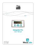
Integrator 110
User Manual
Mesa’s Commitment
As a manufacturer of critical equipment, quality is the highest priority in
our manufacturing process. Mesa commits to providing creative,
innovative thinking and the engineering and scientific expertise needed to
produce gas flow-related products and solutions that are universally
recognized for their superior performance, quality and value.
Bios DryCal technology is the recognized leader in gas flow
measurement, providing the industry’s most reliable products, service and
solutions for professionals in environmental protection, workplace safety,
industrial process control and laboratory calibration.
We strive to provide the closest NIST-traceable, legal defensibility of any
flow calibration equipment manufacturer, and we actively maintain our
NVLAP (NIST) ISO 17025 laboratory accreditation in order to support our
claims and continually improve our quality system and laboratory proficiency. Thank you for purchasing our products. From all of us at Mesa,
best wishes for many years of accurate, defensible primary flow
measurements.
Mesa Laboratories Inc. 10 Park Place Butler, NJ 07405 USA
(973) 492-8400 FAX (973) 492-8270 www.mesalabs.com Symbol “MLAB” on the NASDAQ
2
Table of Contents
Introduction........................................................................................................................................................2
Register Your Product..........................................................................................................................................2
About Your Integrator 110...................................................................................................................................2
Operating Your Integrator 110.............................................................................................................................3
Getting Started.......................................................................................................................................................................3
Features.................................................................................................................................................................................3
Using Your Integrator 110....................................................................................................................................4
Connectivity Diagram..............................................................................................................................................................4
The Main Menu: Three Modes of Operation..............................................................................................................................5
Input & Output Signal Check – Diagnostics...............................................................................................................................5
MFC Control: Operation One....................................................................................................................................................5
Compare MFC and ML: Operation Two......................................................................................................................................6
Compare MFM and ML: Operation Three...................................................................................................................................7
Maintenance and Troubleshooting........................................................................................................................9
Annual Calibration...................................................................................................................................................................9
Sending Your Integrator 110 to Mesa.......................................................................................................................................9
Troubleshooting.................................................................................................................................................................... 10
Shipping.............................................................................................................................................................................. 10
Pin Configuration (25-pin D-Sub)........................................................................................................................11
Make MFC/MFM Cable.......................................................................................................................................12
DB25 Pin Designation............................................................................................................................................................ 13
Integrator 110 Specifications..............................................................................................................................13
Limited Warranty...............................................................................................................................................14
Accuracy
Reliability
Convenience
1
Introduction
Congratulations! You’ve chosen the Mesa Integrator™ 110 command, control and readout device. This powerful tool
integrates Proven Bios DryCal® Technology and a range of systems to make it easier than ever to perform in-house
verifications and multi-setpoint calibrations of your analog mass flow devices.
Before you get started, we recommend taking a few moments to review this manual and familiarize yourself
with your Integrator 110. If at any time you have questions regarding its operation, please contact Mesa through
our Web site (http://drycal.mesalabs.com), or call us at 973.492.8400 to speak with one of our knowledgeable customer support representatives.
Register Your Product
Before we begin, please register your product with Mesa Laboratories, Inc. To complete your registration, log on to our
website at http://drycal.mesalabs.com and complete the registration form. Registration of your new Bios DryCal product
ensures your instruments warranty claim information is properly documented in Mesa’s database, and provides you the
peace of mind that your new calibration equipment is covered under our warranty service plan. Additionally, this registration will allow you to better manage your service and calibration dates through the receipt of timely reminders at 45
and 15 days prior to the recommended calibration date of your instrument.
Mesa recommends annual service and calibration of your Bios DryCal primary gas flow standard as a periodic quality assurance measure, as well as to provide you and your organization with a defensible audit trail of premier quality.
About Your Integrator 110
The Integrator 110 is a microprocessor-based, two-channel device that powers, controls and integrates analog mass
flow controllers (MFC) and mass flow meters (MFM), enabling them to be verified and calibrated by the Mesa Met
Lab® and Definer® Series of primary piston provers, which feature Proven Bios DryCal® Technology. Please note that
these products are referred to within your Integrator’s menu screens as “DryCal”.
One of the Integrator’s channels controls and monitors the gas flow through an MFC, the other channel monitors
the flow through an MFM.
Your Integrator 110 comes with the following:
•
•
•
•
Power Cord
PC Serial Cable
Calibration Certificate (voltage and current)
Manual
2
Operating Your Integrator 110
Getting Started
The Integrator 110 operates from A/C power. To turn on your Integrator 110, plug the power cord into a standard
wall outlet and flip the On/Off switch located on the back of the unit. When turned on, your Integrator 110 displays a
“splash” screen indicating the product name and product revision level.
Navigating through your Integrator 110’s menu screens is easy and intuitive. Simply press one of the four arrows on
the control panel in the desired direction to toggle between menu options: The right arrow advances you forward,
the left moves you backward, the up moves you upward, and the down moves you downward.
To begin a calibration use the navigation features to establish the system parameters relevant to that particular
calibration setpoint.
When entering setpoints and full scale flow rates, use the numbered keypad to enter digits, and then press ENTER
on the keypad to move onto the next available selection. When selecting flow units (such as sccm) and device signals
(such as 5 volts), use the right and left arrows to make your selection. To advance to the next menu screen, press
ENTER on NEXT. This saves your entries and the screen moves to the next screen options.
Each menu screen features NEXT, BACK, EXIT and sometimes DIAG, where NEXT advances you to the next step in
the process; BACK brings you to the previous menu to enable you to make changes or to review your selections; EXIT
brings you first to the splash screen and then to the first menu in the setup process to allow you to reset the parameters; and DIAG allows you to check the device under test parameters (see Input & Output Signal Check – Diagnostics).
Features
Figure 1: Control Panel
Figure 2: Rear Panel
The Integrator 110’s control panel is very simple and features the keypad, menu navigation and illuminated LCD
display. The keypad is comprised of numbers zero through nine and a decimal key, while the menu navigation has
four directional arrows and an ENTER button.
3
The rear panel features the following ports and switches for integrating various components (from left to right):
POWER INPUT. An IEC-320 power connector for A/C power operation with an integral On/Off power switch.
PC. A 9-pin female D-sub connector. Connects your Integrator 110 to your PC.
DRYCAL. A 9-pin female D-sub connector. Connects your Integrator 110 to your Mesa Met Lab® Series primary
piston prover.
AUX. An extra port that’s currently not used, but may serve as an expansion port in the future.
MFM/EXPANSION PORT. A multi-function port. It’s a 25-pin D-sub connector for attaching MFM cables (cables vary
by MFM manufacturer; Mesa offers various cable types for your convenience). It may also be used to “warm up” a
mass flow device while you’re simultaneously calibrating another device via the MFC port. If and when Mesa enables
the manipulation of additional devices, it will also serve as an expansion port.
MFC PORT. A 25-pin D-sub connector for attaching MFC cables (cables vary by MFC manufacturer; Mesa offers various
cable types for your convenience).
VALVE. An extra port that’s currently not used, but may serve as an expansion port in the future.
FAN. A 25mm x 8mm cooling fan (exhaust) with a finger guard for your protection.
RESET SWITCH. A “hard” reset that returns your Integrator 110 to the main menu. Your settings for the current
calibration process will be lost.
PROGRAM LOAD SWITCH. Allows you to “flash” upgrade your Integrator 110’s firmware in order to take advantage of
available upgrades.
Using Your Integrator 110
Connectivity Diagram
Use Figure 3 to familiarize yourself with your Integrator 110’s connectivity options.
Your Integrator 110 is equipped with three serial ports (RS-232). The PC port connects to your PC, the DryCal port
to your Met Lab and Definer Series primary piston prover, and the AUX port is an expansion port for future use as
available. Two D-25 (D-Sub) ports are available for use with MFCs and MFMs. The program load switch enables you to
flash upgrade your Integrator 110.
Figure 3 – Connectivity Diagram
PC
DryCal
Reset
Power Inlet
AUX
Program
Load
MFM
Ventilation Fan
MFC
Valve
4
The Main Menu: Three Modes of Operation
Your Integrator 110’s main menu offers three modes of operation:
Control MFC. Allows you to create an MFC setpoint and read the MFC’s output signal.
Compare MFC and DryCal. With the MFC as the device under test, you can create an MFC setpoint, read the MFC’s
output signal and then compare the output signal to your DryCal’s flow measurements. A deviation percentage is
displayed on your Integrator 110’s screen.
Compare MFM and DryCal. With the MFC as the flow source and the MFM as the device under test, you can create
an MFC setpoint to generate a specific flow rate, read your MFM’s output signal and then compare the output signal
to your DryCal’s flow measurements. A deviation percentage is displayed on your Integrator 110’s screen.
Input & Output Signal Check – Diagnostics
As a quality assurance measure, your Integrator 110 has a diagnostics function that enables you to review the setpoint and/or output signals from your mass flow device. Within certain menu screens (such as MFC Output), Diagnostics may be accessed during any of the three modes of operation by navigating to the “Diag” option, located in the
bottom-right corner of the screen.
The signal levels reflect the MFC’s setpoint and output flow rates, or MFM’s output flow rate.
Control MFC: Operation One
MFC Control describes the mode of operation for controlling an MFC using your Integrator 110.
Gas Supply
MFC
1. Attach the appropriate MFC cable into the MFC and your Integrator 110.
2. Connect your gas supply to the MFC.
3. Turn on your Integrator 110.
4. Once the splash screen ends, select “Control MFC” and press ENTER.
5. At “Input to MFC” select the analog signal, then navigate to “Next” and press ENTER.
6. At “Output from MFC” select the analog signal, then navigate to “Next” and press ENTER.
7.At “Connect MFC” select “Next” and press ENTER to begin “Checking Setup.” Your Integrator 110 will
check the MFC’s connection.
8.Gas flow needs to be turned on for a successful connection, select “continue” to ignore this step.
9.Upon successful setup, input the “MFC Full Scale Flow” value (the rated flow of the MFC) using the keypad,
and press ENTER. Then, arrow down to select the flow units using the right and left arrows, then navigate to
“Next” and press ENTER.
10.Input the “MFC Setpoint” (within the rated specification of the MFC) using the keypad, and press ENTER.
Then, navigate to “Next” and press ENTER.
11.When the display begins flashing, your Integrator 110 is updating the MFC’s output reading against the
MFC’s setpoint value.
12.To change the MFC’s flow, navigate to BACK and press ENTER. Input the new “MFC Setpoint”
and follow Steps 9 through 10 as prompted.
5
Compare MFC and DryCal: Operation Two
Compare MFC and DryCal describes the mode of operation for comparing an MFC to your Met Lab primary
piston prover using your Integrator 110.
Gas Supply
MFC
DryCal
1. Attach the appropriate MFC cable into the MFC and your Integrator 110.
2. Attach the 9-pin cable into your DryCal and your Integrator 110.
3. Connect your gas supply to the MFC, connect the outlet of the MFC to the inlet of the DryCal.
4.Turn on your Integrator 110 and your DryCal. Make sure that your DryCal is set to read in
sccm and the temperature correction matches that of the MFC under test.
5. Once the splash screen ends, select “Compare MFC and DryCal” and press ENTER.
6. At “Input to MFC” select the analog signal, then navigate to “Next” and press ENTER.
7. At “Output from MFC” select the analog signal, then navigate to “Next” and press ENTER.
8.At “Connect MFC and DryCal” select “Next” and press ENTER to begin “Checking Setup.” Your Integrator 110
will check the communication among all systems.
9. Gas flow needs to be turned on for a successful connection, select “continue” to ignore this step.
10. Upon successful setup, at “% Deviation” select the deviation type, then navigate to “Next” and press ENTER.
11.At “MFC Full Scale Flow” (the rated flow of the MFC) input the value using the keypad, and press ENTER.
Then, arrow down to select the flow units using the right and left arrows, then navigate to “Next” and
press ENTER.
12.Input the “MFC Setpoint” (within the rated specification of the MFC) using the keypad, and press ENTER.
Then, navigate to “Next” and press ENTER.
13.When the display begins flashing, your Integrator 110 is updating the MFC’s output reading against the
MFC’s setpoint value, and the DryCal’s flow measurement is recorded and updated. The deviation percentage
between MFC and the DryCal is displayed.
14.To change the MFC’s flow, navigate to BACK and press ENTER. Input the new “MFC Setpoint” and
follow Steps 11 through 12 as prompted.
6
Compare MFM and DryCal: Operation Three
Compare MFM and DryCal describes the mode of operation for controlling flow through an MFM via an MFC or via
an external device (i.e., needle valve, sonic nozzle) using your Integrator 110.
Via an MFC
Gas Supply
MFC
MFM
DryCal
1. Attach the appropriate MFC cable into the MFC and your Integrator 110.
2. Attach the appropriate MFM cable into the MFM and your Integrator 110.
3. Attach the 9-pin cable into your DryCal and your Integrator 110.
4.Connect your gas supply to the MFC, connect the outlet of the MFC to the inlet of the MFM,
connect the outlet of the MFM to the inlet of the DryCal.
5.Turn on your Integrator 110 and your DryCal. Make sure that your DryCal is set to read in sccm
and the temperature correction matches that of the MFC under test.
6. Once the splash screen ends, select “Compare MFM and DryCal” and press ENTER.
7. At “MFM Output Signal” select the analog signal, then navigate to “Next” and press ENTER.
8. At “MFM Flow Source” select “MFC” and press ENTER.
9. At “Input to MFC” select the analog signal, then navigate to “Next” and press ENTER.
10. At “Output from MFC” select the analog signal, then navigate to “Next” and press ENTER.
11.At “Connect MFC and MFM and DryCal” select “Next” and press ENTER to begin “Checking Setup.”
Your Integrator 110 will check the communication among all systems.
12. Gas flow needs to be turned on for a successful connection, select “continue” to ignore this step.
13. Upon successful setup, at “% Deviation” select the deviation type, then navigate to “Next” and press ENTER.
14.At “MFM Full Scale Flow” (the rated flow of the MFM) input the value using the keypad, and press ENTER.
Then, arrow down to select the flow units using the right and left arrows, then navigate to “Next” and
press ENTER.
15.At “MFC Full Scale Flow” (the rated flow of the MFC) input the value using the keypad, and press ENTER.
Then, arrow down to select the flow units using the right and left arrows, then navigate to “Next” and
press ENTER.
16.Input the “MFC Setpoint” (within the rated specification of the MFC) using the keypad, and press ENTER.
Then, navigate to “Next” and press ENTER.
17.When the display begins flashing, your Integrator 110 is updating the MFM’s output reading against the
MFC’s setpoint, and the DryCal’s flow measurement is recorded and updated. The deviation percentage
between MFM and the DryCal is displayed.
18. Press ‘back’ to change the flow to the MFM and repeat Steps 15 through 16 as prompted.
7
Via an External Device
Gas Supply
Ext. Mech
MFM
DryCal
1. Attach the appropriate MFM cable into the MFM and your Integrator 110.
2. Attach the 9-pin cable into your DryCal and your Integrator 110.
3.Connect your gas supply to the external mechanical device, connect the outlet of the external mechanical
device to the inlet of the MFM, connect the outlet of the MFM to the inlet of the DryCal.
4.Turn on your Integrator 110 and your DryCal. Make sure that your DryCal is set to read in sccm and the
temperature correction matches that of the MFC under test.
5. Once the splash screen ends, select “Compare MFM and ML” and press ENTER.
6. At “MFM Output Signal” select the analog signal, then navigate to “Next” and press ENTER.
7. At “MFM Flow Source” select “EXT Mechanical” and press ENTER.
8.At “Connect MFM and DryCal” select “Next” and press ENTER to begin “Checking Setup.” Your Integrator 110
will check the communication among all systems.
9. Gas flow needs to be turned on for a successful connection, select “continue” to ignore this step.
10. Upon successful setup, at “% Deviation” select the deviation type, then navigate to “Next” and press ENTER.
11.At “MFM Full Scale Flow” (the rated flow of the MFM) input the value using the keypad, and press ENTER.
Then, arrow down to select the flow units using the right and left arrows, then navigate to “Next” and
press ENTER.
12.The flow indicated by the DryCal unit is recorded and updated in this step with a percentage deviation between
MFM and DryCal readings.
8
Maintenance and Troubleshooting
Annual Calibration
Your Integrator 110 is a high precision voltage and current measuring device that is used to provide set points and
read voltage and current signals from mass flow devices. As such, your Integrator 110’s voltage and current settings
should be calibrated at least annually by an ISO 17025-accredited calibration laboratory, such as Mesa’s Butler, NJ
site.
Please note that while any ISO 17025–accredited gas flow measurement laboratory may be capable of calibrating
your Integrator 110, Mesa is the only authorized service center for Bios DryCal products. All Integrator 110 service
and calibration is performed in our ISO 17025–accredited laboratory in New Jersey by experienced personnel.
Turnaround time within Mesa’s facility is generally two weeks. For an expedite fee and as available, we will place your
Integrator 110 “next on bench” for 48-hour turnaround. This means that an Integrator 110 received on Monday will
be return-shipped on Wednesday and a Integrator 110 received on Friday will be return-shipped on Tuesday. Although
we cannot guarantee successful expedited turnaround, we will make every effort to accommodate your request.
For a detailed explanation of our service process, expedite option and to obtain current calibration pricing, please
contact us at 973.492.8400 or visit our web site at http://drycal.mesalabs.com.
Sending Your Integrator 110 to Mesa
Please contact Mesa for an RMA (return merchandise authorization) number before sending your Integrator 110 to
our factory for annual calibration or other service. You can get an RMA number through our automated web-based
system at http://drycal.mesalabs.com, by email to [email protected], or by telephone at 973.492.8400.
Sending your Integrator 110 to Mesa without an RMA number may result in return of the instrument without inspection or a substantial delay in service turnaround time.
When requesting your RMA number, provide your Integrator 110 serial number and revision level, as well as your
full contact information. Also, please describe any product issues you may be experiencing. Please keep in mind that
Mesa will not begin evaluation and service of your Integrator 110 until you have accepted and approved, in writing,
our formal RMA quote for service. This protects both you and Mesa during this process and ensures a fair and efficient service experience.
If sending your Integrator 110 for warranty evaluation or repair, please contact Mesa for troubleshooting assistance
prior to shipment to our facility (see Troubleshooting).
9
Troubleshooting
If you should encounter any problems with your Integrator 110, please contact Mesa Customer Service and provide a
detailed description of your situation, including your Integrator 110 serial number, information about the flow source,
the current calibration setup, environmental conditions during the test, the flow point or points that you’re checking
and an explanation of the issue you’re experiencing.
With your help, our technical support team will attempt to resolve the situation over the phone and/or via email.
If we’re unable to do so, we’ll issue you an RMA number for the prompt return of your Integrator 110 for evaluation.
Before contacting Mesa with any problems, please verify the following:
• Is your Integrator 110 plugged into the appropriate power source and turned on?
• Are all of the appropriate cables plugged into the devices under test?
• Are all of the appropriate cables plugged into your Integrator 110?
• Are you using the correct setups (voltage and/or current) for devices you’re operating?
• Is your DryCal Series primary piston prover powered on?
•A
re your DryCal settings correct? For example, standardized flow, standardizing temperature,
Sensor Factors, etc.
• Is your gas supply on?
• Are all the pneumatic connections correct and tight?
Mesa will make every attempt to verify your issue, as we want you to get the most out of your Integrator 110.
However, if you’ve shipped your Integrator 110 to Mesa for an issue that we’re unable to verify – or, if we determine
that the issue is application-related rather than product-related – we reserve the right to charge an evaluation fee
at prevailing labor rates.
Shipping
When shipping your Integrator 110, please ensure that the packaging is adequate to protect the instrument.
Whenever possible, your Integrator 110 should be shipped in its original packaging or within a hard case, such as
a Pelican carrying case (available for purchase from Mesa). We highly recommend using a standard freight carrier
(e.g., FedEx, UPS) that supplies tracking numbers and insuring the product against damage in transit.
Mesa is generally not responsible for freight cost associated with shipments to and from Mesa, except in certain
instances; please contact Mesa for information before initiating a shipment.
Mesa is not responsible for damage that occurs during shipment.
10
Pin Configuration (25-pin D-Sub)
Below is a table for the pin assignments for the MFC and MFM.
(Connector is on the back of the Integrator. Customers may use this to fabricate cables to connect to their MFC/MFMs
or may purchase cables from Mesa Labs)
Pin No.
Description
MFC/MFM Power Connections
1
Power Ground
A.+ 15 VDC Supply Voltage
2
N/C
3
Signal Ground
• Positive, pin 4
• Negative, pin 1
4
+ 15V_1.7A, MFC /MFM Power
5
GND2
6
N/C
7
N/C
8
N/C
C.30 VDC Supply Voltage
9
N/C
10
N/C
• Positive, Pin 5 (jumper pin 4 to pin 23)
• Negative, pin 1
11
N/C
12
Signal Voltage in MFC/MFM
13
N/C
14
N/C
15
Signal Voltage out MFC
16
N/C
17
N/C
18
Signal Current out MFC
19
N/C
20
N/C
21
N/C
22
Signal Current in MFC/MFM
23
-15V_1.7A, MFC/MFM Power
24
N/C
25
N/C
B.– 15 VDC Supply Voltage
• Negative, pin 23
• Positive, pin 1 (jumper pin 1 to pin 5)
Drawing of MFC/MFM Connector on back
of Integrator
25-pin D-Sub
(Female on Integrator 110)
13
1
25
14
N/C = no connection
11
Make a MFC/MFM Cable
Two MFC/MFM cables are supplied to a user with an Integrator 110.
The Integrator 110 side of the cable is connected to a fixed female DB25 pin.
The MFC/MFM side of the cable is left open-ended for the users to configure and connect to their MFC/MFM
connector. This side can be connected to a DB15, DB9, DB25 etc based on the type of MFC/MFM pin connector.
There are a total of nine terminals brought out for the users to configure their own cable.
Figure 4 – MFC/MFM Cable
DB-25 Pin, connects
Open ended MFC/MFM
to the Integrator
side, connects to MFC/MFM
12
DB25 Pin Designation
Configure your MFC/MFM cable as the connection table below.
Description
Wire Color
Special Notes:
1
Power Ground
Black
A.+ 15 VDC Supply Voltage
2
N/C
3
Signal Ground
White
• Positive/+15 V, pin 4
• Negative/ Power ground, pin 1
4
+ 15V_1.7A, MFC /MFM Power
Red
5
GND2
Brown
B.– 15 VDC Supply Voltage
6
N/C
7
N/C
8
N/C
9
N/C
10
N/C
11
N/C
12
Signal Voltage from MFC/MFM
13
N/C
14
N/C
15
Signal Voltage to MFC
16
N/C
17
N/C
18
Signal Current to MFC
19
N/C
20
N/C
21
N/C
22
Signal Current from MFC/MFM
Blue
23
-15V_1.7A, MFC/MFM Power
Purple
24
N/C
25
N/C
Pin No.
• Negative/-15 V,pin 23
•P
ositive/ Power ground, pin 1
(jumper pin 1 to pin 5)
C.30 VDC Supply Voltage
Yellow
Orange
Green
• Positive/30 V, Pin 5 (jumper pin 4 to pin
23)
• Negative, pin 1
The jumpers for – 15 V/ 30 V are not connected at the Integrator side. Make connection
at the MFC/MFM side
D.Signal Voltage from MFC/MFM and Signal
Voltage to MFC are 0-5 VDC or 1-5 VDC
E.Signal Current from MFC/MFM and Signal
Current to MFC are 0–20 miliAmp DC
or 4-20 miliAmp DC
N/C = no connection
Integrator 110 Specifications
Output
Input
Power:
90-264 VAC, 47-53 Hz.
Power Supply:
+/- 15 VDC or 30 VDC
Operating Temperature:
0-50°C
Current:
4-20 ma, 0-20 ma
Storage Temperature:
-20 - 85°C
Resolution:
0.4 micro-amp
Communication Ports:
9-pin D-Sub (RS232)
Uncertainty:
.015% Full Scale
MFC Electrical Connection:
25-pin D-Sub
Voltage:
1-5 V, 0-5 V
MFM Electrical Connection:
25-pin D-Sub
Resolution:
0.1 mVDC
Optional Valve
Electrical Connection:
9-pin D-Sub
Uncertainty:
.015% FS
MFC/MFM:
4-20 ma, 0-20 ma,
1-5 V or 0-5 V
13
Limited Warranty
The Mesa Integrator 110 is warranted to the original end user to be free from defects in materials and workmanship under normal use and service
for a period of one year from the date of purchase as shown on the purchaser’s receipt. If your Integrator 110 was purchased from an authorized
reseller, a copy of an invoice or packing slip showing the date of purchase may be required to obtain warranty service.
The obligation of Mesa Laboratories, Inc. under this warranty shall be limited to repair or replacement (at our option), during the warranty period,
of any part that proves defective in material or workmanship under normal use and service, provided the product is returned to Mesa Laboratories,
Inc., transportation charges prepaid.
Notwithstanding the foregoing, Mesa Laboratories, Inc. shall have no liability to repair or replace any Mesa Laboratories, Inc. product:
1.That has been damaged following sale, including but not limited to damage resulting from improper electrical voltages or currents,
defacement, misuse, abuse, neglect, accident, fire, flood, terrorism, act of God or use in violation of the instructions furnished by Mesa Laboratories, Inc.;
2. When the serial number has been altered or removed; or,
3.That has been repaired, altered or maintained by any person or party other than Mesa Labs’ own service facility or
a Mesa authorized service center, should one be established.
This warranty is in lieu of all other warranties, and all other obligations or liabilities arising as a result of any defect or deficiency of the product,
whether in contract or in tort or otherwise. All other warranties, expressed or implied, including any implied warranties of merchantability and
fitness for a particular purpose, are specifically excluded.
In no event shall Mesa be liable for any special, incidental or consequential damages for breach of this or any other warranty,
express or implied, whatsoever.
Mesa Labs
10 Park Place
Butler, NJ, USA 07405
Phone: 973.492.8400
Toll Free: 800.663.4977
Fax: 973.492.8270
Email: [email protected]
web: www.mesalabs.com
© 2013 Mesa Labs MK01-107 Rev G
14


