1
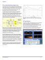
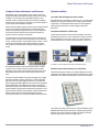
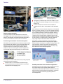
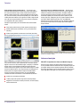
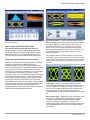
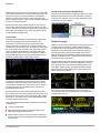
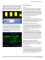
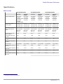
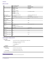
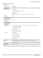
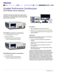
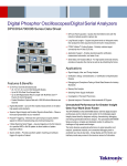
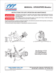
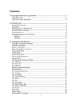
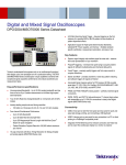
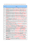
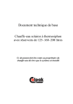
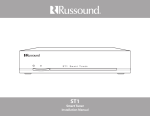
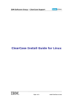
Scalable Performance Oscilloscopes
DPO70000SX Series Datasheet
DPO70000SX provides ultra-high bandwidth real time signal acquisition
and analysis up to 70 GHz analog bandwidth. The patented Asynchronous
Time Interleaving (ATI) architecture provides the lowest noise and highest
fidelity for real time signal acquisition.
Superior signal fidelity and excellent signal-to-noise ratio
Stable and precise multi-channel timing for most accurate analysis
Compact instrument package with flexibility for future expansion and
simple reconfiguration
Low-noise, high fidelity signal acquisition is critical in ultra-bandwidth
applications such as long-haul coherent optical, 400G datacomm and
wideband RF. The flagship DPO77002SX model uses ATI (Asynchronous
Time Interleaving) architecture to achieve 70 GHz and 200 GS/s (5 ps/
Sample) real time acquisition performance. This patented, symmetric
architecture elegantly creates an inherent noise advantage over legacy
bandwidth interleaving methods. The DPO70000SX provides the lowest
noise, highest fidelity and maximum performance for complex optical
modulation analysis, jitter and noise analysis of high speed serial signaling
and frequency, phase and modulation analysis of wideband RF signals.
Introduction
DPO70000SX-series oscilloscopes provide the most accurate real time
performance for ultra-bandwidth applications.
Low noise, 70 GHz real time signal capture using patented ATI
architecture
Compact 5 ¼" (3U) instrument package for the most versatile multichannel systems
Precise, scalable performance using UltraSync multi-unit time
synchronization bus
Highest trigger performance with >25 GHz Edge trigger bandwidth,
unique new Envelope trigger
www.tektronix.com 1
Datasheet
2 www.tektronix.com
Scalable Performance Oscilloscopes
www.tektronix.com 3
Datasheet
ATI architecture delivers lowest noise
Current real time scope solutions for digitizing ultra-high bandwidth signals
distribute signal energy to two digitizing paths then use DSP to reconstruct
the input signal. Unlike legacy schemes, Tektronix' unique ATI architecture
provides a symmetric technique that delivers all signal energy to both
digitizing paths resulting in an inherent noise advantage.
The diagram shows how an input signal enters the ATI ASIC where it is
sampled and alternately delivered to each digitizing subsystem. The
sample clock runs at 75 GHz and effectively folds the spectrum of the input
signal about 37.5 GHz prior to digitizing. Each digitizing path operates at
100 GS/s and the folded spectrum is band limited to <40 GHz to meet
Nyquist criteria. The alternating phase of the sampler has the effect of
inverting signal phase 180° in one digitizing path, which provides significant
benefit in reconstructing the final digitized signal.
DPO77002SX vs. other vendor's 63 GHz model: Baseline noise % of FS vs. mVFS
setting, with trace centered, at 60 GHz BW, maximum sample rate setting (200 GS/s or
160 GS/s)
JNF performance
An all-new master sample clock design which provides the remarkably low
sample clock jitter of 65fsRMS, combined with the very low noise
performance achieved with ATI, allows the DPO77002SX to reach new
levels of jitter noise floor performance. The JNF at 300 mVFS is a mere
123 fsRMS, which even rivals lower bandwidth instruments.
With two copies of the entire signal energy digitized, the signal spectra are
"unfolded" using a DSP equivalent of the sampling process and combined
to reproduce the input signal. Because two copies of the signal are being
combined the process effectively averages them together, reducing random
noise. Phase-inversion introduced by the sampling process causes
intermediate frequency components to directly cancel one another,
simplifying reconstruction and calibration.
Thus, ATI architecture provides an inherent SNR advantage over legacy
digital-bandwidth interleaving techniques. These techniques immediately
split an input signal into upper and lower bands of frequencies. This divides
the power and the upper frequency band must be mixed down prior to
digitizing while the lower band is directly digitized. This asymmetric
approach can make signal reconstruction and calibration more difficult and
lead to errors in pass-band frequency or phase response. The division of
power removes the opportunity to reduce signal noise. ATI alleviates these
issues by using a unique symmetric architecture.
A comparison of baseline noise between the Tektronix DPO77002SX and
another vendor's 63 GHz model, with both instruments set to 60 GHz
bandwidth, demonstrates the effectiveness of ATI at providing the lowest
noise acquisition.
4 www.tektronix.com
The figure shows jitter analysis of 60 GHz sine wave applied to the ATI
input. The result shows a clean eye with random jitter RJ <80 fsRMS.
Scalable Performance Oscilloscopes
Compact ultra-performance oscilloscope
DPO70000SX-series models establish a unique compact oscilloscope
package that enables unprecedented workspace efficiency and mounting
versatility. The SX-series provides a differentiated approach to ultrabandwidth real time acquisition that aligns with user trends toward large
external monitors, higher degrees of automation and increased separation
of data collection and data analysis workspaces.
Stand-alone DPO70000SX compact models provide functionality equivalent
to their bench counterparts (DPO70000DX) at half the height through
addition of external display, keyboard and mouse. SX-series models can
host Advanced Analysis software and be automated using internal or
external control just as their bench counterparts.
The DPO77002SX 70 GHz ATI Performance Oscilloscope provides one
channel at 70 GHz, 200 GS/s acquisition performance or two channels at
33 GHz, 100 GS/s acquisition. The instrument includes a 70 GHz, 1.85 mm
low-noise ATI input channel as well as general purpose TekConnect
2.92 mm inputs for versatile probing and signal conditioning options to
33 GHz.
Optimal usability
Less than half the height of bench models
DPO70000SX-series instruments are contained in a 5 ¼" (3U) package that
optimizes space usage and enables the most versatile range of mounting
configurations. Two DPO70000SX instruments stack in less height than
similar-class bench instruments, yet achieve higher measurement
performance.
Complete standalone oscilloscope
Though compact, SX-series models provide full standalone oscilloscope
functionality and performance. They can directly host Tektronix' Advanced
Analysis applications for tasks such as jitter, noise, optical modulation or
spectral analysis and do not require a separate processor or control unit.
2 x 70 GHz, 4 x 33 GHz configuration with monitor and auxiliary front panel
The DPO73304SX model provides two channels at 33 GHz, 100 GS/s
acquisition or four channels at 23 GHz, 50 GS/s real time acquisition
performance. This model provides acquisition performance similar to the
DPO73304DX bench model, but in the new compact instrument formfactor.
All models in the DPO70000SX-series achieve the highest level of trigger
performance available in real time oscilloscopes, >25 GHz edge trigger
performance and <40 ps glitch trigger performance. An innovative new
Window trigger type enables triggering on the envelope of RF signal bursts
with time-qualification to discriminate envelope width. Industry-leading
pulse-width timer performance enables the most precise discrimination of
specific bit-widths in high speed serial data streams and detection of "runt"
pulses in the midst of pseudo-random signaling. The DPO70000SX-series
Auxiliary Trigger input provides low-jitter edge triggering and uses
TekConnect accessories for a wide variety of signal conditioning solutions.
Familiar scope controls where you want them
The DPO7AFP Auxiliary Front Panel is a valuable usability accessory that
compliments the compact instrument package by enabling users to operate
with familiar controls without requiring access to the front of an instrument.
The Auxiliary Front Panel provides the same control set embedded in DPO/
DSA/MSO/7000/70000 bench instruments as a separately packaged USB
peripheral. This accessory enhances usability even when the instrument
front panel may be obscured due to mounting location.
www.tektronix.com 5
Datasheet
The Trigger bus provides Run-Stop control for all members of a multiunit configuration and enables the trigger source to be from a Master or
Extension unit.
Control & data transfer from Extension units to the Master are
managed with a PCIe, Gen 2, x4 link capable of 2 GB/s data transfer
rate.
Remote desktop operation
As with current bench-model DPO /MSO70000-series instruments,
DPO70000SX models can be operated remotely over a network using
Windows® Remote Desktop. Use the Windows Remote Desktop utility to
access your oscilloscope from across the lab or across the globe.
Precision synchronization for multi-unit systems
DPO70000SX-series instruments include the Tektronix UltraSync multi-unit
time synchronization bus. UltraSync is used to synchronize sample clock,
trigger and run-stop control across multiple units with performance
equivalent to that found in monolithic scopes. UltraSync cables are
available in 1 meter and 2 meter length to maximize configuration and
layout versatility while preserving timing integrity of a multi-unit system.
When operating in a multi-unit instrument configuration, one DPO70000SX
has the role of Master, controlling one or more units operating in Extension
mode. Any DPO70000SX model can operate as a standalone oscilloscope
or serve as Master or Extension in a multi-unit configuration. Roles are
determined by UltraSync cabling and no additional elements are needed.
This allows users to decouple multi-unit configurations at any time and
operate instruments in a standalone fashion without requiring a control unit
or other accessories. Or, standalone units can be easily combined by
simply adding UltraSync cables between Master and Extension.
During startup of a multi-unit configuration a Configuration Manager
application validates Master-Extension cabling and provides graphical
feedback if elements are missing or misconfigured. Following validation, the
system presents the TekScope user interface where waveforms from
Master and Extension units are gathered for display and analysis using
built-in features and Advanced Analysis applications.
The UltraSync bus consists of three elements, each providing an important
element of precise multi-unit operation:
UltraSync includes a 12.5 GHz Sample Clock Reference signal
sourced by the Master and used by each Extension to synchronize
sample placement in the digitizing process.
Scalable performance and versatile configurations
DPO70000SX multi-unit modes enable a variety of extended performance
and increased channel-count configurations. Master-Extension
configurations provide additional input channels synchronized to the same
degree of precision as internal channels and controlled from a single user
interface as an interactive instrument or programming interface in
automated applications.
6 www.tektronix.com
Scalable Performance Oscilloscopes
This scalable approach to performance allows users to purchase
performance suitable for today's requirements, such as four channels of
33 GHz, 100 GS/s acquisition while also having two channels with 70 GHz,
200 GS/s performance suitable for next-generation designs. Subsequently,
two additional units can be added for a total of four channels at 70 GHz,
200 GS/s. Units in this four-unit configuration can be separately deployed
as pairs or standalone units at any time to meet other test demands.
Another important aspect of skew is how the phase relationship between
two channels varies with changing frequency (group delay effects). The
following plot compares the performance of a DPS77004SX 70 GHz twounit system against the performance of another vendor's 63 GHz
frequency-interleaved channels. What you see here is that the UltraSync
two-channel skew performance dramatically surpasses the performance of
a another vendor's single 63 GHz model containing two channels.
The DPO77002SX also offers a unique value proposition in single-channel
70 GHz, 200 GS/s applications such as RF analysis or pulsed laser studies.
In these cases a user can purchase a single unit for 70 GHz channel
performance along with two channels at 33 GHz. Additional units can be
purchased at a later time and combined using UltraSync if higher channel
count is needed.
The following multi-unit configurations are supported:
2 DPO77002SX: 2 Ch @ 70 GHz, 200 GS/s or 4 Ch @ 33 GHz, 100 GS/s
4 DPO77002SX: 4 Ch @ 70 GHz, 200 GS/s or 4 Ch 1 @ 33 GHz, 100 GS/s
2 DPO75902SX: 2 Ch @ 59 GHz, 200 GS/s or 4 Ch @ 33 GHz, 100 GS/s
4 DPO75902SX: 4 Ch @ 59 GHz, 200 GS/s or 4 Ch 1 @ 33 GHz, 100 GS/s
2 DPO75002SX: 2 Ch @ 50 GHz, 200 GS/s or 4 Ch @ 33 GHz, 100 GS/s
Channel skew vs. Frequency comparison between DPO77002SX system and other
vendor's 63 GHz model.
4 DPO75002SX: 4 Ch @ 50 GHz, 200 GS/s or 4 Ch 1 @ 33 GHz, 100 GS/s
2 DPO73304SX: 4 Ch @ 33 GHz, 100 GS/s or 4 Ch 1 @ 23 GHz, 50 GS/s
2 DPO72304SX: 4 Ch @ 23 GHz, 100 GS/s or 4 Ch 1 @ 23 GHz, 50 GS/s
Skew Stability
UltraSync provides outstanding integration and time alignment between
units in a multi-unit stack. Once channels have been deskewed in a multiunit stack, skew is very stable over time and temperature. The specification
for skew stability is ≤250 fsRMS. The following DPO77002SX skew
measurement plot shows that even when including the startup temperature
stabilization period (approximately 1 hour), the pk-pk variation is about
400 fs, and is about 350 fs pk-pk after the 1-hour warm-up period. This plot
also shows exceptional consistency over this 12-hour data collection.
Short signal path
Minimizing input signal path length is especially important when working at
70 GHz ultra-high bandwidth. The compact nature of DPO70000SX creates
more versatile mounting options when co-locating instrument and device
under test (DUT). Options such as the Auxiliary Front Panel and Remote
Desktop connection allow further flexibility by eliminating the need for direct
access to the instrument front panel once connected. As a result, the SXseries enables the broadest range of options when dealing with a variety of
DUT configurations as compared to classic bench instruments.
Input signal path length may be minimized in multi-unit configurations by
inverting one unit of a pair. The low, central location of the 70 GHz ATI
input provides very small input connector spacing when operating units in
this configuration.
Instruments can also be arranged at various angles to suit DUT layout,
such as at right angles for card-and-backplane situation or face-to-face
around a small DUT. Layouts such as this create the shortest input signal
path and maximize SNR. In addition, effects of signal path elements such
as cables and adapters can be characterized and removed using the Serial
Data Link Analysis application to obtain the best analysis results and
insight.
Change in channel-to-channel skew of DPO77002SX system over time.
1
Maximum of 4 channels displayed on-screen. Access to additional channels data available through program interface.
www.tektronix.com 7
Datasheet
Applications
Coherent optical modulation analysis
Tektronix DPO70000SX oscilloscopes are ideal for modulation format
analysis of 400 Gb/s and Terabit-based coherent optical networking
systems. The unique architecture enables scalability to grow instrument
performance by adding channels or more bandwidth; to test 100 G cost
effectively now and expand into 400 G or 1 Terabit later. The DPO70000SX
low profile reduces concerns of signal loss in system connectivity on your
coherent measurements by placing the Optical Receiver as close as
possible to the instrument's input channel.
70 GHz Bandwidth on 4 Channels for 1 Terabit/s systems
Industry-best lowest noise for low EVM
200 GS/s sampling on 4 channels for phase tracking
Compact form factor with scalability for channel & bandwidth
Customizable DSP for unique analysis needs
PAM4 and NRZ datacom measurements
More accurate modulation analysis starts with a lower Error Vector
Magnitude (EVM) floor in the instrument. The DPO70000SX Oscilloscope
utilizes ATI technology to provide the industry's lowest noise floor
supporting these measurements. In addition, the system is achieving four
channels of full 70 GHz Bandwidth at 200 GS/s per channel, providing a
very rich analysis environment. When used in conjunction with the OM4524
Optical Modulation Receiver, optical system research engineers can
customize their DSP analysis and visualization for non-standard modulation
techniques using easy customer-specific implementations with extensive
customizable analysis SW that leverages Matlab™.
8 www.tektronix.com
As datacom networks increase their throughput, the DPO70000SX is ready
to perform standards validation for many of today's 25/28 G industry
standards (see chart below). With 50 GHz and 70 GHz models featuring
the low-noise ATI architecture; the DPO70000SX, combined with DPOJET
Jitter & Noise Analysis and the SDLA Serial Data Link Analysis tools, can
perform accurate de-embedding and eye diagram evaluation on many of
these key standards.
Scalable Performance Oscilloscopes
RF
With its low noise and flat frequency response to 70 GHz, the
DPO70000SX opens opportunities for measurement and analysis of
wideband RF signals.
SignalVu® vector signal analysis – When vector signal analysis of RF or
baseband signals are needed, the optional SignalVu application enables
measurements in multiple domains (frequency, time, phase, modulation)
simultaneously. SignalVu measurements are fully correlated with the
scope's time domain acquisition and triggering. Time domain events, such
as commands to an RF subsystem, can be used as trigger events, while
the subsystem's RF signal can be seen in the frequency domain.
With 400 G networking, new serial data transmission speeds will reach
56 Gb/s per channel, making NRZ signaling techniques ineffective, leading
to bandwidth efficient PAM4 (4 level pulse amplitude modulation). Accurate
PAM4 validation is best conducted using the DPO70000SX Series with its
industry-leading low noise ATI technology to achieve good effective bits
performance on measurement results. For analysis of PAM4, the
DPO70000SX Option PAM4 provides built-in software clock recovery,
multi-level eye diagram plots and unique report tables for effective
measurements as show below.
In addition to spectrum analysis, spectrograms display both frequency and
amplitude changes over time. Time-correlated measurements can be made
across the frequency, phase, amplitude, and modulation domains. This is
ideal for signal analysis that includes frequency hopping, pulse
characteristics, modulation switching, settling time, bandwidth changes,
and intermittent signals.
SignalVu can process RF, I and Q, and differential I and Q signals from any
oscilloscope inputs. Math functions applied by the oscilloscope are also
used by SignalVu allowing users to apply custom filtering prior to vector
signal analysis.
The Microsoft Windows environment makes the use of this multi-domain
analysis even easier with an unlimited number of analysis windows, all
time-correlated, to provide deeper insight into signal behavior. With a user
interface that adapts to your preferences (keyboard, front panel, touch
screen, and mouse), SignalVu is easy to apply for both first-time users and
experienced hands.
Time-correlated, multi-domain view provides a new level of insight into
design or operational problems not possible with conventional analysis
solutions. Here, the hop patterns of a narrowband signal can be observed
using Spectrogram (lower left) and its hop characteristics can be precisely
measured with Frequency vs Time display (upper left). The time and
frequency responses can be observed in the two right-hand views as the
signal hops from one frequency to the next.
Built-in clock recovery for PAM4 and NRZ-based signals up to
140 Gb/s
Fine timing resolution with up to 200 GS/s sampling on each differential
channel
Debug edge timing using 25 GHz hardware trigger system
www.tektronix.com 9
Datasheet
Radar and high frequency-based analysis – The low-noise, high
bandwidth DPO70000SX Series Oscilloscope is ideal for high frequency
FFT-based measurement analysis. When combined with the powerful
SignalVu software analysis option, the DPO70000SX instrument provides
FFT (fast fourier transform) measurement capability up to 70 GHz. With its
scalable instrument architecture, RF engineers can obtain a single channel
unit for RF input-only measurements and grow to multi-unit configurations
for comprehensive RF system validation.
Examples of high-frequency RF measurements with the DPO70000SX
include:
Options tailored for your wideband applications – SignalVu vector
signal analysis software offers options to meet your specific application,
whether it be wideband radar characterization, broadband satellite, or
spectrum management. SignalVu Essentials (Opt. SVE) provides the
fundamental capability for all measurements and is required for pulse
analysis (Opt. SVP), settling time (Opt. SVT), digital modulation analysis
(Opt. SVM), flexible OFDM analysis (Opt. SVO), and AM/FM/PM
Modulation and Audio Measurements (Opt. SVA). Wideband satellite and
point-to-point microwave links can be directly observed with SignalVu
analysis software.
Chirp Linearity measurements on Radar signals (see below figure)
Wireless measurements on IEEE802.11ad e.g. (60.48 GHz carrier
frequency)
Monitor & debug satellite communications over K-Band (20-40 GHz)
General Purpose Digital Modulation Analysis (Opt. SVM) used to demodulating a 16QAM
backhaul link running at 312.5 MS/s.
Advanced analysis
Once low-noise waveform data is captured by the 70 GHz DPO70000SX,
SignalVu can be used to demodulate the signal, and display a constellation
diagram and Error Vector Magnitude (EVM) measurement and other
needed measurements. SignalVu also provides detailed analysis in multiple
domains as additional options, such as pulse analysis and settling time for
Radar systems work, digital modulation analysis and flexible OFDM
analysis for emerging modulation standards, as well as AM/FM/PM
modulation and audio measurements for lower bandwidth requirements.
Industry low-noise enables low EVM floor
70 GHz provides wide dynamic range and accurate chirp linearity
Integrated FFT & Phase Plot creation provides fast, accurate frequency
domain measurements
10 www.tektronix.com
DPOJET Comprehensive Jitter and Noise Analysis
DPOJET provides engineers the highest measurement sensitivity and
accuracy available in real-time instruments. With comprehensive jitter and
eye-diagram analysis and decomposition algorithms DPOJET simplifies
discovering signal integrity concerns and jitter and their related sources in
today's high-speed serial, digital, and communication system designs.
Scalable Performance Oscilloscopes
DPOJET Jitter and Eye Diagram Analysis - Simplify identifying signal integrity issues,
jitter, and their related sources.
Noise analysis with DPOJET (Opt. DJAN)
Jitter essentials, advanced analysis and custom extensions –
DPOJET Essentials is standard on the DPO70000SX Series with the
DPOJET advanced version available as an option. Application-specific
measurement packages are also available that extend DPOJET and
perform the extensive set of tests required by industry standard groups.
SDLA signal path de-embed and custom filters
Acceleration of signaling speeds and shrinking geometries create several
challenges for next generation multi-gigabit designs and test
methodologies. Designs are evolving to address these challenges with
advanced equalization techniques at the transmitter and receiver. Smaller
form factors make signal access more difficult, resulting in non-ideal
probing points. This can lead to loss and reflections on the acquired signal
due to impedance discontinuities that are not present at the ideal
measurement location. The advanced techniques employed by the designs
call for advanced measurement solutions. The challenge begins with the
signal acquisition; capturing a signal through cables, probes and fixtures
distort the signal shape. SDLA Visualizer allows you to de-embed the
effects (reflections, insertion loss, and cross coupling) of the measurement
circuit (cables, probes, and fixtures) from the waveform while taking into
account the transmitter output and receiver input impedance. Deembedding these effects improves the accuracy of measurements and can
make the difference between passing or failing a test.
Signal path equalization – Using the optional Serial Data Link Analysis
Visualizer (SDLA64) application, you can gain further insight into serial data
links with the capability to emulate the serial data channel from its Sparameters, remove reflections, cross- coupling, and loss caused by
fixtures, cables, or probes, and open closed eyes caused by channel
effects using receiver equalization techniques, such as CTLE, DFE, FFE.
IBIS-AMI models for silicon-specific receiver equalization can used to
observe on-chip behavior.
The eye diagrams below illustrate the correlated eye of a signal before a
channel, after a channel, and after equalization. Eye closure due to channel
effects have effectively been removed using SDLA and in this case the eye
widths are within ~3 ps as shown in the eye diagram on the left and right
hand sides.
Custom filters – Create your own filters or use the filters provided
standard with the DPO70000SX Series to enhance your ability to isolate or
remove a component of your signal (noise or specific harmonics of the
signal). These customizable FIR filters can be used to implement signalprocessing techniques, such as removing signal pre-emphasis or
minimizing the effects of fixtures and cables connected to the device under
test.
Built-in analysis system – DPO70000SX includes a wide variety of builtin features for visualizing and measuring signal behaviors. Select from
54 automatic measurements using a graphical palette that logically
organizes measurements into Amplitude, Time, Histogram, and
Communications categories. Gather further insight into your measurement
results with statistical data such as mean, min, max, standard deviation,
and population.
www.tektronix.com 11
Datasheet
Define and apply math expressions to waveform data for on-screen results
in terms that you can use. Access common waveform math functions with
the touch of a button. Or, for advanced applications, create algebraic
expressions consisting of live waveforms, reference waveforms, math
functions, measurement values, scalars, and user-adjustable variables with
an easy-to-use calculator-style editor.
Custom math expressions with MATLAB
Tektronix custom math expressions with MATLAB enable users to create
MATLAB scripts that process live waveform data and return results into
scope math traces. Extensions can also use MATLAB features to create
specialized analysis and visualizations.
With deep acquisition memory, margin testing can be done over many
cycles and long duration trends in the data can be observed. Plus, data
from the oscilloscope can be captured into Microsoft Excel using the unique
Excel toolbar, and formatted into custom reports using the Word toolbar
provided with the DPO70000SX Series.
Counter timer
The high resolution counter/timer is a new optional feature that is made
possible by the new trigger system in the DPO70000SX series
oscilloscopes. This is a precision frequency counter which provides
frequency analysis up to 25 GHz, with up to 13 digits of resolution and
12 digits/second. Using the internal clock, this counter is accurate to better
than 1 ppm. Higher accuracy is possible using a high precision external
clock source. Because this measurement is made through the trigger
system, it measures each and every cycle of the signal on a continuous
basis during the trigger gate time, rather than making measurements on
finite blocks of data through the normal acquisition channel.
Pinpoint® trigger
Whether you're trying to find a problem signal or need to isolate a section of
a complex signal for further analysis, Tektronix Pinpoint® triggering
provides the solution. Pinpoint® triggering allows selection of virtually all
trigger types on both A and B trigger events delivering the full suite of
advanced trigger types for finding sequential trigger events. Pinpoint®
triggers provide trigger reset capabilities that begin the trigger sequence
again after a specified time, state, or transition so that even events in the
most complex signals can be captured.
The DPO70000SX-series provides the highest trigger system performance
available in a real time scope. The figure shows triggering on <50 ps bitwide runt pulses (fails to cross both thresholds within specified time) on
25.78 GBaud (100GbE) signaling. High system bandwidth and extreme
trigger timer precision enable reliable capture of signal aberrations and
efficient isolation of fault conditions.
This feature provides the ability to make highly accurate clock stability
measurements. In the screen capture shown, a deviation of 212 μHz of
source wander is measured on an 8 GHz precision source. In this figure,
the signal generator was set to 8.00000000001 GHz, and the scope
measured precisely that amount.
The timer allows precise measurements between trigger events with a
200 fs resolution, and can include time measurements from an A event to a
B event, where A and B events can be any valid trigger mode (e.g. Glitch,
Runt, Edge, etc). This feature is useful for measuring propagation delays,
or analyzing anomaly occurrence rates.
Three important distinctions between this counter/timer and conventional
counter/timers are:
> 25 GHz analog bandwidth
Wide selection of high bandwidth scope probes available for the
highest signal fidelity connection to the DUT
Ability to view the waveform on-screen to insure the counter/timer is
seeing a valid waveform, and that trigger levels are set appropriately
for the waveform
12 www.tektronix.com
In the next figure, pulse width discrimination is used to isolate pulses
>40 ps and <60 ps wide, showing reliable capture of 50 ps pulses within a
20 Gbps PRBS11 sequence.
Scalable Performance Oscilloscopes
DPO70000SX includes a unique Envelope trigger mode that enables direct
triggering on the envelope of a modulated carrier. Edge, Width and Timeout
trigger types can be applied to a detected envelope to provide stable trigger
on modulated bursts or discriminate bursts of a specific width. Carrier
frequency can range from 500 MHz to 20 GHz to address a broad range of
applications. The figure illustrates triggering on burst of specific width.
Signal acquisition
ATI input
The DPO77002SX 70 GHz ATI input channel uses industry-standard
1.85 mm coaxial connection system specified to 67 GHz, with typical
performance to 70 GHz. The instrument includes a calibration-grade
1.85 mm female-female adapter installed in the ATI input connector (male)
to provide mechanical protection and gender selection. Instruments also
include a static protection wrist strap, torque wrench and a set of backing
wrenches to facilitate proper care and installation of signal path elements,
ensuring optimal measurement performance. The 1.85 mm connection
system is compatible with 2.4 mm (50 GHz) elements.
TekConnect® inputs
DPO70000SX models include the TekConnect signal interconnect system,
offering unparalleled versatility with a wide array of accessory signal access
and conditioning solutions. The TCA-292D TekConnect adapter provides
2.92 mm connection, 50 Ω coaxial environment to 33 GHz.
Visual Trigger further extends the Pinpoint Triggering's capabilities, adding
another level of trigger qualification to find important events in a wide
variety of complex signals. Visual Trigger qualifies Pinpoint triggers by
scanning through all waveform acquisitions and comparing them to onscreen areas (geometric shapes). Up to eight areas can be created using a
mouse or touchscreen, and a variety of shapes (triangles, rectangles,
hexagons, or trapezoids) can be used to specify the desired trigger
behavior. Once shapes are created, they can be edited interactively to
create ideal trigger conditions
Probing and remote-head coaxial input
Often the biggest challenge in debugging a system is getting access to
required signals. Tektronix offers a wide array of probing solutions,
including the P7600 and P7500 TriMode® probing system with bandwidths
that are well matched to the DPO70000SX Series. This extensive probe
offering is compatible with the TekConnect input available on all
DPO70000SX models.
The P7600 and P7500 TriMode® probes allow you to switch among
differential, single-ended, and common-mode measurements without
moving the probe from its connection points. The P7600 series combines
low noise, 33 GHz bandwidth and the convenience of TriMode probing.
Coaxial adapters enable the probe to act like a remote-head differential
input channel for the oscilloscope which effectively doubles the number of
differential signals a single oscilloscope can measure simultaneously.
The P7500 Series offers probes with performance from 4 GHz to 25 GHz
and offers several low-cost solder tips with quick connection features that
allow moving the probe to various solder points fast and easy.
High performance Auxiliary Trigger input
DPO70000SX includes an Auxiliary Trigger input (TekConnect) suitable for
high performance Edge triggering without consuming an acquisition
channel. Aux trigger bandwidth is >10 GHz on the DPO70000SX-series
with <1.5 psRMS jitter.
Channel timing deskew
All DPO70000SX models include differential fast-edge outputs matched to
<1.6 ps on the front panel that provide a convenient source for aligning
channel timing in a coaxial environment. Instruments include accessories to
accomplish channel-to-channel timing deskew using the built-in source.
Additional accessories can be purchased separately to accomplish even
finer time alignment or deskew in a probe-based environment
www.tektronix.com 13
Datasheet
Bench or rack mount
Rack environment
DPO70000SX models are equally suited for bench and rack-mounted use
and complimented with a number of elements to address specific
environments.
The DPO70000SX rack mount is a tray directly attached to the instrument.
The tray occupies 1U rack height in addition to the 3U instrument and
preserves a cooling channel for the unit. The rack mount also provides
heavy-duty carry handles for transporting the instrument outside the rack
environment.
UltraSync cables are available in 1 meter and 2 meter lengths to enable
configuration flexibility. The default 1 meter cable is suitable for typical twoand four-unit configurations with uniformly stacked instruments. The longer
cable enables combinations operating at 90° to one another or face-to-face
around a DUT. Cable length can be mixed in a configuration to suit
application need and time de-skewed as a system to provide precise
channel-to-channel time alignment.
Instrument cases include recesses that align with feet such that stacked
units mechanically engage one another for added stability. This feature also
works in inverted-stacking configurations and mixed stacks that include an
OM4000 Optical Receiver. Models include threaded holes for user-provided
side brackets in cases where specific combinations are to be "locked"
together.
14 www.tektronix.com
The rack-mounting kit allows units to be mounted upright or inverted to
minimize input cable length, just as when stacking on a bench.
The DPO70000SX rack-mount tray can also house a front-mounted Solid
State Drive (SSD) for easy access to instrument mass storage in a rack
environment.
Scalable Performance Oscilloscopes
Specifications 2
Model overview
2
DPO77002SX/DPS77004SX
DPO75902SX/DPS75904SX
DPO75002SX/DPS75004SX
ATI channel
TekConnect
channels
ATI channel
TekConnect
channels
ATI channel
TekConnect
channels
Analog channels/bandwidth
DPO77002SX
1 ch/67 GHz
1 ch/70 GHz (typical)
DPS77004SX
2 ch/67 GHz
2 ch/70 GHz (typical)
DPO77002SX
2 ch/33 GHz
DPS77004SX
4 ch/33 GHz
DPO75902SX
1 ch/59 GHz
DPS75904SX
2 ch/59 GHz
DPO75902SX
2 ch/33 GHz
DPS75904SX
4 ch/33 GHz
DPO75002SX
1 ch/50 GHz
DPS75004SX
2 ch/50 GHz
DPO75002SX
2 ch/33 GHz
DPS75004SX
4 ch/33 GHz
Sample rate per channel
200 GS/s
100 GS/s
200 GS/s
100 GS/s
200 GS/s
100 GS/s
Rise time (typical)
10% to 90%: 5.6 ps
20% to 80%: 4.3 ps
10% to 90%: 13 ps
20% to 80%: 9 ps
10% to 90%: 6.8 ps
20% to 80%: 5.2 ps
10% to 90%: 13 ps
20% to 80%: 9 ps
10% to 90%: 7.8 ps
20% to 80%: 6 ps
10% to 90%: 13 ps
20% to 80%: 9 ps
Vertical Noise (% of full scale),
BWE on, max sample rate
(typical)
0.83% of full scale
0.71% of full scale
0.83% of full scale
0.71% of full scale
0.83% of full scale
0.71% of full scale
0.75% of full scale
@ 0 V offset
(300 mVFS)
0.56% of full scale
@ 0 V offset
(500 mVFS)
0.75% of full scale
@ 0 V offset
(300 mVFS)
0.56% of full scale
@ 0 V offset
(500 mVFS)
0.75% of full scale
@ 0 V offset
(300 mVFS)
0.56% of full scale
@ 0 V offset
(500 mVFS)
Record length, points (each
channel, standard)
62.5 M
62.5 M
62.5 M
62.5 M
62.5 M
62.5 M
Record length (each channel,
Opt. 10XL)
125 M
125 M
125 M
125 M
125 M
125 M
Record length (each channel,
Opt. 20XL)
250 M
250 M
250 M
250 M
250 M
250 M
Record length (each channel,
Opt. 50XL)
1G
1G
1G
1G
1G
1G
Timing resolution
5 ps (200 GS/s)
10 ps (100 GS/s)
5 ps (200 GS/s)
10 ps (100 GS/s)
5 ps (200 GS/s)
10 ps (100 GS/s)
Duration at highest sample rate
(Standard)
313 µs
625 µs
313 µs
625 µs
313 µs
625 µs
Duration at highest sample rate
(Opt. 10XL)
625 µs
1.25 ms
625 µs
1.25 ms
625 µs
1.25 ms
Duration at highest sample rate
(Opt. 20XL)
1.25 ms
2.5 ms
1.25 ms
2.5 ms
1.25 ms
2.5 ms
Duration at highest sample rate
(Opt. 50XL)
5.0 ms
10 ms
5.0 ms
10 ms
5.0 ms
10 ms
All specifications are guaranteed unless noted otherwise.
www.tektronix.com 15
Datasheet
Model overview
DPO73304SX/DPS73308SX
DPO72304SX
TekConnect channels
TekConnect channels
Analog channels/bandwidth
DPO73304SX
2 ch/33GHz, 4 ch/23GHz
DPS73304SX
4 ch/33GHz, 8 ch 3/23GHz
DPO72304SX
4 ch/23GHz
Sample rate per channel
DPO73304SX
2 ch 100 GS/s, 4 ch 50 GS/s
DPS73304SX
4 ch 100 GS/s, 8 ch 3 50 GS/s
2 ch 100 GS/s, 4 ch 50 GS/s
Rise time (typical)
10% to 90%: 13 ps 20% to 80%: 9 ps
10% to 90%: 17 ps 20% to 80%: 13 ps
Vertical Noise (% of full scale),
BWE on, max sample rate
(typical)
0.71% of full scale
0.71% of full scale
0.56% of full scale @ 0V offset (500 mVFS)
0.56% of full scale @ 0 V offset (500 mVFS)
Record length, points (each
channel, standard)
62.5 M
62.5 M
Record length (each channel,
Opt. 10XL)
125 M
125 M
Record length (each channel,
Opt. 20XL)
250 M
250 M
Record length (each channel,
Opt. 50XL)
DPO73304SX
1 G on 2 ch, 500 M on 4 ch
DPS73304SX
1 G on 2 ch each unit, 500 M on 4 ch each unit
1 G on 2 ch, 500 M on 4 ch
Timing resolution
10 ps (100 GS/s)
10 ps (100 GS/s)
Duration at highest sample rate
(Standard)
625 µs
625 µs
Duration at highest sample rate
(Opt. 10XL)
1.25 ms
1.25 ms
Duration at highest sample rate
(Opt. 20XL)
2.5 ms
2.5 ms
Duration at highest sample rate
(Opt. 50XL)
10 ms
10 ms
Vertical system - analog channels
Input coupling
TekConnect channels:
Two modes: DC, 50 ohms to a programmable termination voltage; Ground.
The termination can be connected to a DC voltage:
≤ 1.2 VFS settings: -3.5 V to 3.5 V,
> 1.2 VFS settings: 0.0 V
ATI channel:
DC, 50 Ω.
Input resistance
≤1.2 VFS settings
50 Ω ±3% at 18 to 28 ºC (64 to 82 ºF)
50 Ω ±4% over 5 to 45 ºC (45 to 113 ºF)
>1.2 VFS settings
3
50 Ω ±4.4% over 5 to 45 ºC (45 to 113 ºF)
Maximum of 4 channels displayed on-screen. Additional channels data available through program interface.
16 www.tektronix.com
Scalable Performance Oscilloscopes
Vertical system - analog channels
Sensitivity range
TekConnect channels
62.5 mVFS to 6 VFS
ATI channel
100 mVFS to 300 mVFS.
Maximum input voltage
TekConnect channels:
≤1.2 VFS settings:
±1.5 V relative to the termination bias (30 mA maximum)
±5 V absolute maximum input
>1.2 VFS settings:
±8 V. Limited by maximum Vterm current and the attenuator power rating at maximum temperature.
ATI channel:
±0.75 Vpk
Aux channel:
±5.0 Vpk
Input termination voltage (VTerm)
range, TekConnect channels
≤1.2 VFS settings:
-3.5 V to +3.5 V
>1.2 VFS settings:
0V
Frequency response tolerance
All modes, BWE on, 18 ºC to
28 ºC (typical)
TekConnect channel:
Step settings TekConnect channels: 77.5 mVFS, 151 mVFS, 302 mVFS, 605 mVFS, 1210 mVFS., 1620 mVFS, 3240 mVFS
±0.5 dB from DC to 50% of nominal BW
±1.5 dB from 50% to 80% of nominal BW
All other gain settings:
±1.0 dB from DC to 50% of nominal BW
±2.0 dB from 50% to 80% of nominal BW
ATI channel:
All volts/div settings
±0.5 dB from DC to 20 GHz
±0.75 dB from >20 GHz to 30 GHz
±1.25 dB from >30 GHz to 68.5 GHz
±2 dB from >68.5 GHz to 69.5 GHz
+2 / -3 dB at 70 GHz
Bandwidth limit
Depending on instrument model: 70 GHz to 1 GHz in 1 GHz steps, or 500 MHz; 5 GHz steps above 35 GHz
Hardware-only bandwidth settings at 33 GHz available on non-ATI channels. No hardware-only settings available on ATI channel.
Vertical resolution
8 bits, (11 bits with averaging)
DC gain accuracy
± 2%
www.tektronix.com 17
Datasheet
Vertical system - analog channels
Effective number of bits (typical).
Average value from DC to full
bandwidth of model.
70 GHz ATI Channel
4.6 bits at 250 mV FS, 200GS/s
59 GHz ATI Channel
4.8 bits at 250 mV FS, 200GS/s
50 GHz ATI Channel
5.0 bits at 250 mV FS, 200GS/s
33 GHz TekConnect Channels 5.0 bits at 500 mV FS, 100GS/s
23 GHz TekConnect Channels 5.4 bits at 500 mV FS, 100GS/s
Offset range
TekConnect channels
ATI channel
Full Scale voltage range
Offset range
62.5 mVFS – 1.2 VFS
±3.4 V
>1.2 VFS – 6 VFS
±6 V
Full Scale voltage range
Offset range
100 mVFS – 300 mVFS
±300 mV - (10 div × Volts/div)
Full scale voltage range
Offset accuracy
100 mVFS to 300 mVFS (ATI channel)
62.5 mVFS to 1.2 VFS (TekConnect channels)
±(0.4% | net offset | + 0.2% | net offset – Vterm setting | +
2.5 mV + 1% FS)
>1.2 VFS to 6 VFS (TekConnect channels)
±(0.6% | net offset | + 13.4 mV + 1% FS)
Offset accuracy
Position range
18 www.tektronix.com
± 5 divisions
Scalable Performance Oscilloscopes
Vertical system - analog channels
Channel-to-channel crosstalk
(channel isolation), typical
Input frequency range (up to the rated bandwidth). Assumes two channels with the same scale and bandwidth settings. The limits
apply up to the bandwidth of the particular instrument.
ATI models
Specified channels
Instrument frequency range
Isolation
ATI channels (isolation between any two DC to 70 GHz
[or more] ATI channels in separate units),
requires UltraSync
70 dB
TekConnect channels in an ATI unit
(isolation between channels 1 and 3)
DC to 33 GHz
60 dB
TekConnect channels to ATI channel
(isolation between channels 1 and 3 to
channel 2)
DC to 4 GHz
55 dB
>4 GHz to 10 GHz
45 dB
>10 GHz to 20 GHz
35 dB
>20 GHz to 30 GHz
30 dB
>30 GHz to 33 GHz
27 dB
DC to 3 GHz
55 dB
>3 GHz to 12 GHz
40 dB
>12 GHz to 33 GHz
30 dB
>33 to 70 GHz
60 dB
Specified channels
Instrument frequency range
Isolation
Isolation between channels 1 or 2 and
channels 3 or 4
DC to 33 GHz
60 dB
Isolation between channels 1 and 2, or
channels 3 and 4
DC to 2 GHz
60 dB
>2 to 10 GHz
42 dB
>10 to 20 GHz
35 dB
>20 to 33 GHz
30 dB
ATI channel to TekConnect (non-ATI)
channels (isolation between channel
2 and channels 1 or 3)
TekConnect models (non-ATI)
Horizontal system
Time base accuracy
±0.8 x 10⁻⁶ ±0.3 x 10⁻⁶ aging/year after first year when operated within 23°C ±5°C after 30 minute warm-up.
Typical: ±0.1 x 10⁻⁶ initial accuracy after adjustment.
Time base delay time range
–5.0 ks to 1.0 ks
Sample Clock Jitter (typical)
<5 μs Duration: 65 fsRMS
Trigger jitter (typical)
10 fs using enhanced trigger placement.
www.tektronix.com 19
Datasheet
Horizontal system
Time/Div settings
ATI channel (only sample rate
is 200 GS/s)
Max RT setting: 500 μs/div (with 1G RL, 50XL option)
Min RT setting: 25 ps/div
Max IT setting: 250 μs/div (with 1G RL, 50XL option)
Min IT setting: 500 fs/div
TekConnect channels (at max Max RT setting: 1 ms/div (with 1G RL, 50XL option)
sample rate of 100 GS/s)
Min RT setting: 50 ps/div
4
Max IT setting: 10 μs/div (with 1G RL, 50XL option)
Min IT setting: 500 fs/div
Delay between channels, BWE
(typical)
≤ 500 fs between any two channels within the same box at any gain setting at 25 °C ±5 °C prior to any user adjustment. Manual
adjustment available with 10 fs minimum resolution. Derate linearly to ≤ 3 ps at 5 °C and 45 °C.
Channel skew stability, UltraSync
(typical)
≤ 250 fsRMS between any two channels between instruments at any gain setting at 25 °C ±5 °C. Derate linearly to ≤ 3 ps at 5 °C
and 45 °C.
Channel-to-Channel deskew range ±75 ns
Acquisition system
Acquisition modes
Sample
Acquires and displays sampled values
Average
From 2 to 10,000 waveforms can be included in an average waveform
Envelope
From 1 to 2×10⁹ waveforms included in min-max envelope
Hi-Res
Real-time boxcar averaging reduces random noise and increases resolution
Peak detect
Capture and display narrow glitches at all real-time sampling rates. Glitch widths: 1 ns at ≤125 MS/s; 1/sample rate at ≥250 MS/s
FastAcq® (TekConnect
channels only)
FastAcq® optimizes the instrument for analysis of dynamic signals and capture of infrequent events, capturing
>300,000 waveforms per second on all TekConnect channels simultaneously, standalone configuration only
FastFrame™
Acquisition memory divided into segments; maximum trigger rate >310,000 waveforms per second. Time of arrival recorded with
each event. Frame finder tool helps to visually identify transients. TekConnect channels only, standalone configuration only
Roll mode
Scrolls sequential waveform points across the display in a right-to-left rolling motion. Works at sample rates up to 10 MS/s with a
maximum record length of 40 MS. TekConnect channels only, standalone configuration only
Waveform database
Accumulates waveform data providing a three-dimensional array of amplitude, time, and counts. TekConnect channels only,
standalone configuration only
Pinpoint® Trigger system
Trigger sensitivity (typical)
4
Internal DC coupled
A-Event trigger, B-Event trigger
≤ 5%FS from DC to 50 MHz
≤ 7.5%FS at 5 GHz
≤ 10%FS at 10 GHz
≤ 15%FS at 15 GHz
≤ 35%FS at 20 GHz
≤ 50%FS at 25 GHz
Aux input 50 Ω (external
trigger)
Auxiliary input
100 mVpp from DC to 1 GHz
175 mVpp at 4 GHz
225 mVpp at 8 GHz
325 mVpp at 10 GHz
800 mVpp at 12 GHz
Sample rate on TekConnect channels can be varied down to 3.125 samples/second, resulting in a max RT setting of 6.55 Ms/div, with a record length of 205 M (requires 250 M or higher RL, 20XL option)
20 www.tektronix.com
Scalable Performance Oscilloscopes
Pinpoint® Trigger system
Edge trigger sensitivity, non-DCcoupled modes (typical)
All sources, positive or negative edge, for vertical scale settings ≥10 mV/div and ≤1 V/div
Trigger Coupling
Sensitivity
NOISE REJ
15%FS from DC to 50 MHz
22.5% at 5 GHz
30%FS at 10 GHz
45%FS at 15 GHz
100%FS at 20 GHz
AC
Same as DC-coupled limits for frequencies > 100 Hz,
attenuates signals <100 Hz
HF REJ
Same as DC-coupled limits for frequencies < 20 kHz,
attenuates signals > 20 kHz
LF REJ
Same as DC-coupled limits for frequencies > 200 kHz,
attenuates signals < 200 kHz
RF
Minimum hysteresis / High sensitivity
A TRIG TekConnect
2.5% FS from DC to 50 MHz
2.5% FS at 5 GHz
2.5% FS at 10 GHz
5% FS at 15 GHz
7.5% FS at 20 GHz
12.5% FS at 25 GHz
B TRIG TekConnect
2.5% FS from DC to 50 MHz
2.5% FS at 5 GHz
2.5% FS at 10 GHz
5% FS at 15 GHz
7.5% FS at 20 GHz
20% FS at 25 GHz
A TRIG ATI
2.5% FS from DC to 50 MHz
2.5% FS at 5 GHz
2.5% FS at 10 GHz
5% FS at 15 GHz
10% FS at 20 GHz
23.5% FS at 25 GHz
B TRIG ATI
2.5% FS from DC to 50 MHz
2.5% FS at 5 GHz
2.5% FS at 10 GHz
5% FS at 15 GHz
10% FS at 20 GHz
22.5% FS at 25 GHz
www.tektronix.com 21
Datasheet
Pinpoint® Trigger system
A-Event and delayed B-Event
trigger types
Standalone instrument
DPO73304SX
DPO72304SX
DPO77002SX
DPO75902SX
DPO75002SX
Trigger type
TekConnect channel
ATI channel
TekConnect channel
Edge
X
X
X
Glitch
X
X
X
Width
X
X
X
Runt
X
X
X
Window
X
X
X
Timeout
X
X
X
Period/Frequency
X
X
X
Envelope
X
X
X
Transition
X
X
X
Logic Pattern
X
X
Setup/Hold
X
X
Low speed serial
X
Logic state
X
Multi-unit configuration
DPO73304SX
DPO72304SX
DPO77002SX
DPO75902SX
DPO75002SX
Trigger type
TekConnect channel
ATI channel
TekConnect channel
Edge
X
X
X
Glitch
X
X
X
Width
X
X
X
X
X
Main trigger modes
Auto, Normal, and Single
Trigger sequences
Main, Delayed by Time, Delayed by Events, Reset by Time, Reset by State, Reset by Transition. All sequences can include a
separate horizontal delay after the trigger event to position the acquisition window in time
Trigger coupling
DC, AC (attenuates <100 Hz)
HF Rej (attenuates >20 kHz)
LF Rej (attenuates <200 kHz)
Noise Reject (reduces sensitivity)
RF coupling (increases trigger sensitivity and bandwidth at the highest operating frequencies)
Variable A-Event trigger holdoff
range
250 ns to 12 s + random holdoff
Trigger level or threshold range
22 www.tektronix.com
Trigger Source
Range
Ch1, 2, 3, or 4
Full scale
Auxiliary input
±3.65 V
Line
0 V, Not settable
Scalable Performance Oscilloscopes
Pinpoint® Trigger system
Enhanced triggering
Enhanced triggering corrects the difference in timing between the trigger path and the acquired data path (supports all Pinpoint
trigger types on both A- and B-Events except pattern trigger); Default On (user-selectable); Not available in FastAcq mode.
Line trigger
Trigger on power line signal. Level fixed at 0 V.
Visual Trigger
Requires Option VET
Max number of areas
8
Area shapes
Rectangle, Triangle, Trapezoid, Hexagon, user defined shapes (can have >40 vertices)
Compatibility
Visual Trigger qualification is compatible with all trigger types and all trigger sequences
Trigger types
Trigger type
Description
Edge
Positive or negative slope on any channel or front-panel auxiliary input. Coupling
includes DC, AC, noise reject, HF reject, LF reject, and RF coupling.
Frequency/Period
Trigger on event that crosses threshold twice with same slope within or outside of
selectable time limits. Slope may be positive, negative or either.
Glitch
Trigger on or reject glitches of positive, negative, or either polarity. Minimum glitch
width is 40 ps (typical) with rearm time of 50 ps (<5 ns interval), 75 ps above 5 ns.
Pattern
Trigger when pattern goes false or stays true for specified period of time. Pattern
(AND, OR, NAND, NOR) specified for four input channels.
Runt
Trigger on a pulse that crosses one threshold but fails to cross a second threshold
before crossing the first again. Event can be time- or logic-qualified. Minimum runt
width is 40 ps (typical) with rearm time of 50 ps
Setup/Hold
Trigger on violations of both setup time and hold time between clock and data
present on any two input channels.
State
Any logical pattern of channels (1, 2, 3) clocked by edge on channel 4. Trigger on
rising or falling clock edge.
Timeout
Trigger on an event which remains high, low, or either, for a specified time period.
Selectable from 300 ps.
Transition
Trigger on pulse edge rates that are faster or slower than specified. Slope may be
positive, negative, or either.
Width
Trigger on width of positive or negative pulse either within or out of selectable time
limits (down to 40 ps).
Window
Trigger on an event that enters or exits a window defined by two user-adjustable
thresholds. Event can be time or logic qualified.
Visual Trigger
Trigger when the Visual Trigger expression is satisfied.
Envelope
Qualification applied to Edge, Glitch, Width or Runt trigger such that trigger type is
performed on the detected envelope of a modulated carrier. Carrier frequency
250 MHz to 15 GHz. Minimum burst width <20 ns, maximum gap between bursts
<20 ns.
Trigger mode
Description
Trigger Delay by Events
1 to 2 billion events.
Trigger Delay by Time
3.2 ns to 3 million seconds.
B-Event Scan
B-Event Scan is an A to B trigger sequence that will trigger and capture burst
event data of interest as defined in the B-Event Scan setup menu. Captured bits
can be scanned in a sequential or randomized fashion, and alternatively the
trigger can toggle between two successive B trigger events. Eye diagrams can be
constructed with burst data acquired as a result of scanning B-Event.
Trigger modes
Trigger modes
www.tektronix.com 23
Datasheet
Waveform analysis
Search and Mark Events
Search and Mark Events
Search for edges, glitches, or pulses of specified width. Any events found matching the search criteria are marked and placed in
the Event table. The search can use positive/negative slopes or both on any channels.
When an event of interest is found, other similar events can be found using "Mark All Trigger Events in Record" in the Pinpoint
trigger control windows.
The Event table summarizes all found events. All events are time stamped in reference to trigger position. Users can choose to
stop acquisitions when an event is found.
Waveform measurements
Waveform measurements
Automatic measurements
54, of which 8 can be displayed on-screen at any one time; measurement statistics, user-definable reference levels, measurement
within gates isolating the specific occurrence within an acquisition to measure
The DPOJET Jitter and Eye Analysis application offers additional automated and advanced measurements such as jitter.
Amplitude related
Amplitude, High, Low, Maximum, Minimum, Peak-to-Peak, Mean, Cycle Mean, RMS, Cycle RMS, Positive Overshoot, Negative
Overshoot
Time related
Rise Time, Fall Time, Positive Width, Negative Width, Positive Duty Cycle, Negative Duty Cycle, Period, Frequency, Delay
Combination
Area, Cycle Area, Phase, Burst Width
Histogram related
Waveform Count, Hits in Box, Peak Hits, Median, Maximum, Minimum, Peak-to-Peak, Mean (μ), Standard Deviation (sigma),
μ +1sigma, μ +2sigma, μ +3sigma
Waveform processing/math
Algebraic expressions
Define extensive algebraic expressions including Waveforms, Scalars, User-adjustable Variables, and Results of Parametric
Measurements e.g. (Integral (CH1 ‒ Mean(CH1)) × 1.414 × VAR1)
Arithmetic
Add, Subtract, Multiply, Divide Waveforms and Scalars
Filtering function
User-definable filters. Users specify a file containing the coefficients of the filter. Several example filter files are provided
Frequency domain functions
Spectral Magnitude and Phase, Real and Imaginary Spectra
Mask function
Generates a Waveform Database pixel map from a sample waveform. Sample count can be defined
Math functions
Average, Invert, Integrate, Differentiate, Square Root, Exponential, Log 10, Log e, Abs, Ceiling, Floor, Min, Max, Sin, Cos, Tan,
ASin, ACos, ATan, Sinh, Cosh, Tanh
Relational
Boolean result of comparison >, <, ≥, ≤, ==, !=
Vertical units
Magnitude: Linear, dB, dBm Phase: Degrees, radians, group delay IRE and mV units
Window functions
Rectangular, Hamming, Hanning, Kaiser-Bessel, Blackman-Harris, Gaussian, Flattop2, Tek Exponential
Customized Functions using
Math Plug-in Interface
An interface is provided to allow users to create their own custom math functions in MATLAB or Visual Studio
Display system
Color palettes
Normal, Green, Gray, Temperature, Spectral, and User-defined
Format
YT, XY, XYZ
Display resolution
1024 horizontal × 768 vertical pixels (XGA)
Display type
6.5 in. liquid-crystal active-matrix color display with capacitive touch screen
Horizontal divisions
10
Vertical divisions
10
Waveform styles
Vectors, Dots, Variable Persistance, Infinite Persistance
24 www.tektronix.com
Scalable Performance Oscilloscopes
Computer system and peripherals
Operating system
Microsoft Windows 7 Ultimate - 64 bit OS
CPU
INTEL CORE I7-4970S, 3.9 GHz, QUAD CORE
System memory
32 GB
Solid state drive
Removable, ≥900 GB capacity
Mouse
Optical wheel mouse, USB interface
Keyboard
USB interface
Input-output ports
Auxiliary trigger input
characteristics and range
50 Ω, ±5 V (DC plus peak AC)
Auxiliary output logic polarity and
functionality
Default output is A trigger low true (a negative edge when the A trigger event occurs). You can also program the output to A trigger
high true, B trigger low or high true, disabled, force high, and force low.
Fast Edge output step amplitude
and offset
1200 mV differential into a 100 Ω load with a -300 mV common mode.
External reference input frequency 10 MHz, 100 MHz, 12.5 GHz
(typical)
The instrument scans for either 10 MHz or 100 MHz. 12.5 GHz supported on separate SMA input.
12.5 GHz Clock In
1.3 Vp-p (6 dBm)
B, C, D 12.5 GHz Clock Out
(UltraSync)
1.3 Vp-p (6 dBm)
Internal reference output voltage
(typical)
10 MHz Vout pk-pk
> 800 mV peak-peak into 50 Ω
> 1.6 V peak-peak into 1 MΩ (internally AC coupled).
Input and output ports
DVI-D Video port
A female Digital Visual Interface (DVI-D) compatible port
VGA port
A female Video Graphics Array (VGA) compatible port
DisplayPort
Two connectors (primary, secondary) provide digital display interfaces
PCIe
PCIe ports to configure multi-instrument systems
Trigger
UltraSync trigger bus
Keyboard and Mouse ports
PS-2 compatible, instrument must be powered down to make connection
LAN ports
Two RJ-45 connectors (LAN1, LAN2), support 10BASE-T, 100BASE-TX, and Gigabit Ethernet
External audio ports
External audio jacks for microphone input and line output
USB ports
Four front panel USB 2.0 connectors
Four rear panel USB 3.0/USB 2.0 connectors
One rear panel USB device connector
www.tektronix.com 25
Datasheet
Data storage specifications
Nonvolatile memory retention time >20 years
(typical)
Solid state drive
Waveforms and setups are stored on the solid state drive.
Solid state drive is a ≥900 GB solid state drive (removable).
Power source
Power consumption
<980 W, single instrument, maximum
≤780 W, single unit (typical)
Source voltage and frequency
100 V to 240 VRMS, 50/60 Hz
115 V ±10%, 400 Hz
CAT II
Mechanical specifications
Dimensions
DPO70000SX models
157 mm (6.0 in) height
452 mm (17.8 in) width
553 mm (21.8 in) depth
DPO70000SX models,
Rackmount configuration
177 mm (7.0 in) height
440 mm (19.75 in) width
523 mm (20.6 in) depth (from rack mounting ear to back of instrument)
Weight
DPO70000SX models
19 kg (42 lbs) oscilloscope only
Cooling
Required clearances
Fan-forced air circulation with no air filter
Top
0 mm (0 in)
Bottom
6.35 mm (0.25 in) minimum or 0 mm (0 in) when standing on
feet, flip stands down
Left side
76 mm (3 in)
Right side
76 mm (3 in)
Rear
0 mm (0 in) on rear feet
Environmental specifications
Temperature
Operating
+5 °C to +45 °C
Nonoperating
-20 °C to +60 °C
26 www.tektronix.com
Scalable Performance Oscilloscopes
Environmental specifications
Humidity
Operating
8% to 80% relative humidity at up to +32 °C (+90 °F)
5% to 45% relative humidity above +32 °C (+90 °F) up to +45 °C (+113 °F), noncondensing, and is limited by a maximum wetbulb temperature of +29.4 °C (+85 °F) (derates relative humidity to 32% at +45 °C (+113 °F)
Nonoperating
5% to 95% relative humidity at up to +30 °C (+86 °F),
5% to 45% relative humidity above +30 °C (+86 °F), up to +60 °C (+140 °F), noncondensing, and is limited by a maximum wetbulb temperature of +29.4 °C (+85 °F) (derates relative humidity to 11% at +60 °C (+140 °F))
Altitude
Operating
Up to 3,000 meters
Nonoperating
Up to 12,000 meters
United States Government Baseline Testing
United States Government
Configuration Baseline (USGCB)
Testing
Tektronix has tested the DPO70000SX Series oscilloscopes for compatibility with the security configuration for Information
Technology products specified in the USGCB settings for Windows 7 and Internet Explorer
Regulatory
Regulatory
Electromagnetic compatibility
2004/108/EC; EN 61326-2-1
Certifications
UL 61010-1, CSA 61010-1-04, LVD 2006/95/EC, EN61010-1, IEC 61010-1
www.tektronix.com 27
Datasheet
Ordering information
Models
DPO77002SX
70 GHz ATI Performance Oscilloscope
DPO75902SX
59 GHz ATI Performance Oscilloscope
DPO75002SX
50 GHz ATI Performance Oscilloscope
DPO73304SX
33 GHz Digital Phosphor Oscilloscope
DPO72304SX
23 GHz Digital Phosphor Oscilloscope
Systems
The following DPS systems provide single-nomenclature ordering convenience for 2 instruments and a 1 meter UltraSync cable. The same options may be applied to these
systems as with base models and the option will be included on both instruments. Both component instruments will have the same options associated with the system
nomenclature when operating standalone.
DPS77004SX
70 GHz ATI Performance Oscilloscope System: 2 x 70 GHz, 200 GS/s or 4 x 33 GHz, 100 GS/s
DPS75904SX
59 GHz ATI Performance Oscilloscope System: 2 x 59 GHz, 200 GS/s or 4 x 33 GHz, 100 GS/s
DPS75004SX
50 GHz ATI Performance Oscilloscope System: 2 x 50 GHz, 200 GS/s or 4 x 33 GHz, 100 GS/s
DPS73308SX
33 GHz Digital Phosphor Oscilloscope System: 4 x 33 GHz, 100 GS/s or 8 x 23 GHz , 50 GS/s
Standard accessories
ATI channel accessories
Accessory
Tektronix part number
Deskew adapter (1.85M to 2.92F)
103-0488-00
ATI connector saver (1.85 mm)
103-0474-00
ATI protective cap
016-2101-00
Torque wrench
067-2787-00
Backing wrench
003-1942-00
Instrument accessories
Accessory
Tektronix part number
User manual -- depends on language option
071-3357-xx
Front protective cover
200-5337-00
PCIe Host Port protective plug
200-5344-00
2nd ethernet port plug
200-5389-00
50 Ω term on Fast Edge (2X)
015-1022-01
TCA-292D (5X) (3X on ATI instruments)
090-0044-00
Windows compatible keyboard
119-7275-xx
Windows compatible mouse
119-7054-xx
Static protection wrist strap
006-3415-05
Deskew cable (M2.92 to M2.92)
174-6793-00
Accessories pouch
016-2045-00
28 www.tektronix.com
Scalable Performance Oscilloscopes
Accessory
Tektronix part number
Best Practices manual
071-2989-04
ROHS info
071-2185-04
Calibration certification
001-1179-00
Cal cert envelope
006-8018-01
Power cord
Warranty
One-year warranty covering all parts and labor.
Instrument options
Record length options
Opt. 10XL
125 MS/Ch
Opt. 20XL
250 MS/Ch
Opt. 50XL
500 MS/Ch on 4 channels, 1 G/Ch on 2 channels
Trigger and limit test options
Option
Description
Opt. VET
Visual trigger
Opt. ASM
Advanced Event Search and Mark
Opt. LT
Waveform limit testing
Advanced analysis options
Option
Description
Opt DJA
Jitter and Eye Analysis Tools - Advanced (DPOJET)
Opt DJAN
DPOJET Noise, Jitter and Eye Analysis Tools (requires DJA)
Opt SDLA64
Serial Data Link Analysis Visualizer
Opt. VET
Visual Trigger
Opt. LT
Waveform Limit Testing
Opt. PAM4
PAM4 Transmitter Analysis Software
Spectral and modulation analysis
Option
Description
Opt. SVE
SignalVu® Essentials - Vector Signal Anallysis Software
Opt. SVA
AM/FM/PM Audio Signal Analysis (Requires Opt. SVE)
Opt. SVM
General Putpose Modulation Analysis (Requires Opt. SVE
Opt. SVO
Flexible OFDM Analysis (Requires Opt. SVE)
Opt. SVP
Advanced Signal Analysis (including pulse measurements) (Requires Opt. SVE)
Opt. SVT
Frequency and Phase Settling Time Measurements (Requires Opt. SVE)
Opt. SV23
WLAN802.11a/b/g/j/p measurement application (requires Opt. SVE)
Opt. SV24
WLAN 802.11n measurement application (requires Opt SV23)
Opt. SV25
WLAN 802.11ac measurement application (requires Opt SV24)
www.tektronix.com 29
Datasheet
Option
Description
Opt. SV27
SignalVu Bluetooth Basic LE TX SIG measurements
Opt. SV28
SignalVu LTE Downlink RF measurements (requires Opt. SVE)
Storage options
Option
Description
Opt. SSD
Additional Removable Disk - Solid State Drive
Floating license options
Floating licenses offer an alternative method to manage your Tektronix asset. Floating licenses allow license-key enabled options to be easily moved among all your MSO/
DPO70000, DPO7000, and MSO/DPO5000 Series oscilloscopes. Floating licenses are available for the license-key enabled options listed below.
Check www.tektronix.com/products/oscilloscopes/floating-licenses for additional information about floating license options.
Option
Description
DPOFL-XL010
Extended record length - 125 M Samples/Ch
DPOFL-XL020
Extended record length - 250 M Samples/Ch
DPOFL-XL050
Extended record length - 500 M Samples/Ch
DPOFL-DJA
Jitter and Eye Analysis Tools - Advanced (DPOJET)
DPOFL-DJAN
DPOJET Noise, Jitter and Eye Analysis Tools
DPOFL-SDLA64
Serial Data Link Analysis Visualizer
DPOFL-VET
Visual Trigger
DPOFL-LT
Waveform Limit Testing
DPOFL-SVE
SignalVu® Essentials - Vector Signal Analysis Software
DPOFL-SVA
AM/FM/PM Audio Signal Analysis (Requires Opt. SVE)
DPOFL-SVM
General Purpose Modulation Analysis (Requires Opt. SVE)
DPOFL-SVO
Flexible OFDM Analysis (Requires Opt. SVE)
DPOFL-SVP
Advanced Signal Analysis (including pulse measurements) (Requires Opt. SVE)
DPOFL-SVT
Frequency and Phase Settling Time Measurements (Requires Opt. SVE)
DPOFL-SV23
WLAN 802.11a/b/g/j/p measurement application (requires Opt. SVE)
DPOFL-SV24
WLAN 802.11n measurement application (requires Opt. SV23)
DPOFL-SV25
WLAN 802.11ac measurement application (requires Opt. SV24)
DPOFL-SV27
SignalVu Bluetooth Basic LE TX SIG measurements
DPOFL-SV28
SignalVu LTE Downlink RF measurements (requires Opt. SVE)
Upgrade options
The DPO70000SX Series instruments can be easily upgraded after initial time of purchase. To upgrade an existing DPO70000SX, order DPO-UP and an option listed below.
For example, DPO-UP DJAN.
Memory upgrades for DPO70000SX Series
XL510
Standard Configuration to Option 10XL Configuration
XL520
Standard Configuration to Option 20XL Configuration
XL550
Standard Configuration to Option 50XL Configuration
XL1020
Option 10XL Configuration to Option 20XL Configuration
XL1050
Option 10XL Configuration to Option 50XL Configuration
XL2050
Option 20XL Configuration to Option 50XL Configuration
30 www.tektronix.com
Scalable Performance Oscilloscopes
Trigger and search upgrades for DPO70000SX Series
VETU
Visual Trigger
LT
Waveform Limit Testing
Advanced analysis upgrades for DPO70000SX Series
DJA
Jitter and Eye Analysis Tools - Advanced (DPOJET)
DJAN
DPOJET Noise, Jitter and Eye Analysis Tools (Requires DJA)
SDLA64
Serial Data Link Analysis Visualizer
Spectral and modulation analysis upgrades for DPO70000SX Series
Option
Description
SVEU
SignalVu® Essentials - Vector Signal Anallysis Software
SVA
AM/FM/PM Audio Signal Analysis (Requires Opt. SVE, SVEH, or SVEU)
SVM
General Putpose Modulation Analysis (Requires Opt. SVE, SVEH, or SVEU)
SVO
Flexible OFDM Analysis (Requires Opt. SVE, SVEH, or SVEU)
SVP
Advanced Pulsed Signal Analysis including Measurements (Requires Opt. SVE, SVEH, or SVEU)
SVT
Freqauency and Phase Settling Time Measurements (Requires Opt. SVE, SVEH, or SVEU)
SV23
WLAN802.11a/b/g/j/p measurement application (Requires Opt. SVE, SVEH, or SVEU)
SV24
WLAN 802.11n measurement application (requires Opt SV23)
SV25
WLAN 802.11ac measurement application (requires Opt SV24)
SV27
SignalVu Bluetooth Basic LE TX SIG measurements
SV28
SignalVu LTE Downlink RF measurements (requires Opt. SVE)
Other upgrades for DPO70000SX Series
IF
Upgrade Installation Service
SSD
Spare Solid State Drive
Investment protection options
As signals get faster and new standards are developed, your investment in an DPO70000SX Series instrument can evolve with your needs. You can upgrade the bandwidth of
the unit you own today. You can take advantage of DPO70000SX series performance improvements by upgrading your existing unit to a new series. Contact your local
Tektronix representative to discuss the full range of options available to ensure your DPO70000SX series oscilloscope has the tools you need for your next project.
Power plug options
Opt. A0
North America power plug (115 V, 60 Hz)
Opt. A1
Universal Euro power plug (220 V, 50 Hz)
Opt. A2
United Kingdom power plug (240 V, 50 Hz)
Opt. A3
Australia power plug (240 V, 50 Hz)
Opt. A5
Switzerland power plug (220 V, 50 Hz)
Opt. A6
Japan power plug (100 V, 50/60 Hz)
Opt. A10
China power plug (50 Hz)
Opt. A11
India power plug (50 Hz)
www.tektronix.com 31
Datasheet
Opt. A12
Brazil power plug (60 Hz)
Opt. A99
No power cord
Service options
Opt. C3
Calibration Service 3 Years
Opt. C5
Calibration Service 5 Years
Opt. D1
Calibration Data Report
Opt. D3
Calibration Data Report 3 Years (with Opt. C3)
Opt. D5
Calibration Data Report 5 Years (with Opt. C5)
Opt. G3
Complete Care 3 Years (includes loaner, scheduled calibration, and more)
Opt. G5
Complete Care 5 Years (includes loaner, scheduled calibration, and more)
Opt. IF
Upgrade Installation Service
Opt. R3
Repair Service 3 Years (including warranty)
Opt. R5
Repair Service 5 Years (including warranty)
Recommended accessories
Probes
P7633
33 GHz Low Noise TriMode® Probe
P7630
30 GHz Low Noise TriMode® Probe
P7625
25 GHz Low Noise TriMode® Probe
P7520A
25 GHz TriMode® probe
P7313SMA
13 GHz TriMode® differential SMA probe
P6251
DC to 1 GHz, 42 V, differential probe (requires TCA-BNC adapter)
TCPA300/TCPA400 Series
Current measurement systems
P5200/P5205/P5210
High-voltage differential probes
067-2431-xx
Probe Deskew Fixture for SMA or solder-down connections (up to 30 GHz)
067-0484-xx
Analog Probe Calibration and Deskew Fixture (4 GHz)
067-1586-xx
Analog Probe Deskew Fixture (>4 GHz)
067-1686-xx
Power Deskew Fixture
Adapters
TCA-1MEG
TekConnect® high-impedance buffer amplifier. Includes P6139A passive probe
TCA-292D
TekConnect® to 2.92 mm adapter (33 GHz bandwidth)
TCA-BNC
TekConnect® to BNC adapter
TCA-N
TekConnect® to N adapter
TCA-VPI50
50 Ω TekVPI to TekConnect adapter
TCA75
8 GHz precision TekConnect® 75 Ω to 50 Ω adapter with 75 Ω BNC input connector
32 www.tektronix.com
Scalable Performance Oscilloscopes
Other
016-2095-xx
Rackmount Kit
016-2102-xx
SSD mounting kit (front of instrument rackmount tray)
077-0076-xx
Service Manual, pdf on hard drive
016-2104-00
Transit Case (carbon fiber)
K4000
Oscilloscope Cart
DPO7AFP
Auxiliary Front Panel
DPO7USYNC 1M
1 meter UltraSync cable
DPO7USYNC 2M
2 meter UltraSync cable
www.tektronix.com 33
Datasheet
The DPO70000SX Series offers the highest performance in Tektronix' Real Time performance oscilloscope portfolio.
Tektronix is registered to ISO 9001 and ISO 14001 by SRI Quality System Registrar.
Product(s) complies with IEEE Standard 488.1-1987, RS-232-C, and with Tektronix Standard Codes and Formats.
Product Area Assessed: The planning, design/development and manufacture of electronic Test and Measurement instruments.
34 www.tektronix.com
Scalable Performance Oscilloscopes
www.tektronix.com 35
Datasheet
ASEAN / Australasia (65) 6356 3900
Belgium 00800 2255 4835*
Central East Europe and the Baltics +41 52 675 3777
Finland +41 52 675 3777
Hong Kong 400 820 5835
Japan 81 (3) 6714 3010
Middle East, Asia, and North Africa +41 52 675 3777
People's Republic of China 400 820 5835
Republic of Korea +822 6917 5084, 822 6917 5080
Spain 00800 2255 4835*
Taiwan 886 (2) 2656 6688
Austria 00800 2255 4835*
Brazil +55 (11) 3759 7627
Central Europe & Greece +41 52 675 3777
France 00800 2255 4835*
India 000 800 650 1835
Luxembourg +41 52 675 3777
The Netherlands 00800 2255 4835*
Poland +41 52 675 3777
Russia & CIS +7 (495) 6647564
Sweden 00800 2255 4835*
United Kingdom & Ireland 00800 2255 4835*
Balkans, Israel, South Africa and other ISE Countries +41 52 675 3777
Canada 1 800 833 9200
Denmark +45 80 88 1401
Germany 00800 2255 4835*
Italy 00800 2255 4835*
Mexico, Central/South America & Caribbean 52 (55) 56 04 50 90
Norway 800 16098
Portugal 80 08 12370
South Africa +41 52 675 3777
Switzerland 00800 2255 4835*
USA 1 800 833 9200
* European toll-free number. If not accessible, call: +41 52 675 3777
For Further Information. Tektronix maintains a comprehensive, constantly expanding collection of application notes, technical briefs and other resources to help engineers working on the cutting edge of technology. Please visit www.tektronix.com.
Copyright © Tektronix, Inc. All rights reserved. Tektronix products are covered by U.S. and foreign patents, issued and pending. Information in this publication supersedes that in all previously published material. Specification and
price change privileges reserved. TEKTRONIX and TEK are registered trademarks of Tektronix, Inc. All other trade names referenced are the service marks, trademarks, or registered trademarks of their respective companies.
29 Sep 2015
www.tektronix.com
55W-30662-6