1
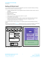
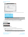
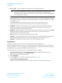
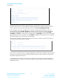
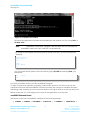
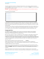
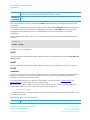
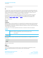
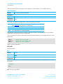
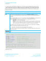
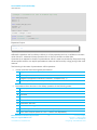
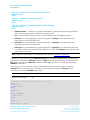
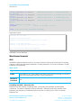
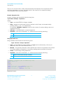
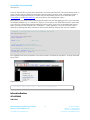
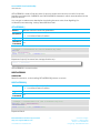
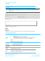
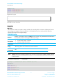
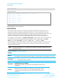
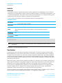
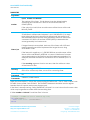
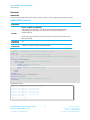
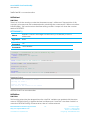
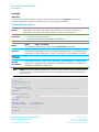
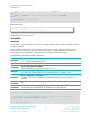
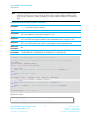
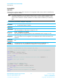
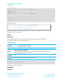
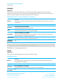
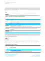
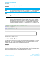
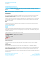
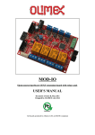
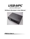
smart BASIC Core Functionality User Manual need to take care that non-standard formatting characters are not incorporated into your smartBASIC application. Config – Configuration window. Used to set up various parameters within UWTerminal. About – Information window that displays when you start UWTerminal. It contains command line arguments and information that can facilitate the creation of a shortcut to the application and launch the emulator directly into the terminal screen. The four LED-type indicators below the tabs display the status of the RS-232 control lines that are inputs to the PC. The colors are red, green, or white. White signifies that the serial port is not open. Note: According to RS-232 convention, these are inverted from the logic levels at the GPIO pin outputs on the module. A 0v on the appropriate pin at the module signifies an asserted state CTS – Clear to Send. Green indicates that the module is ready to receive data. DSR – Data Set Ready. Typically connected to the DTR output of a peripheral. DCD – Data Carrier Detect. RI – Ring Indicate. If the module is operating correctly and there is no radio activity, then CTS should be asserted (green), while DSR, DCD, and RI are deasserted (red). Again note that if all four are white (Figure 6), it means that the serial port of the PC has not been opened and the button labelled OpenPort can be used to open the port. Figure 6: White lights Note: At the time of this manual being written, the DSR line on the BL600 DevKit is connected to the SIO25 signal on the module which has to be configured as an output in a smart BASIC application so that it drives the PC’s DSR line. The DCD line (input on a PC) is connected to SIO29 and should be configured as an output in an application and finally the RI line (again an input on a PC) is connected to SIO30. Please request a schematic of the BL600 development kit to ensure that these SIO lines on the modules are correct. Figure 7: Control options Next to the indicators are a number of control options (Figure 7) which can be used to set the signals that appear on inputs to the module. Embedded Wireless Solutions Support Center: http://ews-support.lairdtech.com www.lairdtech.com/bluetooth 17 Laird Technologies Americas: +1-800-492-2320 Europe: +44-1628-858-940 Hong Kong: +852-2268-6567 x026