1
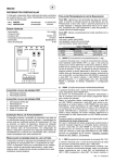
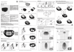
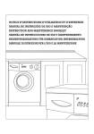
Automatic Bollard
English
AUTOMATIC BOLLARD
ASSEMBLY AND OPERATING MANUAL
MPIE10
400/600/800
Please read the manual very
carefully before installation
V 1.3
R 07/2013
Assembly manual of MPIE10 400/600/800
Automatic Bollard
English
A) Warning to the user and/or installer
1) CAUTION: It is important to your safety that these instructions are followed. The
installation or misuse of this product may cause personal injuries or material damages.
2) Keep these instructions in a safe place for future reference.
3) This product was designed and produced stricly for the use indicated in this manual.
Any other use other than the ones expressly indicated may damage the product and/or
be a source of danger, invalidating the warranty.
4) STATEUROP is not liable for the incorrect use of this product, or another use other
than the one for which it was designed.
5) STATEUROP is not liable if the safety standards were not taken into account when
installing the equipment to be automated, or for any deformation that may occur to it.
6) Before the installation, turn off the power supply.
7) STATEUROP is not liable for the safety and proper installation of the product when
are used components that are not sold by itself.
8) Do not make any changes to the motor components and/or accessories.
9) The installer should inform the customer how to operate the product in emergencies
and provide him with a manual of use.
10) Keep the remote control out of reach of children, preventing the bollard to opperate
accidentally.
11) The custommer shall not, in any circunstances, attempt to repair or tune the
bollard. For this purpose, he must call a qualified technician.
12) Connect the bollard to a 230V power supply, with ground wire.
13) The equipment is determined for outdoor use.
CONFORMITY:
The firm STATEUROP declares, the automatic bollard MPIE10 follows the european norms and directives:
2006/95/CE-Low voltage electrical equipment;
89/336/CEE-Electromagnetic compatibility.
EN 60335-1, EN 55014-1, EN 55014-2, EN 61000-3-2, EN 61000-3-3
The firm STATEUROP declares, the control board MC11 follows the directive
95/05/EC (R&TTE)
Page 01
Assembly manual of MPIE10 400/600/800
Automatic Bollard
English
B) Technical Specifications
1) Motor Specifications:
Model
Input
Power
Intensity
Thermical Protection
Temperature
WING400/600/800
24 VDC
60 W
1.2 - 4A
120ºC
>-20ºC; <+50ºC
2) Control Box Specifications:
Model
Input
Fuse
Output
Temperature
Rising / Falling Time
Automatic closing delay
MC11
AC230V, 50Hz
10 A
12 V DC / 250 mA / 24V DC
>-10ºC; <+55ºC
5 / 8 / 12 seg *
0 - 99 seg
*with soft start/stop
3) Mechanical Specifications:
Mobile piece
Covers
Fitted material
INOX 2.5 mm
Anti-Slip Stainless Steel 4mm
PVC 10 mm
3) Physical Specifications:
204 mm
Diameter
Course
370 / 570 / 785 mm
Top flange
400 mm
Fitted material
Weight capacity when closed
Weight
320 x 320 x 870 / 320 x 320 x 1080 / 320 x 320 x 1280 (mm)
20.000 Kg
35 /40 /45 Kg
Page 02
Assembly manual of MPIE10 400/600/800
Automatic Bollard
English
C) Underground Bollard Installation
C
Cover
Earth
Cement
150mm
B
Sand
PVC cylinder
Power cable
Solid base (in cement) to
support MPIE10
50mm
10º
Protective conduit
for cable passage
A
Sewer
Figure 1: Bollard scheme
CAUTION:
1. IMPORTANT! Place the sewer with a minimum declination of 10º. A
2. Put sand around the bollard, for better accommodation. B
3. The cement must be made with sand. C
4. The control box must be installed in a place near the bollard, at a minimum height of 20cm
from the ground.
5. If the distance from the control box to the bollard MP400/600/800 is bigger than 10 meters,
use a 2.25mm power cable.
Page 03
Assembly manual of MPIE10 400/600/800
Automatic Bollard
English
C) Underground Bollard Installation
In order to install the bollard, you can dismount the cover, making the process much easier. To do
that, you must remove the 6 screws furthest from the center, marked at red in Fig.2.
Next, remove the cover as shown in Fig.3 and place the bollard in the hole (Fig. 5).
Note that no waste or other objects fall into the inside of the bollard protecting the space using a
piece of cloth, paper or other material serving as a seal between the stainless steel tube and the
PVC pipe (Fig.6) . After placing the bollard in the hole and finishing the pavement around it,
remove the material used for sealing and place the cover (Fig.3) in the bollard, fixing it with the six
screws removed early in the process.
The bollard and it’s cover must be aligned as shown in Fig.4.
The installation can be made without following these steps, however, it becomes more complex
and harder, so, it’s advised to follow the steps described above.
Figure 2: Cover
Figure 3: Removing Cover
Figure 5: Bollard installed
Figure 6: Seal the bollard
Figure 4: Bollard’s alignment
Important
Don’t touch the screws marked at green - Fig.2
Page 04
MPI10/ 400: 870mm
MPI10/ 600: 1080mm
MPI10/ 800: 1280mm
MPI10/ 400: 920mm
MPI10/ 600: 1130mm
MPI10/ 800: 1330mm
MPI10/ 400: 370mm
MPI10/ 600: 570mm
MPI10/ 800: 785mm
Assembly manual of MPIE10 400/600/800
Automatic Bollard
English
D) Dimensions
250mm
Page 05
Assembly manual of MPIE10 400/600/800
Automatic Bollard
English
E) Electronic and Control
Control Box Specifications
�
�
�
�
�
�
�
�
�
Input (transformer): 230 VAC
Output (transformer): 24VAC
Fuse: 10 A - 24V / 1 A - 220V
Battery: 12V 1,2 Ah
Codification: 433 MHz Rolling Code
Receiver output: 12 VDC - 250 mA
Temperature: -10°C / + 55 °C
Protection: IP54
Motor speed: 2800 RPM
Programming the Remote Controller:
The remote controller as already been programmed at the factory, but in case of a reset is done,
it’s necessary to program it again. To do so, follow the next steps:
Press the SEL button as many times as needed untill the LED CODE starts blinking. After it,
press the button desired in the remote controller and the LED CODE will remain alight
confirming the reception of the code (proceed the same way for other controllers).
Programming the Bollard:
The bollard as already been programmed at the factory, but for several reasons unrelated to us
it may be necessary to program it again. To program the opening and closing of the bollard be
sure to proceed the following way:
- With the bollard opened (down) press the SEL button as many times as needed untill the LED
AUTO PGM starts blinking, and then press the SET button and wait for the bollard to do two
complete maneuvres (opening and closing), or in other words, untill the LED AUTO PGM stops
blinking.
Release the SET button.
The programming process is now complete.
Transformer
Battery
(The battery only should be connected
after all the installation process is
completed)
Terminal
220-240V
FUSE - 1 A
Potentiometers
Buttons
Connection
terminals
Page 06
Assembly manual of MPIE10 400/600/800
Automatic Bollard
English
E) Electronic and Control
OBSERVATION:
The tuning of the power/velocity has already been programmed at the factory, so as the
value of the sensibility. The bollard after each maneuvre should turn itself off after 2 or 3
seconds, but in case this doen’s happen you’ll have to adjust the sensibility potenciomenter
in the + direction (right).
In case that the maneuvre isn’t completed you’ll have to adjust the same potenciometer a bit
to the left side.
In the end you should repeat the bollard programming process.
Power / Velocity
Right maximum
Sensibility
Middle of the course
Reset of the Control Board (memory cleaning)
In order to perform a general cleaning to the control board’s memory and start a new
programming process, you should press the SEL and SET buttons at the same time untill
all the LEDs of the board light up.
The reset is complete and you may now program the control board.
- To get additional information about the control box and other functions (ex: Photocells),
you should consult your reseller.
Page 07
Assembly manual of MPIE10 400/600/800
Automatic Bollard
English
E)
E) Unlocking
Electrónica e
y control:
controle:
Unlocking the bollard in case of an emergency, power outage or
malfunction.
Slot to make the release
Rotate the key in clockwise direction
IMPORTANT
- After unlocking, the MPIE10 400/600/800 will descend automatically.
- In case of power outage, the bollard is prevented by a battery that has enough power to
make one maneuvre (open or close). You shall not use the bollard anymore untill there is a
power supply at 230V because the battery was designed for emergencies only.
In case you use the bollard more than 1 time powered only by the battery, it may not have
enough energy and an incomplete maneuvre may occur.
- In case of malfuncion of the equipment, you shall call a qualified technician.
Page 08
Assembly manual of MPIE10 400/600/800
Automatic Bollard
English
IMPORTANT
This cable can’t be buried in
direct contact with the soil.
ATTENTION!
A protective conduit must be used
for underground cable passage.
Page 09
M
MÓDULO
LEDs
230/12VAC 50/60Hz 120w MAX
230/24VAC 50/60Hz 120w MAX
(PT) Transformador / (DE) Transformator
(ES) Transformador / (EN) Transformer
(FR) Transformateur / (IT) Transformatore
(PT) Quando motor roda no sentido contrário, troque o fio preto com o castanho
(DE) Motorlaufrichtung ändern durch Tauschen des schwarzen mit dem braunen Kabel
(ES) El motor gira en la dirección equivocada - Cambie los cables negro con marrón
(EN) Motor turning in wrong direction - Swap the black wires with brown wire
(FR) Le moteur tourne dans le mauvais sens - Remplancer les fils marron avec fils noir
(IT) Motore ruota nella direzione sbagliata - Cambiare i fili nero con marrone
Aviso / Hinweis / Aviso / Notice / Avis / Avviso
MPIE10
LEDs RGB
(PT) Esquema de Ligação - MC11 (RGB Led’s + MSC50)
(DE) Verbindungsschema - MC11 (RGB Led’s + MSC50)
(ES) Esquema de enlace - MC11 (RGB Led’s + MSC50)
(EN) Link Scheme - MC11 (RGB Led’s + MSC50)
(FR) Schéme de connexion - MC11 (RGB Led’s + MSC50)
(IT) Schema di collegamento - MC11 (RGB Led’s + MSC50)
2
3
4
5
6
CN1
7
230VAC
+12V-
+ 12V - + +
-
12/20 V BATT S.P. LAMP
1
FUSE
A2
A1
(DE) RELAIS
(ES) RELÉ
(EN) RELAY
(FR) RELAIS
(IT) RELÈ
(PT)RELÉ
14
11
MOT. 2
9 10 11
MOT. 1
8
FUSE
2
+
3
- +v
SERR.
1
4
6
7
8
PUL PED
FA2 FC2
RX
CN1
2
CN2
ANTENNA
2
VR1
SEL
SET
3
4
5
LIGHT SENSOR
24 0 12
1
FA2 FC2
LIGHT MONO TEMP. I.CMD
MSC50
BL DS FA1 FC1
9 10 11 12 13 14 15 16 17 18
230V
1
SET
BL DS FA1 FC1
SEL
SENSIBILITÁ
FORZA/VELOCITÁ
T. RIT. ANTE
T. PAUSA
T. MOT. PED.
T. MOT.
CODE PED.
CODE
AUTO PGM
TIPO MOTORE
VR2
VR1
L.SPIA PUL PED
5
+12V -
CN2
MC11