1
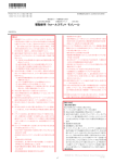
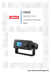
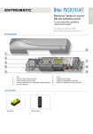
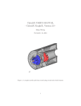
EXIT
Motion Radar Sensor is a digital uni or bidirectional
motion sensor for trouble-free opening of all types of
automatic doors (sliding, swinging, folding, revolving,
speed-doors, overhead doors, etc...), for pedestrian
and civil applications.
It can be adapted to every application without further
accessories and can be controlled by an infrared
remote controller. Mounting height up to 4m (13.12ft)
also available in uni- or bidirectional mode to detect
motion towards or away from the device. Like most of
other microwave detectors, equipped with planar flat
antenna, Carlo Gavazzi Radar activates automatic
doors utilizing doppler shift effect for detecting
movements.
14
.
ft 76
R A D S e ri e s
After installation from the front side, insert the screwdriver in the provided slot.
Fix firmly radar
sensor to the wall.
Avoid the presence
of moving objects
in radar sensing
field.
Not install panels or
metallic surfaces
close to the device.
Not install radar
on direct exposure
of rain.
S10
4.5
m
11
.4
8
EXIT
3.5
14
.
ft 76
EXIT
2.5
2
20
8.
EXIT
S8
RAD 01 To obtain wide pattern install the planar antenna in vertical mode, while to obtain narrow pattern
install the planar antenna in horizontal mode. Carefully remove the fixing tie clip with a screwdriver
3.5orientation mode of planar antenna.
and change the
11
.4
8
EXIT
M ot i on R a d a r S e n s o r
4.
9
To adjust the type of the2.5
sensing field and pattern, verify the following instructions:
Remove cover from behind, before installation.
Automation Components
1.5
4.5
m
4
CARLO GAVAZZI
Installation Tips
8.
20
2
1.5
S5
Detection Area Shape modifying instructions
4.
9
Cover Removing
0.5
Not install radar
close to fluorescent
lamp.
Drilling Plan mm (inches)
1
1.6
4
3.2
8
4.9
2
6.5
6
8.2
40
230
9.8
(1.575”)
(0.905”)
4 Minimum
ft
Clearance
Ceiling
2
100 (3.937”)
Inside View
2.0
20
S10
2.5
S8
3.0
S10
m
1.5
2.5
3.5
4.5
m
5
1.6
4
3.2
8
4.9
2
6.5
6
8.2
0
9.8
4
ft
CAUTION!
Power off the radar before removing the planar antenna.
The radar is an electrostatic sensitive device: proceed with caution to remove the planar antenna,
don’t wear synthetic clothes or rubber sole shoes.
To install radar is necessary only a screwdriver and drill.
3.0 2.5 2.0 1.5 1.0 0.5 0 0.5 1.0 1.5 2.0 2.5 3.0 m
Sensing field adjustment
according to Sensitivity setting and mounting Height
0.5
1.
64
64
1.
0.5
9
1.
6
92
4.
S5
8.
4.5
m
S4
S6
S8
3
1.5
11
.4
8
S10
S2
1.0
3.
14
.
ft 76
9.
8. 6. 4. 3. 1.
8
20 56 92 28 64
ft 4
3.5
Ceiling mounting.
0.5
S1
4
RAD 02 To obtain narrow pattern L3 or L4.
6.5
6
8.2
0
9.8
4
ft
84
81.2.64
0
63.5.28
6
4
4.9.92
2
36.2.56
8
18.6.20
4
9.8
04
1.6ft
4
3.2
8
4.9
2
9.8
4
8.2
0
6.5
6
4.9
2
3.2
8
1.6
4
9. 0
1.
64
4.
92
8.
20
8
4.5
m
2.5
11
.4
3.5
3.0 2.5 2.0 1.5 1.0 0.5 0 0.5 1.0 1.5 2.0 2.5 3.0 m
Electrical Connections
S8
Wall mounting.
1.5
14
.
ft 76
92
4.
8.
20
Mounting Instructions
2.5
RAD 01 To obtain wide pattern L1 install
the planar antenna in vertical mode.
RAD 01 To obtain narrow pattern L2 install
the planar antenna in horizontal mode.
0.5
13
(0.511”)
S5
9.8
4
8.2
0
6.5
6
4.9
2
3.2
8
1.6
4
0
© Copyright – Carlo Gavazzi - All rights reserved
This manual accompanies our equipment for use by the end users.
The technical instructions and illustrations contained in this manual are to be treated as confidential and no part
may be reproduced without the prior written permission of Carlo Gavazzi
Service engineers and end users may not divulge the information contained herein or use this manual for
purposes other than those strictly connected with correct use of the equipment.
Specifications are subject to change without notice. Pictures are just an example.
1.
64
FCC warnings
This device complies with Part 15 of the FCC Rules.
Operation is subject to the following two conditions:
1) this device may not cause harmful interference, and
2) this device must accept any interference received,
including interference that may cause undesired
operation.
S1
1.5
8
In operation: No modifications!
As long as the unit is in operation: do not modify the
installation! The same applies also to the secondary
side.
• The unit must not be opened except appropriately
trained personnel!
• Do not introduce any object into the unit!
• Keep away from fire and water!
3.0 2.5 2.0 1.5 1.0 0.5 03.0 0.5
2.5 1.0
2.0 1.5
1.5 2.0
1.0 2.5
0.5 3.00m0.5 1.0 1.5 2.0 2.5 3.0 m
Ø 8 (5/16”)
Cable inlet
0.5
11
.4
Before start of operation ensure appropriate
installation
Warning! Improper installation / operation impair
safety and result in operational difficulties or complete
failure of the unit.
The unit must be installed and put into service
appropriately by qualified personnel. Compliance with
the relevant regulations must be ensured.
3.0 2.5 2.0 1.5 1.0 0.5 0 0.5 1.0 1.5 2.0 2.5 3.0 m
With stranded wires: all strands must be secured in
the terminal blocks (potential danger of short circuit).
14
.
ft 76
Disconnect system from supply network
Before any installation, maintenance or modification
work:
Disconnect your system from the supply network.
Ensure that cannot be re-connected inadvertently!
Ø 3 (1/8”)
Ø 3 (1/8”)
L6
0
Read Instructions!
Before working with this unit, read these instructions
carefully and completely. Make sure that you have
understood all the information!
L5
9.8
4
8.2
0
6.5
6
4.9
2
3.2
8
1.6
4
0
L4
1.6
4
3.2
8
4.9
2
6.5
6
8.2
0
9.8
4
ft
L3
9.8
4
8.2
0
6.5
6
4.9
2
3.2
8
1.6
4
SafetyL1Notes L2
S1
S1
The sensing field area size (lobo) depends on the sensitivity parameter setting and the radar mounting height.
92
4.
1.5
2.0
2.5
S10
h = 2.2m
h = 7.22ft
3.0
m
9.8
4
8.2
0
6.5
6
4.9
2
3.2
8
1.6
4
9.80
4
81.26
04
63.52
68
4.
92
36.25
86
18.62
40
9.80
4
1.f6t
4
3.2
8
4.9
2
6.5
6
8.2
0
9.8
4
ft
9.
0.5
1.5
2.5
3.5
4.5
m
L5
L6
S1
0.5
6. 4. 3. 1.
92 28 64
5
ft 6
S4
S6
S8
3.
L6 L4
6. 4. 3. 1.
5
92 28 64
ft 6
S2
2.5 1.0
2.0 1.5
1.5 2.0
1.0 2.5
0.5 3.00m0.5 1.0 1.5 2.0 2.5 3.0 m
3.0 2.5 2.0 1.5 1.0 0.5 03.0 0.5
L5 L3
1.
64
4.5
0.5
m
1.0
L4 L2
92
Lateral angle rotation -15°
L3 L1
4.
4.5
m
L2
3.0 2.5 2.0 1.5 1.0 0.5 0 0.5 1.0 1.5 2.0 2.5 3.0 m
20
S10
3.5
8.
L1
Detection area vs Sensitivity value (vertical angle 15°).
S8
S10
6.5
6
8.2
0
9.8
4
ft
8
S8
3.5
2.5
9.8
4
8.2
0
6.5
6
4.9
2
3.2
8
1.6
4
0
1.6
4
3.2
8
4.9
2
8.
20
2.5
11
.4
8
Planar
Antenna
RAD 02 Uni & Bidirectional Model
S5
Detection area vs Sensitivity value (vertical angle 45°); vertical mount mode.
14
.
ft 76
Push Button
INC (+)
1.5
RAD 01 Bidirectional Model
S5
11
.4
20
8.
8
11
.4
Main Connector
Relay NO contact
Relay NC contact
Relay Common
Supply Voltage
12 to 24 VAC/DC
12 to 24 VAC/DC
14
.
ft 76
Push Button
DEC (-)
1.5
9.
8. 6. 4. 3. 11.4
8
20 56 92 28 6.47
ft 6
ft 4
Green LED
92
IR Receiver
4.
Red LED
S5
S4
1.0
S10
1.5
2.0
S6
m
0.5
1.0
1.5
2.0
m
h = 2.2m
h = 7.22ft
S8
S10
Caution:
Power on the radar by Class2 or LVE transformer.
Do not power on the radar until all primary and secondary wiring is completed.
Detection area vs Sensitivity value (vertical angle 45°); horizontal mount mode.
Sensing Field adjustment
Detection area vs Sensitivity value (vertical angle 45°).
Adjust the lateral position to obtain the desired lateral angle sensing field.
9
L6
4.
92
1.5
8.
20
2.5
3.5
4.5
m
4
1.
6
0.5
11
.4
8
2.5
3.0
14
.
ft 76
1.5
64
1.
0.5
4.
92
1.5
1.6
4
3.2
8
4.9
2
6.5
6
8.2
0
9.8
4
ft
9.8
4
8.2
0
6.5
6
4.9
2
3.2
8
1.6
4
0
L5
3.0 2.5 2.0 1.5 1.0 0.5 0 0.5 1.0 1.5 2.0 2.5 3.0 m
8.
20
0
1.6
4
3.2
8
4.9
2
6.5
6
8.2
0
9.8
4
ft
9.8
4
8.2
0
6.5
6
4.9
2
3.2
8
1.6
4
64
L6 L4
S4
2.5
S1
S5
1.5
2.0
m
S10
S1
S5
S10
0.5
14
.
ft 76
S9
S10
1.6
4
3.2
8
4.9
2
6.5
6
8.2
0
9.8
4
ft
3.5
3.0 2.5 2.0 1.5 1.0 0.5 0 0.5 1.0 1.5 2.0 2.5 3.0 m
3.0 2.5 2.0 1.5 1.0 0.5 0 0.5 1.0 1.5 2.0 2.5 3.0 m
4.5
0.5
m
1.0
S8
9.8
4
8.2
0
6.5
6
4.9
2
131
..248
8
1.6
4
0
S8
3.5
h = 2.2m
h = 7.22ft
6. 4. 3. 1.
92 28 64
5
ft 6
Adjust the vertical position to obtain the vertical sensing field close or far from the door.
1.
8.
Lateral angle rotation 15°
L5 L3
S6
11
.4
8
3.0
m
L4 L2
1.6
4
3.2
8
4.9
2
6.5
6
8.2
0
9.8
4
ft
S10
2.5
0.5
9.8
4
8.2
0
6.5
6
4.9
2
3.2
8
1.6
4
0
2.0
2
S4
S6
S8
1.5
4.
9
S2
1.0
L3 L1
3.0 2.5 2.0 1.5 1.0 0.5 0 0.5 1.0 1.5 2.0 2.5 3.0 m
1
6. 4. 3. 1.4.7
92 28 ft 64 6
5
ft 6
15°
0.5
L2
20
9.8
4
8.2
0
6.5
6
4.9
2
3.2
8
1.6
4
0
1.6
4
3.2
8
4.9
2
45°
L1
3.0 2.5 2.0 1.5 1.0 0.5 0 0.5 1.0 1.5 2.0 2.5 3.0 m
Planar antenna
vertical angle
9.
8. 6. 4. 3. 1.
8
20 56 92 28 64
ft 4
Planar antenna
vertical angle
6.5
6
8.2
0
9.8
4
ft
Lateral angle rotation 0°
Mechanical sensor orientation
S1
4.5
S8
m
1.0
1.5
2.0
m
Note: S1...S10 sensitivity levels setting.
S10
h = 2.2m
h = 7.22ft
Immunity detection
SETTING DESCRIPTION
STEP 1
GREEN LED
STATUS
USER’S
ACTION
STEP 2
RED LED
STATUS
USER’S
ACTION
STEP 3
RED LED STATUS
USER’S
ACTION
X
Press DEC & INC per 1 sec. to go to
Sensitivity (see Sensitivity STEP 1) or
wait 20 sec. to end setting procedure.
Please refer to the following tables in order to modify radar parameters setting with remote controller.
All changes made by remote controller, except (OPEN, CLOSE and AUTO), are stored into the radar memory
and reloaded during radar restart.
11
C
AU
TO
0
7
9
4
+
2
SE
N
S
TIM
E
+
5
1
5
R
AD
-0
0R
D
C OO
LO R
SE
0*
O
PE
N
X
X
10
3
X
9
8
PROGRAMMING
PROCEDURE START UP
Press together Green
LED
DEC & INC per 1 switch
on
sec.
permanently.
2
SENSITIVITY
X
X
Press together
Red LED
DEC & INC per 1
flash once.
sec.
Q
P
TIM
E
PIN
6
Return to Step 2 or press DEC & INC
will Press DEC or INC per 1 sec. to increase Red LED flashes the number of the new per 1 sec. to go to Hold Time (see Hold
or decrease Sensitivity current value. set value (1…10 quick flashes).
Time STEP 1) or wait 20 sec. to end
setting procedure.
16
IM
M
-
(only by PCB buttons)
It permits to fix the relay
status: normally open or
close.
(only by IR remote controller)
Automatic mode/
Permanently Open/Close. It permits to enable or disable
normal sensor detection and
set ON or OFF permanently
relay output.
AUTO / OPEN / CLOSE
4-digit PIN access code
Security code
(only by IR remote controller) It permits to lock or unlock
optional remote controller
keyboard setting.
STEP 0
USER’S
ACTION
SE
N
S
Uni-bidirectional mode
Relay status
Active, Passive,
STEPS
F
Relay hold time
It prevents some external
noise as objects carried
by wind, strong rain, etc.
7
By two buttons on main
PCB board.
IR remote controller (optional)
1 - Restore PIN security code
2 - Restore all factory values
10 levels (1 to 10)
It allows increment or
decrement of detection
field.
10 levels (0.5 to 9s)
It fixes the maintenance’s
time of the relay status.
It sets direction mode
detection (only for unibidirectional device).
“Quasi-presence”, Normal
mode, Increased Immunity
(Implemented by a digital filter)
6
Manual Setting Device
Remote Setting Device
Reset to factory set Value
(only by PCB buttons)
Sensitivity
IR remote controller setting procedure
• Refer to the following table to change radar Set Values:
1
Adjustment and Setting
12
4
15
8
14
3
* Not available
13
Factory Default Value
X
HOLD TIME
The device is set up in factory at the following default values:
1. Sensitivity:
2. Relay hold time:
3. Uni-Bidirectional Detection Mode
X
10 (max level)
1 (min: 0.5 sec)
Bi-directional (Uni-directional mode is
available only for RAD 02)
Immunity: OFF ; Quasi-Presence: OFF
Passive
0000 - block disabled
(only for remote controller)
4. Immunity detection:
5. Relay Status:
6. PIN security:
FUNCTION
X
X
Feature available only for RAD 02
model.
Press together Red LED will • RAD 01: press DEC & INC per 1 sec.
DEC & INC per 1 flash
three to go to Immunity.
sec.
times.
• RAD 02: press INC per 1 sec. to
change Detection Mode current
value.
Only for RAD 02 model:
1 quick Red LED flash: Toward;
2 quick Red LED flashes: Backward;
3 quick Red LED flashes: Toward and
Backward;
Return to Step 2 or press DEC & INC
per 1 sec. to go to Immunity (see
Immunity STEP 1) or wait 20 sec. to
end setting procedure.
If PIN is not equal to 0000
(factory default value),
press “UNLOCK” key
and insert the correct PIN
code to enable remote
controller setting.
If PIN is not equal to 0000
(factory default value),
press “LOCK” key to
disable remote controller
setting.
2
UNLOCK
3
LOCK
X
IMMUNITY
X
1 quick flash: Immunity ON, QP OFF;
Press together
Red LED will Press INC per 1 sec. to change 2 quick flashes: Immunity OFF, QP ON;
DEC & INC per 1
flash four times. Immunity current value.
3 quick flashes: Immunity ON, QP ON;
sec.
4 quick flashes: Immunty OFF, QP OFF;
Return to Step 2 or press DEC & INC
per 1 sec. to go to Relay Status (see
Relay Status STEP 1) or wait 20 sec. to
end setting procedure.
On board setting procedure
4
TIME -
TIME +
RELAY STATUS
X
X
1 quick flash: Relay mode PASSIVE
Press together
Red LED will Press INC per 1 sec. to change Relays (NO);
DEC & INC per 1
flash five times. Status current value
2 quick flashes: Relay mode ACTIVE
sec.
(NC);
The remote controller device can be disabled inserting a four numbers PIN code therefore. All IR-remote
setting functions are available only if the correct PIN is inserted. The Security feature is activated only if
the PIN is different from 0000 (factory set value).
The next table shows the procedure to modify and set PIN Security code:
FOUR PIN CODE SETTING
STEP 2
RED LED
ANSWER
USER’S
ACTION
C o m p o s e
Actual
PIN
sequentially 0000
Red LED will
code = 0000 Press once Red LED will
code with remote
flash once.
flash twice.
(Factory set “PIN” key.
controller
value)
keyboard.
C o m p o s e
sequentially the
Actual
PIN
actual
XXXX
code = xxxx Press once Red LED will
code value with
flash once.
(User
set “PIN” key.
r e m o t e
value)
controller
keyboard.
Red LED will
flash twice if
PIN code is
OK: get to
Step 3.
No flash will
happen if PIN
code is not
correct: restart
from Step 1.
STEP 3
USER’S
RED LED
ACTION
ANSWER
C o m p o s e The red LED
sequentially the will flash three
new XXXX PIN times
(The
value
with new XXXX PIN
remote controller code now is
keyboard.
set).
Compose
sequentially
the new YYYY
PIN value with
r e m o t e
controller
keyboard.
The red LED
will flash three
times
(The
new
YYYY
PIN code now
is set).
X
X
Press together
1 quick flash: Restore PIN to 0000
Red LED will Press INC per 1 sec. to change Restore
Return to Step 2 or wait 20 sec. to end
DEC & INC per 1
2 quick flashes: Restore all to factory
flash six times. current value.
setting procedure.
sec.
default values.
Notes:
• If no events happened per one minute, radar will restart automatically and reload the previous current
set values; Red LED will flash quickly per 1 second.
• If you have forgotten PIN XXXX code, it’s possible to reset the PIN factory value through the two
buttons on the main PC board: please refer to “RESTORE” feature of On Board setting Procedure.
Trouble Shooting
DEFECT
PROBABLE CAUSE
IR REMOTE CONTROLLER UNLOCK
IR REMOTE
CONTROLLER LOCK
ACTUAL
PIN VALUE
Actual
PIN
code = 0000 Not
(Factory set available.
value)
X
STEP 2
USER’S
ACTION
ACTUAL
PIN VALUE
Actual
code =
(Factory
value)
Actual
code =
(User
value)
RED LED
ANSWER
Not
available.
C o m p o s e
sequentially the
Actual
PIN
actual
XXXX
Press once
code = xxxx
Red LED will
code value with
“UNLOCK”
(User
set
flash once.
r e m o t e
key.
value)
controller
keyboard.
STEP 3
USER’S
ACTION
X
Door is activated in reverse Relay Status feature is set on Set on AUTO feature by IR remote
mode.
ACTIVE (NC) or PASSIVE (NO).
controller.
There is something moving in the
Door constantly recycles (opens field detection area.
and closes).
The radar sensor detects the door
motions.
Red LED will
flash twice if PIN
code is OK: get
to Step 3.
No flash will
happen if PIN
code is not
correct: restart
from Step 1.
PIN
0000 Not
set available.
PIN
xxxx
Press once “LOCK” key.
set
STEP 2
USER’S
ACTION
RED LED ANSWER
X
Red LED will flash once.
Remote controller batteries are
run-down.
Remote Controller is not well
oriented toward radar sensor.
Verify Immunity and Sensitivity set
values to increase radar motion
sensing feature.
Adjust vertical or lateral detection
angle and Sensing Field.
Insert the correct user PIN
security code.
Refer to On Board Setting
Procedure and restore factory PIN
code.
Check remote controller battery
insertion and voltage.
Orient the remote controller
correctly toward radar sensor.
Warnings
IR remote device keyboard is
activated and it’s possible to
use the device for setting
parameters.
STEP 1
USER’S
ACTION
Remote control is lock.
IR remote controller keyboard The user PIN security code
does not work.
entered with remote controller is
not correct.
Radar does not respond to the
Remote
Controller
Setting
Procedure.
Not
available.
RECOVERY ACTION
The radar is not powered on
Door will not open or close when correctly.
radar sensor is activated.
The relay output wiring is not Control electrical wiring diagram.
correct.
Door always remains open or The radar always works with Set on AUTO feature by IR remote
closed when radar sensor is OPEN or CLOSE features set on. controller.
activated.
The next tables show the procedure to UNLOCK and LOCK the IR remote controller keyboard.
STEP 1
USER’S
RED LED
ACTION
ANSWER
Not
available.
IR remote device keyboard is
disconnected and it’s not
possible to use the device for
setting parameters.
NONE
NONE
Warning: Changes or modifications made to this equipment not expressly approved by CARLO
GAVAZZI LOGISTICS may void the FCC authorization to operate this equipment.
This equipment has been tested and found to comply with the limits for a Class B digital device, pursuant
to Part 15 of the FCC Rules. These limits are designed to provide reasonable protection against harmful
interference in a residential installation. This equipment generates, uses and can radiate radio frequency
energy and, if not installed and used in accordance with the instructions, may cause harmful interference
to radio communications. However, there is no guarantee that interference will not occur in a particular
installation. If this equipment does cause harmful interference to radio or television reception, which can
be determined by turning the equipment OFF and ON, the user is encouraged to try to correct the
interference by one or more of the following measures:
• Reorient or relocate the receiving antenna.
• Increase the separation between the equipment and receiver.
• Connect the equipment into an outlet on a circuit different from that to which the receiver is connected.
• Consult the dealer or an experienced radio/TV technician for help.
Warranty
Carlo Gavazzi guarantees radar device to be free of manufacturing defects for 2 Years from purchasing
date. The guarantee intervenes when the device presents a material defect. The faulty device can be
returned back to our factory and will be repaired free of charge. If the defect is due to an exceeding of
the permissible technical data, wrong wiring, not permissible changes in equipment by the user or a
faulty operation no guarantee is carried out.
Box Content
Ordering Key
•
•
•
•
•
Type
Detection mode
Motion Radar Sensor
Tie Clip for sensor fixing (RAD 01)
Connecting cable
Screws and anchor fixing set
Instruction manual
Type selection
Detection Mode
Bidirectional*
Uni&Bi-directional*
Accessory
01
02
* Bidirectional: to detect motion towards and
away from the sensor
Uni & Bidirectional: to detect motion towards
and/or away from the sensor.
Electrical data
Frequency emitted
Radiated power
Rated supply voltage
10%
Main frequency
Power consumption
Output Relay SPDT
Rated Voltage
Max switching current
Max switching power
Hold time
Max. mounting height
Protection degree
-20°C to +70°C
(-4°F to +158°F)
from 0% to 90%RH
R&TTE 1999/5/EC
EMC 2004/108/EC
4m (13.12ft)
IP54
AUTO
Press “TIME +” key to
increase Hold Time set 1…10
quick flash NONE
value.
13
IMM
Press “AUTO” key to
available normal radar NONE
detection functionality.
QP
Always
OFF
NONE
1
quick
Press “IMM” key once flash :ON
to activate or twice to 2
quick
disable
Immunity flashes : OFF NONE
feature.
Press “FORWARD” key
to
activate
unidirectional
motion
detection towards the
FORWARD sensor (available only
for RAD 02).
Press
“BACKWARD”
key to activate uni14
directional
motion
detection away from the
BACKWARD sensor (available only
for RAD 02).
Press “BOTH” key to
activate bi-directional
15
motion
detection
towards or away from
BOTH
the sensor (available
only for RAD 02).
16
Always ON
Press “QP” key once to
activate or twice to
disable Quasi-Presence
feature.
1
quick NONE
flash
2
quick NONE
flashes
3
quick NONE
flashes
quick
1
flash :ON
quick NONE
2
flashes : OFF
Trade Name: Carlo Gavazzi Logistics S.p.A.
via Milano 13, I-20020 Lainate (MI)
Model No:
RAD01 / RAD01N
FCC
U7PRAD01
7118A-RAD01
ID:
IC:
Model No:
RAD02 / RAD02N
FCC
U7PRAD02
7118A-RAD02
ID:
IC:
(K-Band) 24.125GHz
< 16dBm EIRP
12 – 24VAC ±10%
12 – 24VDC +30% / 50 to 60HZ
< 1W (VA)
30VAC/DC
1A (resistive load)
30W
(resistive load)
0.5 – 9s (adjustable)
Mechanical data
Housing Material
Dimensions WxHxD
Weight
Cable length
Colour
Humidity
Immunity
11
12
Press “PIN”
key to
change 4-number PIN
(It’s necessary to insert See next NONE
the user PIN code if it’s table
different from Factory
Default Value).
PIN
CLOSE
Press “TIME –” key to
decrease Hold Time set 1…10
quick flash NONE
value.
Press “SENS +” key to 1…10
increase
Sensitivity quick flash NONE
value.
8
10
Press “OPEN” key to
disable normal radar
detection functionality NONE
and to set Relay Status
output always ACTIVE.
Press “CLOSE” key to
disable normal radar
detection functionality
and to set Relay Status NONE
output always NOT
ACTIVE.
Type
IR remote controller
Sensing field orientation double mechanical
adjustment,
lateral and vertical
Detection angle
Vertical
0° to 90° in 15° increments
Lateral
+/- 30° in 7.5° increments
Sensing field shape
bidirectional model
By Sensor module
orientation
Detecting area
(mounting height 2.2m (7.22ft))
Wide sensing field
4m (W) x 2m (D)
(13.12ft (W) x 6.56ft (D))
Narrow sensing field 2m (W) x 2.5m (D)
(6.56ft (W) x 8.20ft (D))
Detection mode
Only bidirectional
to detect motions towards
and away from sensor
Uni & bidirectional
to detect motions towards
or/and away from sensor
Motion detecting speed 0.05 - 1m/s (0.164 - 3.28fps)
(measured in the sensor axis)
Temperature range
RAD 00 RC
See next NONE
table
OPEN
RED
GREEN
LED
LED
RESPONSE RESPONSE
FUNCTION
This device complies with Part 15 of the FCC Rules and with RSS-210 of Industry Canada. Operation is subject to the following two conditions. (1) this device may not cause
harmful interference, and (2) this device must accept any interference received, including interference that may cause undesired operation.
General data
Environmental data
RAD 01
See next
NONE
table
Press “SENS -” key to 1…10
decrease Sensitivity set quick flash NONE
value.
SENS -
SENS +
PIN Security code
ACTUAL
PIN VALUE
6
7
RESTORE
STEP 1
USER’S
RED LED
ACTION
ANSWER
Return to Step 2 or press DEC & INC
per 1 sec. to go to Restore (see Restore
STEP 1) or wait 20 sec. to end setting
procedure.
KEY
9
Numerical keys
5
It is necessary to press simultaneously for 1
second the two PC-board buttons DEC(-) and
INC(+) to enter in programming procedure.
When the two buttons are released the Green LED
states permanently active (ON) so the device is
ready to be set.
Next setting action must be done in 20 seconds,
otherwise the device return in normal operation
mode and it’s necessary to restart.
RED
GREEN
LED
LED
RESPONSE RESPONSE
0...9
Programming procedure
Radar set value can be modified through the two buttons on the main PC board (On Board setting
procedure) or with the IR remote controller [optional] (IR remote controller setting).
The differences between on board settings procedure and IR controller settings procedure are only in
“Relay status”, “Restore” and the “PIN security code” features. “Restore” feature is only available by on
board push buttons while PIN security code function is available only by remote controller. “Relay status
feature” is partly available by on board push buttons and partly by remote controller.
KEY
1
DETECTION MODE
At the first start up, the device loads the default values.
Return to Step 2 or press DEC & INC
Press together
Red LED will Press DEC or INC per 1 sec. to increase Red LED flashes the number of the new per 1 sec. to go to Detection Mode
DEC & INC per 1
or decrease Hold Time current value
set value (1…10 quick flashes).
flash twice.
(see Detection Mode STEP 1) or wait
sec.
20 sec. to end setting procedure.
Polycarbonate
118 x 80 x 53mm
(4.645 x 3.149 x 2.086inch.)
150g (5.29oz)
2.5m (8.20ft)
Glossy/Translucid Black
Approvals
0682
RAD-M-ENG REV.00 02.06.08
ON BOARD QUICK SET-UP TABLE
0G
G
START PROGRAMMING
INICIAR EL PROGRAMA
DEBUT DE PROGRAMMATION
INIZIO PROGRAMMAZIONE
PROGRAMMIERUNGSANFANG
START INSTELLINGEN
>1s
1
STEPS
2
ACTION
LED
3
ACTION
LED
ACTION
Default = 10
R
1R
SENSITIVITY
SENSIBILIDAD
SENSIBILITÉ
SENSIBILITÁ
EMPFINDLICHKEIT
GEVOELIGHEID
1
1… 10
R
G
>20s
>1s
1
R
Value 1 MIN
2
3
4
5
6
7
8
9
10
2
3
4
5
6
7
8
9
10MAX
Default = 1
2
R
R
HOLD TIME
TIEMPO DE RETARDO
TEMPS DE MAINTIEN DU RELAIS
TEMPO DI MANTENIMENTO DEL RELÉ
HALTEZEIT DES RELAIS
ACTIVERINGSTIJD RELAIS
2
1… 10
R
G
>20s
>1s
1
2
3
4
5
6
7
8
9
10
0.5
1
2
3
4
5
6
7
8
9
R
sec.
RAD 01
3R
R
DETECTION MODE
MODO DE DETECCIÓN
DÉTECTION
MODALITÀ DI RILEVAMENTO
BETRIEBSART
DETECTIE PRINCIPE
3
G
R
4
RAD 02
G
>1s
>1s
>
5R
R
5
ON
OFF
R
2
OFF
ON
R
3
ON
ON
4
OFF
OFF
R
R
>20s
1
G
R
6
2
ACTIVE
(NC)
PIN = 0000
R
1
G
R
2
>20s
>1s
>1s
R
GREEN LED
LED VERDE
LED VERTE
LED VERDE
GRÜNE LED-ANZEIGE
GROENE LED
2
>1s
>1s
G
>20s
PASSIVE (NO)
R
6R
RED BLINKING LED
LED ROJO PARPADEANTE
LED ROUGE CLIGNOTANT
LED ROSSO LAMPEGGIANTE
ROTE BLINKEN LED-ANZEIGE
RODE LED HET KNIPPEREN
QUASI
PRESENCE
1
>
R
IMMUNITY
IMMUNIDAD
IMMUNITÉ
IMMUNITÁ
IMMUNITÄT
IMMUNITEIT
R
R
RESTORE
RESTABLECIMIENTO
RàZ DES PARAMÉTRAGES D’USINE
RESET SETTAGGI DI FABBRICA
RÜCKSTELLUNG
RESET
3
R
>1s
4R
RELAY STATUS
ESTADO DEL RELÉ
ÉTAT DU RELAIS
STATO DEL RELÉ
RELAISZUSTAND
RELAIS STATUS
>20s
2
R
>1s
>1s
IMMUNITY
INMUNIDAD
IMMUNITÉ
IMMUNITÁ
IMMUNITÄT
IMMUNITEIT
1
R
DECREASE
DISMINUIR
DIMINUER
DIMINUIRE
KÜRZEN
VERMEERDEREN
2
DEFAULT
INCREASE
AUMENTAR
AUGMENTER
AUMENTARE
ERHÖHEN
VERMINDEREN
Specifications are subject to change without notice. Pictures are just an example.
QUICK SET-UP TABLE BY REMOTE CONTROL
ACTION/LED
DESCRIPTION
DESCRIPTION
OPEN
CLOSE
NUMMERICAL KEYS
TECLA NUMÉRICA
PAVÉ NUMVRIQUE
TASTIERA NUMERICA
NNUMMERIEKE TOETSEN
1… 10
R
1… 10
R
Refer to the manual
Referirse al manual
Consulter la notice
Riferirsi al manuale
Siehe Manual
Raadpleed de handleiding
R
R
R
1
2
3
HOLD TIME
TIEMPO DE RETARDO
TEMPS DE MAINTIEN DU RELAIS
TEMPO DI MANTENIMENTO DEL RELÉ
HALTEZEIT DES RELAIS
ACTIVERINGSTIJD RELAIS
SENSITIVITY
SENSIBILIDAD
SENSIBILITÉ
SENSIBILITÁ
EMPFINDLICHKEIT
GEVOELIGHEID
ACTION/LED
AUTO
RAD-00-RC
DOOR
F
OPEN CLOSE AUTO
1
2
3
4
5
6
7
8
9
0
TIME +
SENS +
SENS -
TIME -
LOCK
PIN
IMM
DETECTION MODE
MODO DE DETECCIÓN
DÉTECTION
MODALITÀ DI RILEVAMENTO
BETRIEBSART
DETECTIE PRINCIPE
DETECTION MODE
MODO DE DETECCIÓN
DÉTECTION
MODALITÀ DI RILEVAMENTO
BETRIEBSART
DETECTIE PRINCIPE
DETECTION MODE
MODO DE DETECCIÓN
DÉTECTION
MODALITÀ DI RILEVAMENTO
BETRIEBSART
DETECTIE PRINCIPE
Specifications are subject to change without notice. Pictures are just an example.
QP
SENSITIVITY
SENSIBILIDAD
SENSIBILITÉ
SENSIBILITÁ
EMPFINDLICHKEIT
GEVOELIGHEID
HOLD TIME
TIEMPO DE RETARDO
TEMPS DE MAINTIEN DU RELAIS
TEMPO DI MANTENIMENTO DEL RELÉ
HALTEZEIT DES RELAIS
ACTIVERINGSTIJD RELAIS
PIN Key
Código PIN
Code PIN
Codice PIN
PIN Code
PIN Code
UNLOCK
R
1… 10
R
1… 10
Refer to the manual
Referirse al manual
Consulter la notice
Riferirsi al manuale
Siehe Manual
Raadpleed de handleiding
Refer to the manual
Código PIN
Consulter la notice
Riferirsi al manuale
Siehe Manual
Raadpleed de handleiding
R
1
ON
R
2
OFF
R
1
ON
R
2
OFF
QUASI PRESENCE
IMMUNITY
INMUNIDAD
IMMUNITÉ
IMMUNITÁ
IMMUNITÄT
IMMUNITEIT