1
Temperature Module
Ethernet-Based Temperature Acquisition
Users Manual
Revision: 1.5 - Nov. 2013
Covers:
X-DAQ-2R1-4T-5
X-DAQ-2R1-4T-I
X-DAQ-2R1-4T-E
TM
a division of...
Xytronix Research & Design, Inc.
Nibley, Utah, USA
© 2013 Xytronix Research & Design, Inc.
Revision 1.5
DAQ Series™ Temperature Module Users Manual
Contents
Trademark and Copyright Information
Warranty
FCC Statement
Installation Guidelines (Read Before Installing)
Section 1: Introduction
1.1 Features
1.2 Available Models
1.3 Connectors & Indicators
1.4 Digital Temperature Sensors
1.5 Example Configurations and Applications
1.5.1 Monitoring Temperature
1.5.2 Monitoring Application with Local Alarm
1.5.3 Monitoring Application with Remote Alarm
Section 2: Installation and Setup
2.1 Mounting
2.1.1 Wall Mounting
2.1.2 DIN-Rail Mounting
2.2 Digital Temperature Sensor Placement
2.2.1 Temperature Sensor Network Design and Limitations
2.2.2 Digital Temperature Sensor Placement in Monitoring Applications
2.2.3 Digital Temperature Sensor Placement in Control Applications
2.3 Connection
2.3.1 Power Supply Connection
2.3.2 Network Connection
2.3.3 Relay Connection
2.3.4 Digital Temperature Sensor Connection
2.4 Establishing Communications for Setup
2.4.1 Option 1: Assign a temporary IP address to the Temperature Module
2.4.2 Option 2: Assign a temporary IP address to configuration computer
2.4.3 Open Configuration Web Page
2.5 Web-Based Setup
2.5.1 Setup Page
2.5.2 Network Setup Page
2.5.3 Email Setup Page
2.5.4 Password Setup Page
2.5.5 Main Setup Page
2.5.6 Sensor Setup Pages
Xytronix Research & Design, Inc.
page 2
Revision 1.5
DAQ Series™ Temperature Module Users Manual
Section 3: Operation
3.1 Browser Operation
3.2 XML Operation
3.2.1 state.xml
3.2.2 XML Control
3.2.3 GET Requests
3.3 Modbus Operation
3.3.1 Read Coils (Modbus Function Code 01 (0x01))
3.3.2 Read Holding Registers (Modbus Function Code 03 (0x03))
3.3.3 Write Single Coils (Modbus Function Code 05 (0x05))
3.3.4 Write Multiple Coils (Modbus Function Code 15 (0x0F))
3.3.5 Write Multiple Registers (Modbus Function Code 16 (0x10))
3.4 Special Functions
3.4.1 Email Alerts
3.4.2 Email Notification Setup
3.4.3 Alarm Conditions
Appendix A: Restoring Factory Default Settings
Appendix B: Installing New Firmware
Appendix C: System Log File
Appendix D: Specifications
Appendix E: Mechanical Information
Xytronix Research & Design, Inc.
page 3
Revision 1.5
DAQ Series™ Temperature Module Users Manual
Trademark and Copyright Information
This document is Copyright ©2005-2013 by Xytronix Research & Design, Inc. All rights reserved.
DAQ Series™ and ControlByWeb™ are Trademarks of Xytronix Research & Design, Inc. 20052013.
All parts of this product and design including but not limited to firmware, hardware design,
schematics, PCB layout, concept, graphics, users manual, etc., are property of Xytronix Research
& Design, Inc. ©2013. Temperature Module may not be opened, disassembled, copied, or
reverse-engineered.
No part of this manual may be reproduced or transmitted in any form or by any means, electronic
or mechanical, including photocopying or scanning, for any purpose other than the personal use
by the purchaser of this product. Xytronix Research & Design, Inc., assumes no responsibility for
any errors that may appear in this document.
Whereas effort has been made to make the information in this document as useful and accurate
as possible, Xytronix Research & Design, Inc. assumes no responsibility for the application,
usefulness, or completeness of the information contained herein. Under no circumstance will
Xytronix Research & Design, Inc. be responsible or liable for any damages or losses including
direct, indirect, special, incidental, or consequential damages or losses arising from either the use
of any information contained within this manual or the use of any products or services referenced
in this manual.
Xytronix Research & Design, Inc. reserves the right to change any product’s features,
specifications, documentation, warranties, fee schedules, and conditions at any time and without
notice.
Xytronix Research & Design, Inc.
page 4
Revision 1.5
DAQ Series™ Temperature Module Users Manual
Warranty
This Xytronix Research & Design, Inc. product has a warranty against defects in material and
workmanship for a period of one year from the date of shipment. During the warranty period,
Xytronix Research & Design, Inc. will, at its option, either repair or replace products that prove to
be defective. This warranty is extended to the original purchaser of the equipment only.
For warranty service or repair, the product must be properly packaged, and returned to Xytronix
Research & Design, Inc. The purchaser shall prepay all charges for shipping to Xytronix Research
& Design, Inc., and Xytronix Research & Design, Inc. will pay the shipping charges to return the
product to the purchaser as long as the product is shipped within the United States. If the product
is shipped outside of the United States, the purchaser shall pay all shipping charges, duties, and
taxes.
Limitation
The foregoing warranty shall not apply to defects or damage resulting from improper use or
misuse, unauthorized repair, tampering, modification, improper connection, or operation outside
the electrical/environmental specifications for the product. Further, the warranty does not cover
Acts of God, such as fire, flood, hurricanes, and tornadoes. This warranty does not cover damage
to property, equipment, direct, indirect, consequential, or incidental damage (including damage for
loss of business profit, business interruption, loss of data, and the like) arising out of the use or
misuse of this product. UNDER NO CIRCUMSTANCES WILL THE LIABILITY OF XYTRONIX
RESEARCH & DESIGN, INC. TO THE PURCHASER OR ANY OTHER PARTY EXCEED THE
ORIGINAL PURCHASE PRICE OF THE PRODUCT, REGARDLESS OF THE FORM OF THE
CLAIM. No other warranty is expressed or implied. Xytronix Research & Design, Inc. specifically
disclaims the implied warranties or merchantability and fitness for a particular purpose. Some
jurisdictions may not allow the exclusion of limitation of liability for consequential or incidental
damage.
Xytronix Research & Design, Inc.
page 5
Revision 1.5
DAQ Series™ Temperature Module Users Manual
FCC Statement
This device complies with Part 15 of the FCC Rules. Operation is subject to the following two
conditions:
- This device may not cause harmful interference.
- This device must accept any interference received, including interference that may cause
undesired operation.
Warning
This equipment has been tested and found to comply with the limits for a Class B (Class A for POE
models) digital device, pursuant to Part 15 of the FCC Rules. These limits are designed to provide
reasonable protection. This equipment generates, uses and can radiate radio frequency energy
and, if not installed and used in accordance with the instructions, may cause interference to radio
communications. However, there is no guarantee that interference will not occur in a particular
installation. If this equipment does cause harmful interference to radio or television reception,
which can be determined by turning the equipment off and on, the user is encouraged to try to
correct the interference by one or more of the following measures:
- Reorient or relocate the receiving antenna.
- Increase the separation between the equipment and receiver.
- Connect the equipment into an outlet on a circuit different from that to which the receiver is
connected.
- Consult the dealer or an experienced radio/TV technician for help.
Notice
Changes or modification not expressly approved by the party responsible for compliance could
void the user’s authority to operate the equipment.
Xytronix Research & Design, Inc.
page 6
Revision 1.5
DAQ Series™ Temperature Module Users Manual
Installation Guidelines (Read Before Installing)
-
Do not open the Temperature Module enclosure. This will void the warranty.
This unit must be installed by qualified personnel.
This unit must not be installed directly outdoors.
This unit must not be used for medical, life saving purposes, or for any purpose where its failure
could cause serious injury or the loss of life.
Security Notes
By design, the DAQ Series™ product are very secure. They do not support terminal or file transfer
programs such as telnet, ftp, ssh, etc. This means that it is not possible for someone to ‘break in’
to this module and access other devices on your local network. These products do not support
remote firmware updates which means that it is not possible for someone to remotely install
malicious software. The simplicity of this series of products make them very secure devices. As
with any device to be installed on a network, there are some security precautions that should be
observed. If this module is installed on the Internet, it is recommended that passwords be
enabled for the control page. Make sure secure passwords are used. Passwords should be at
least 8 characters in length and should be a combination of upper case letters, lower case letters,
and numbers. Don’t use passwords that would be easy to guess. For additional security, a firewall
may be used to limit access only to selected IP addresses. Another option may be to set up a
Virtual Private Network (VPN) between the network where the module resides and the client
machine (web browser, PLC, etc.).
Final installation note
This ControlByWeb™ product supports connection to 10Mbps and 100Mbps networks. Although
100Mbps networks are faster, the amount of data transferred to and from this device is very
minimal and little if any performance increase will be gained by setting it to 100Mbps. There are
advantages however, to operate this device at 10Mbps. At 10Mbps, less power is required, the
unit runs cooler, and the lifetime of the product will be extended.
Xytronix Research & Design, Inc.
page 7
Revision 1.5
DAQ Series™ Temperature Module Users Manual
Section 1: Introduction
The DAQ Series™ Temperature Module is an industrial grade, Ethernet data acquisition module
for monitoring temperature within the range of –55°C to +125°C. It has with two electromechanical relays and the ability to communicate with up to four Digital Temperature Sensors. It
can be controlled and/or monitored over any IP network including private networks, IP-based
industrial control networks, and the Internet. Users can operate the module using a web browser
or a custom application. Computers, PLCs, or automation controllers may control and monitor the
state of the module without user intervention. This works by sending text commands over the
network and reading XML status pages from the module, or by using Modbus/TCP protocol. The
electro-mechanical relays can be controlled through the web server interface as well as be setup
to respond to alarm conditions based on the temperature sensors. Up to two other
ControlByWeb™ products can be controlled by the Temperature Module as the temperature
readings of the Digital Temperature Sensors change.
The Temperature Module is very easy to set up using a web browser. It has a simple “Control
Page”, which displays the temperature readings of digital temperature sensors that are connected
to the module, as well as the current states of the relays.
The Temperature Module provides an XML status page for easy integration with custom monitor
and control applications. For interoperability with devices and software produced by other
manufacturers, the Temperature Module incorporates Modbus/TCP functionality.
1.1 Features
The Temperature Module is very simple but has many features. Some features include...
-
No programming required.
Easy to use as a stand alone device or as part of a large control system.
Built-in web server provides simple, web based configuration and control.
Control page can be customized with appropriate text and buttons.
10/100 Ethernet connectivity.
Two 3-Amp, 28VAC/24VDC relays.
Removable terminal connectors (included) simplifies wiring and service.
Connect one to four digital temperature sensors.
Set high/low alarms for digital temperature sensors which can control the relays, send out alert
emails, and control remote ControlByWeb™ devices.
Custom applications can control the module with simple text commands and read XML
formatted status.
Modbus/TCP protocol support provides inter-interoperability with devices/software from other
manufacturers.
Password protection.
Selectable TCP ports.
On/Off, toggle, or pulse mode.
1.2 Available Models
The Temperature Module is currently available in three models. The only difference between the
three models is the power supply requirements.
Part Number
Power Supply Requirements
X-DAQ-2R1-4T-5
5VDC
X-DAQ-2R1-4T-I
9-28VDC
X-DAQ-2R1-4T-E
Power Over Ethernet or 5VDC
Xytronix Research & Design, Inc.
page 8
Revision 1.5
DAQ Series™ Temperature Module Users Manual
1.3 Connectors & Indicators
The Temperature Module has a removable 14-position terminal connector and an Ethernet
connector. The 14-position terminal connector is used to provide power to the module as well as
connections for the digital temperature sensors. Up to four digital temperature sensors may be
connected at one time. Terminals are also available for direct connection to relay contacts which
can be used to control other devices.
There are five LED indicators on the Temperature Module labeled POWER (green), RELAY1
(green), RELAY2 (green), LINK (green), and ACT (amber). Note that the LINK and ACT LEDs are
located on the Ethernet connector. The RELAY LEDs indicate that an internal relay coil is
energized. When a relay coil is energized, the NO (Normally Open) contact is closed and the NC
(Normally Closed) contact is open. The load device that is connected to the relay contacts may be
on or off when the coil is energized depending on how it is wired. LINK means the Temperature
Module is properly connected to an Ethernet network. The ACT LED flashes when activity is
detected on the network.
Xytronix Research & Design, Inc.
page 9
Revision 1.5
DAQ Series™ Temperature Module Users Manual
1.4 Digital Temperature Sensors
External digital temperature sensors are required for temperature acquisition. The Temperature
Module is shipped with one digital temperature sensor however additional temperature sensors
can be purchased from ControlByWeb™ and other vendors. Up to four digital temperature
sensors can be connected to the Temperature Module at one time. The sensors measure the
temperature and convert the analog temperature measurement to a digital format. The digital
temperature readings are sent to the Temperature Module periodically (approximately every
800mS). By converting the analog temperature measurement to a digital format, the temperature
readings can be transmitted long distances without loss of accuracy and much greater noise
immunity.
The temperature sensor components are manufactured by Dallas Semiconductor (Dallas part
number DS18B20). These sensors have three leads for Power, Ground, and Temperature Data.
Temperature sensors purchased from third-party vendors must be compatible with the Dallas
sensors. Additionally, the sensors must support the standard 3-wire connection (the 2-wire
connection scheme that Dallas offers is not supported).
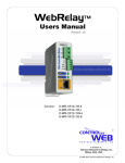
The image below shows the sensor that is shipped with the Temperature Module. It includes the
sensor with 12 inch lead wires. The lead wires are protected at the sensor using over-molding.
Xytronix Research & Design, Inc.
page 10
Revision 1.5
DAQ Series™ Temperature Module Users Manual
1.5 Example Configurations and Applications
The Temperature Module is very versatile and can be used in many applications. Several basic
installation schemes are illustrated in this section.
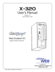
1.5.1 Monitoring Temperature
Monitoring a the temperature read from a digital temperature sensor requires a sensor to be
attached to the Temperature Module, a device capable of requesting and displaying web pages
(Computers, PDA's, etc.), and a network through which the Temperature Module and monitoring
device can communicate. Below is an illustration demonstrating how to connect a temperature
sensor and monitor it on a personal computer. Up to four temperature sensors can be connected
and monitored through the Temperature Module at one time. Also, the temperature readings can
be requested in a XML format which can then be saved to a database, spreadsheet, file, etc.
Software can be created to perform these readings periodically for record keeping.
Xytronix Research & Design, Inc.
page 11
Revision 1.5
DAQ Series™ Temperature Module Users Manual
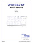
1.5.2 Monitoring Application with Local Alarm
The illustration below shows a simple example of using the Temperature Module to monitor
temperature. The method for wiring the sensor to the Temperature Module is shown. The relays
have been wired to an alarm so that temperatures outside the desired range will sound the alarm.
When the temperature falls below the lower set point or rises above the upper set point, the alarm
will sound. Relay one has been configured to close when a high alarm occurs, and relay two has
been configured to close when a low alarm occurs. See section 2.5.5 for more information on how
to configure the relays, as well as section 3.4.2 to understand how alarm conditions work.
Xytronix Research & Design, Inc.
page 12
Revision 1.5
DAQ Series™ Temperature Module Users Manual
1.5.3 Monitoring Application with Remote Alarm
The following illustration shows an example of using the Temperature Module to monitor
temperature. In this example the Temperature Module has been configured to send messages to
another ControlByWeb™ device with a relay. This relay has then been wired to sound an alarm.
When the temperature falls below the lower set point or rises above the upper set point, a
message will be sent to the remote unit to close it's relay contacts causing the remote alarm to
sound. See section 2.5.5 for more information on how to configure the remote messages, as well
as section 3.4.2 to understand how alarm conditions work.
Xytronix Research & Design, Inc.
page 13
Revision 1.5
DAQ Series™ Temperature Module Users Manual
Section 2: Installation and Setup
Installation consists of mounting the Temperature Module, placing and connecting Digital
Temperature Sensors, connecting to an IP network, providing power, configuring via a web
browser, and wiring relay contacts to the device that will be controlled.
2.1 Mounting
The Temperature Module can be be wall mounted or DIN rail mounted. It should be mounted in a
clean dry location where it is protected from the elements. Ventilation is recommended for
installations where ambient air temperature is expected to be high.
2.1.1 Wall Mounting
Mount the Temperature Module to a wall by using two #8 screws. Attach the screws to the wall
vertically spaced exactly 2.5 inches apart. The head of the screws should be about 1/10 inch
away from the wall. See Appendix C for mechanical details.
2.1.2 DIN-Rail Mounting
The Temperature Module can be mounted to a standard (35mm by 7.55mm) DIN rail. Attach the
Temperature Module to the DIN rail by hooking the top hook on the back of the enclosure to the
DIN rail and then snap the bottom hook into place. Remove Temperature Module from the DIN rail
using a flat-head screwdriver. Insert the screwdriver into the notch in the release tab and pry
against the enclosure to release the bottom hook.
Xytronix Research & Design, Inc.
page 14
Revision 1.5
DAQ Series™ Temperature Module Users Manual
2.2 Digital Temperature Sensor Placement
2.2.1 Temperature Sensor Network Design and Limitations
The connection and placement of the digital temperature sensors in relation to each other and to
the Temperature Module form a network called a '1-wire' network. Multiple sensors can be
connected in two ways, directly connected to the unit (star topology) or “daisy chained” (linear
topology) as shown below. Many factors will determine the maximum length of cable used to
connect sensors to Temperature Module. Some of these factors include, but are not limited to, the
type of cable used, the number of sensors, ambient electromagnetic noise, and sensor network
topology. Combined cable lengths to all sensors of 600 ft using Cat 5e cable have been
successful. However, due to the uniqueness of installation environments, results may vary. Please
test in the desired environment before permanent installation.
The following are general recommendations that will maximize sensor runs and minimize
problems.
Cat 5 and Cat 5e network cable has proven to be an effective and low-cost solution for long runs.
Other cable types can be used, but cable capacitance may limit the length. Figure 2.2j shows the
recommended connection using Cat 5 network cable.
Xytronix Research & Design, Inc.
page 15
Revision 1.5
DAQ Series™ Temperature Module Users Manual
A linear (daisy chain) topology will minimize signal reflections, providing a more reliable connection
and longer cable length that a star topology.
Appropriate strain relief should be used at the Temperature Module and other connections that
may be subjected to vibration, movement, or repeated handling.
Avoid sensor runs adjacent to industrial equipment power cables. These cables can have high
current spikes that may induce noise on the sensor signals. Similarly, avoid running sensor cables
near any radio transmission antennas or coaxial feed-lines.
Protect any electrical connections with appropriate weather shielding.
Due to the broad range of applications and environments were the Temperature Module may be
employed, installation success on long sensor runs may vary significantly.
When daisy chaining sensors, make sure each sensor is attached to the main cable as close as
possible. Having long stubs connecting the sensors to the main cable will cause reflections that
can make the network less reliable. In addition, if longer distances are required, using a heavier
gauge wire will help.
Another approach is to place the Temperature Module close to the sensor(s) and use a longer
Ethernet cable to connect the module to the router or switch.
2.2.2 Digital Temperature Sensor Placement in Monitoring Applications
The placement of the digital temperature sensors depend on the application. The Temperature
Module can act both as a temperature monitor, and a temperature controller. In both cases, cable
length limitations must be considered as described in section 2.2.1 but additional considerations
are described in this section and the next section.
To accurately measure outdoor air temperature, it is recommended that the sensor be placed 5
feet above ground in an open area where it will not be exposed to direct sunlight. If the sensor is
exposed to direct sunlight, or is too close to the ground or other objects that are exposed to direct
sunlight, the temperature reading measured by the sensor will be the current temperature of the
sensor itself instead of the temperature of the air, as the suns rays will heat up the sensor.
If, you need to measure the temperature of a specific object, then the temperature sensor should
be mounted as close to the object as possible, possibly even touching the object.
Regardless of the location of the sensor, if the sensor is placed outside, make sure it is protected
from the elements and that it is secure so wind doesn't blow it around. Also, it is suggested that
the wires be run through a PVC conduit if they are to be placed on the ground to protect them from
the elements.
2.2.3 Digital Temperature Sensor Placement in Control Applications
The Temperature Module can be configure to control a heater or cooling unit. As with monitoring
applications it is important to place the sensor in a location where it will accurately measure the air
temperature and not the temperature of the sensor itself or the temperature of some other object.
Note that in control applications, the reading of the senor will determine how often the heater or
cooler turns on as well as the duration. If the sensor is located too far from the heater or cooler,
the heater or cooler will stay on too long leading to over heating or over cooling. If the sensor too
close to the heater or cooler, then the area surrounding the heater or air conditioner will maintain
the desired temperature, but the rest of the area of interest will be too hot or cold. As a general
rule, sensor placement midway between the heating or cooling unit and the location farthest away
from the heating or cooling unit.
Xytronix Research & Design, Inc.
page 16
Revision 1.5
DAQ Series™ Temperature Module Users Manual
2.3 Connection
CAUTION: MAKE SURE POWER IS SHUT OFF BEFORE WIRING!
A removable 14-terminal connector is provided for simple wiring to the Temperature Module. The
correct wiring procedure is as follows:
1. Make sure power is turned off.
2. Remove terminal connectors from the Temperature Module and make wiring connections
to the terminals.
3. Reconnect terminal connectors.
4. Apply power.
It is recommended that the loads (devices to be controlled) not be connected to the Temperature
Module until after the module has been configured and tested. By doing this, wiring and
configuration mistakes will not cause the load devices to turn on unexpectedly.
IMPORTANT: MAKE SURE WIRES ARE PROPERLY ATTACHED TO THE TERMINALS AND
THAT THE TERMINALS ARE TIGHT!
B a d C o n n e c to r E x a m p le .
S t r a n d ( s ) o f w ir e a r e lo o s e
W ir e s a r e s t r ip p e d t o o f a r b a c k
G o o d C o n n e c t o r E x a m p le .
W ir e s a r e s t r ip p e d c o r r e c t
a m o u n t a n d th e r e a r e n o lo o s e
s tra n d s th a t c a n c a u s e s h o rts
Xytronix Research & Design, Inc.
page 17
Revision 1.5
DAQ Series™ Temperature Module Users Manual
14-Pin Connector Pinout
Pin
Description
VIn+
Power supply input +. Connect to the positive side of the
appropriate power supply. DO NOT EXCEED MAXIMUM
POWER SUPPLY VOLTAGE.
Model X-DAQ-2R1-4T-5
5VDC Power Supply
Model X-DAQ-2R1-4T-I
9-28VDC Power supply
Model X-DAQ-2R1-4T-E
Power Over Ethernet model. These units do not require a
power supply to be connected to this pin when the unit is
connected to an 802.3af compliant network. Alternatively,
this model can be powered using a 5VDC power supply.
Vin+5
Vin- Negative power supply input.
+5VDC Out. This output voltage is used to provide power
for the digital temperature sensors.
Gnd
Ground connection for 5VDC output. Connect to the digital
temperature sensors.
Tmp
Temperature Data. This is the data line connection for the
digital temperature sensors.
1C
Relay 1 Common
1NC
Relay 1 Normally Closed
1NO
Relay 1 Normally Open
2C
Relay 2 Common
2NC
Relay 2 Normally Closed
2NO
Relay 2 Normally Open
2.3.1 Power Supply Connection
The Temperature Module requires power for its internal logic circuits. Connect appropriate power
supply to the Vin+ and Vin- terminals. Alternatively, temperature units with the Power Over
Ethernet option may be powered through the Ethernet connection instead of using an external
power supply.
Multiple temperature modules (and other ControlByWeb™ products) may be connected to a
single power supply by connecting the power supply input terminals in parallel. The power supply
must have a high enough current rating to power all units connected (see specifications for current
requirements for a specific model number).
Temperature Module units with the Power Over Ethernet option may be connected to an 802.3af
compliant Ethernet port instead of connecting to an external power supply. In this case, the
Temperature Module is powered through the network port. In 802.3af compliant networks, a 48
Volt power source is injected into the Ethernet line. This power source is provided by an 802.3af
compliant hub, switch, or power injector which may be located in a utility closet which could be a
distance away from Temperature Module. This option is very useful for installations where local
power is not available. The power injector may inject the 48 Volt power source through the data
lines or the spare lines in the Ethernet cable. DO NOT USE A POWER INJECTOR THAT
APPLIES A VOLTAGE TO BOTH THE DATA LINES AND THE SPARE LINES.
Xytronix Research & Design, Inc.
page 18
Revision 1.5
DAQ Series™ Temperature Module Users Manual
2.3.2 Network Connection
Connect the Ethernet port to a 10 Base T or 10/100 Base T Ethernet connection. This typically
connects to an Ethernet hub, switch, or router. For configuration, the Temperature Module may be
connected directly to the Ethernet port on a computer using a “crossover” cable. Otherwise, for
connection through a hub, switch, or router, a standard “straight-thru” cable should be used.
2.3.3 Relay Connection
The Temperature Module has two internal relays that may be used to control external devices such
as alarms, signals, motors, heaters, etc. The relays can be configured to control devices based
upon temperature measurements or they can simply be turned on and off over the network. The
relay contacts internally connect directly to the terminal connector. If the power source connected
to the relay contacts can deliver more than rated maximum contact current, an external fuse or
circuit breaker must be used. Direct access to Common, Normally Open, and Normally Closed
contacts are provided. The relay contacts may be wired in series with the power source for a
device that will be controlled (the load).
For loads greater than the maximum relay contact rating, an external relay may be used. The
illustration below shows how a 20-Amp motor can be controlled using an external relay. In the
example, the Temperature Module controls the external relay and the external relay controls the
load.
Xytronix Research & Design, Inc.
page 19
Revision 1.5
DAQ Series™ Temperature Module Users Manual
2.3.4 Digital Temperature Sensor Connection
Up to four digital temperature sensors can be connected to the Temperature Module in parallel
using the +5, Gnd, and Tmp terminals (all sensors are connected to the same three terminals).
Sensors purchased from ControlByWeb™ have a red wire for connection to the +5 terminal, a
black wire to connect to the Gnd terminal, and another wire for connection to the Tmp terminal
(may be white, green, or blue). The Tmp terminal is used to connect to the data line of the
temperature sensor. Sensors purchased from other vendors may use different colors so consult
the documentation for the sensor before connecting.
As digital temperature sensors are connected and removed, the Temperature Module maintains a
record of the unique ID numbers of the sensors. This ID number is then used by the Temperature
Module to communicate with the temperature sensors as well as to specify which temperature
sensor is associated with which user options.
Xytronix Research & Design, Inc.
page 20
Revision 1.5
DAQ Series™ Temperature Module Users Manual
2.4 Establishing Communications for Setup
The Temperature Module is set up using a web browser. The first task is to establish
communications between a computer and the Temperature Module so that the browser-based
configuration can begin. To do this, the computer and the Temperature Module must be physically
connected to the same network and both must have IP addresses on the same network. There are
two ways to set up the computer and the Temperature Module so that they are on the same
network. The first way (Option 1), is to change the IP address of the Temperature Module to an
address that is on the same network as the computer. The second way (Option 2) is to change the
IP address of the computer to an address that is on the same network that the Temperature
Module is set to by default.
2.4.1 Option 1: Assign a temporary IP address to the Temperature Module
This option is used to TEMPORARILY assign an IP address to the Temperature Module without
the need to change the IP address of the configuration computer. Note that the Temperature
Module will only use this IP address as long as power is maintained. Once power is lost and
restored, the Temperature Module will use the IP address assigned in the setup page and not the
temporary address assigned here. This means that once communications are established, the
desired IP address should be entered into the network setup page using the browser.
To assign the temporary IP address...
1.
Make sure the Temperature Module and the configuration computer are connected to the same
physical network. This will not work through routers or gateways.
2.
Assign the address as follows...
Windows:
Open a Command Prompt (on Windows XP, select START, then RUN, then type “cmd”).
Type...
arp -s {new IP address} {serial number of temperature module }
Note: IP address format is: xxx.xxx.xxx.xxx
Serial number format is: ss-ss-ss-ss-ss-ss
For example, to set a Temperature Module (with serial number 00-0C-C8-01-00-01 ) to
10.10.10.40 the following command would be used.
arp -s 10.10.10.40 00-0c-c8-01-00-01
Next, type...
ping -l 102 {new IP address}
For example, if the new IP address is 10.10.10.40, the following command would be
used.
ping -l 102 10.10.10.40
Linux/Unix:
Open a terminal, change to root user (su -, then enter root password).
Type...
arp -s {new IP address} {serial number of temperature module}
Note: IP address format is: xxx.xxx.xxx.xxx
Serial number format is: ss:ss:ss:ss:ss:ss
For example, to set a Temperature Module (with serial number 00-0C-C8-01-00-01 ) to
Xytronix Research & Design, Inc.
page 21
Revision 1.5
DAQ Series™ Temperature Module Users Manual
10.10.10.40 the following command would be used.
arp -s 10.10.10.40 00:0c:c8:01:00:01
Next, type...
ping -s 102 {new IP address}
For example, if the new IP address is 10.10.10.40, the following command would be
used.
ping -s 102 10.10.10.40
Mac OS X
Open a terminal,
Note that the terminal is in the “Utilities” directory which is in “Applications” directory.
type
sudo arp -s {new IP address} {serial number of temperature module}
Note: Administrator password is required.
IP address format is: xxx.xxx.xxx.xxx
Serial number format is: ss:ss:ss:ss:ss:ss
For example, to set a Temperature Module (with serial number 00-0C-C8-01-00-01 ) to
10.10.10.40 the following command would be used.
sudo arp -s 10.10.10.40 00:0c:c8:01:00:01
Next, type...
ping -s 102 {new IP address}
For example, if the new IP address is 10.10.10.40, the following command would be
used.
ping -s 102 10.10.10.40
Xytronix Research & Design, Inc.
page 22
Revision 1.5
DAQ Series™ Temperature Module Users Manual
2.4.2 Option 2: Assign a temporary IP address to configuration computer
If the first option above is not used, you can use this option to communicate with the Temperature
Module. By default, Temperature Module comes from the factory with an IP address of
192.168.1.2. Communications with Temperature Module may be established by assigning an IP
address to the configuration computer that is on the same network as Temperature Module(for
example, the configuration computer could be assigned to 192.168.1.5) .
Instructions for changing the IP address of the computer that will be used for the Temperature
Module configuration are given here. Note that these instructions are specifically for computers
with the Windows XP operating system. For setup using other operating systems, refer to the
appropriate users manual.
Step 1
Open the control panel by clicking on the start menu and then clicking on Control Panel. (Note
that control panel shown is in “Classic View”. If control panel is in “Category View” select the
“Classic View” option before proceeding.)
Xytronix Research & Design, Inc.
page 23
Revision 1.5
DAQ Series™ Temperature Module Users Manual
Step 2:
Double click on the icon labeled Network Connections. The following menu will pop up.
Step 3:
Right click on the icon labeled Local Area Connection. Another menu will appear. Select the option
at the bottom of the menu labeled Properties. The Local Area Connection Properties window will
appear.
Xytronix Research & Design, Inc.
page 24
Revision 1.5
DAQ Series™ Temperature Module Users Manual
Step 4:
On the Local Area Connection Properties page scroll down to Internet Protocol (TCP/IP), select it,
and then click the button labeled properties.
Step 5:
Before making any changes to the network settings, write down the current settings so that they
can be restored once the Temperature Module is configured. Next, select the radio button labeled
“Use the following IP address,” and type in the IP address 192.168.1.50. Type in a subnet mask of
255.255.255.0. Leave the default gateway field blank. Click OK to apply the new settings.
2.4.3 Open Configuration Web Page
Once the network is set up, open the configuration setup page by typing the following URL into the
browser: http://192.168.1.2/setup.html (note that if option 1 above was used for initial
configuration, replace the IP address given here with the newly assigned IP address). A password
is required to change any parameters. The default password is ‘webrelay’ (do not include quotes,
password is case sensitive).
Xytronix Research & Design, Inc.
page 25
Revision 1.5
DAQ Series™ Temperature Module Users Manual
2.5 Web-Based Setup
The Temperature Module is fully configurable through HTML 4.0 compliant web browsers such as
Internet Explorer and Mozilla Firefox. It’s easy to use tab based menu system has been designed
to allow the unit to be configured easily. Note that in this chapter, the default IP address of
192.168.1.2 is used in all examples. If the IP address has been changed, substitute the new IP
address for the address shown in the examples.
Before proceeding, make sure a network connection has been established between the computer
and the Temperature Module. This is done by typing the following URL into the web browser:
http://192.168.1.2/setup.html. Another way to check communications is to ping the Temperature
Module (from the command prompt (type ping 192.168.1.2)). Each setup page is described below.
2.5.1 Setup Page
This is the initial page that appears when the URL http://192.168.1.2/setup.html is entered into the
web browser. It provides basic information about the unit. Navigating between setup pages is
done by clicking on the tabs at the top of the page.
All setup pages require a password. The default password is ‘webrelay’ (no quotes, all lower case)
and no user name is required.
Xytronix Research & Design, Inc.
page 26
Revision 1.5
DAQ Series™ Temperature Module Users Manual
Each setup page has a “Submit” button and a “Reset” button at the bottom of the page. After
entering the desired parameters into each page, the “Submit” button must be pressed before any
parameters will be saved. If a mistake is made in entering the parameters, the “Reset” button may
be used to restore all parameters on the page to their current settings. The “Reset” button is only
effective before the “Submit” button is pressed.
Xytronix Research & Design, Inc.
page 27
Revision 1.5
DAQ Series™ Temperature Module Users Manual
2.5.2 Network Setup Page
The network parameters are changed on this page. Note that if multiple temperature modules are
used on the same network, install one unit at a time and set the IP address of each unit before
connecting the next unit to the network. This avoids having multiple units installed on the network
with the same factory default IP address at the same time. It may be necessary to clear the arp
cache each time you swap temperature modules on the network (this is because each unit has the
same default IP address but a different mac address). This is done by typing arp -d in the
command prompt of a Windows computer (arp -d -a as super user on Apple OSX). Also note that
the unit must be power-cycled (power disconnected, then reconnected) before network settings
take effect. No other setup page requires power-cycling for the settings to take effect.
IP Address
The Temperature Module requires a static IP address. This is a unique address that identifies
the Temperature Module on the network. Dynamic IP address assignment is not supported.
The lack of dynamic IP addressing support is intentional because dynamically changing the IP
address would make it difficult for a client to access the web server built into the Temperature
Module. The IP address is specific to the network where the unit will be installed, and must be
obtained from the network administrator.
This guide is not meant to be a tutorial on IP addressing, however a few comments about IP
addressing are given here.
If the Temperature Module will be used over the Internet, the IP address must be a routable
address assigned by the upstream Internet Service Provider (ISP).
In cases where the ISP only provides a single routable IP address for the entire network (this
is typical with ISPs such as cable providers), a proxy server (or gateway router) may be used.
A proxy server allows multiple devices to connect to the Internet using a single routable IP
address. Many small routers from LinkSys, Dlink, and Netgear perform proxy server functions.
Xytronix Research & Design, Inc.
page 28
Revision 1.5
DAQ Series™ Temperature Module Users Manual
If a proxy server is used, the Temperature Module will not be accessible from the Internet until
the proxy server is properly configured (forward proper port to the Temperature Module). This
information is mentioned for convenience but details of setting up a configuration such as this
is beyond the scope of this manual.
If the Temperature Module is used on a private network only and is NOT used over the
Internet, a routable IP address is not necessary. This may be the case when the Temperature
Module is used to control a device in another room or a nearby building.
If the Temperature Module will be installed on a simple, private network that does not connect
to the Internet, the default IP address may be used as long as no other device on the network
uses the same address. If multiple units are installed on the same network, each unit must
have its own unique IP address. For example, the Temperature Module comes from the
factory with a default IP address of 192.168.1.2. If multiple units are used, change the IP
address for each unit (192.168.1.3, 192.168.1.4, 192.168.1.5 etc.).
Netmask
This specifies the size of the local network. This must be obtained from the network
administrator. By default, the netmask is set to 255.255.255.0.
Broadcast
This specifies the broadcast address. This must be obtained from the network administrator.
By default, this is set to 192.168.1.255.
Gateway
This specifies the IP address of the gateway router. This must be obtained from the network
administrator. By default, this is set to 192.168.1.1.
TCP Port
This specifies the TCP port used for communications with the Temperature Module. By
default, the port is set to 80 which is the standard http port. It is recommended that the port
not be changed without an understanding of TCP/IP and ports.
Changing the port can be useful for accessing multiple temperature modules which are
installed behind a gateway router on a private network that uses non-routable IP addresses
(192.168.x.x, 10.x.x.x, and 172.16.x.x through 172.31.x.x are non-routable or private IP
addresses). In this case, each Temperature Module would be assigned a different port (for
example 8000, 8001, 8002, etc). The gateway router would be set up to forward all traffic for
each of the assigned ports to the IP address of the Temperature Module which uses that port.
The temperature modules could then be accessed from outside the private network by
entering the IP address of the gateway and the port for the desired Temperature Module. Note
that whenever any port is assigned other than port 80, all communications with that
Temperature Module must include the port. For example, if the Temperature Module is
assigned port 8000, access to the setup page would require the following URL to be entered;
http://192.168.1.2:8000/setup.html.
An example screenshot of a gateway router configuration is given below. This setup allows
seven ControlByWeb™ products to be accessed on a private network behind a gateway
router. Note that this screenshot is simply an example of a typical router setup page. Routers
will vary.
Xytronix Research & Design, Inc.
page 29
Revision 1.5
DAQ Series™ Temperature Module Users Manual
In the example, the seven ControlByWeb™ products are assigned IP addresses of
10.10.10.41 to 10.10.10.47. The first device labeled WebRelay 1 has an IP address of
10.10.10.41 and is assigned port 8001. Note that in the WebRelay™setup page (under
Network settings tab), TCP Port 8001 must be specified for this device. The second device,
labeled WebRelay 2 has an IP address of 10.10.10.42 and is assigned port 8002. This
WebRelay™ must have its TCP Port set to 8002 in it's network settings page. This pattern
continues through 10.10.10.77 which is assigned the port 8007. To access the
ControlByWeb™ units from the Internet, enter the IP address of the gateway plus the port
number of the desired device.
Modbus Port
This specifies the port used for Modbus/TCP communications with the Temperature Module.
By default this is set to port 502 which is the standard Modbus port. For users not familiar with
Modbus, Modbus is a messaging structure protocol used in industrial manufacturing control
and automation. It is an open protocol and offers interoperability with software and devices
from other manufacturers. If Modbus is not used, this setting can be ignored. Modbus
communications are disabled whenever the control password is enabled.
Speed
This option sets the data rate of the Ethernet port. Both 10Mbps and 100Mbps can be
selected. The 100Mbps option offers faster communications but the amount of data to and
from the Temperature Module is so small that users will not likely notice much of a difference.
When the Temperature Module is set to 10Mbps, it draws less power and runs a little cooler
which translate into a longer product life. IT IS RECOMMENDED THAT THIS SETTING BE
LEFT AT 10MBPS UNLESS THE USER HAS A SPECIFIC REASON TO USE 100MBPS.
Mode
This option allows the Ethernet port to be set to Half Duplex or Full Duplex. Legacy Ethernet
operates in Half Duplex mode which means that devices can either send data or receive data,
but not both at the same time. Full duplex means that devices can send and receive data at
the same time.
Xytronix Research & Design, Inc.
page 30
Revision 1.5
DAQ Series™ Temperature Module Users Manual
MTU Setting
To change the MTU, manually enter the advSetup.html (case sensitive) page into the address
bar. (http://192.168.1.2/advSetup.html). This new setup page will have a text box that will allow
the MTU to be changed. The valid range is 256 to 1476 bytes. MTU is a network parameter
that stands for Maximum Transmission Unit. This defines the max size, in bytes, of the TCP
packets sent out from the device. This normally can be left alone, but there are some
circumstances where it might be beneficial to change it. One of these circumstances is when
the device is to be used over a VPN (virtual private network). VPN's add extra information to
TCP packets, if the new packets are too big to physically travel across the network (greater
than about 1500 bytes) then the packets will be split up. This causes problems for some
firewalls and those firewalls will just discard the packets. To fix this, the MTU can be adjusted
until the TCP packets do not get split up.
Xytronix Research & Design, Inc.
page 31
Revision 1.5
DAQ Series™ Temperature Module Users Manual
2.5.3 Email Setup Page
The settings on this page are used when the device has been configured to send email messages.
The Temperature Module requires a SMTP server to send email messages and can be configured
to use basic authentication.
DNS Address
If Email notification will be used, enter the IP address of a DNS server. This is used to lookup
the IP address of the mail server. If the IP address of the SMTP server is known, the DNS
server can be bypassed by leaving the Mail Server field blank and entering the IP address of
the SMTP server directly into the DNS Address field.
Mail Server (SMTP)
If email notification will be used, enter the SMTP email server in this field. This is the name of
the server (for example... mail.example.com). To use this SMTP server, the Temperature
module must first determine the IP address of the SMTP server. This is usually done by using
a DNS server. If the IP address of the SMTP server is known, the use of aDNS server can be
eliminated. This is done by leaving this field blank and entering the IP address of the SMTP
server directly into the DNS Address field. This will skip the domain name lookup.
Mail Server Port
If email notification will be used, enter the port number used by the SMTP server. Port 25 is
the standard port for SMTP.
Xytronix Research & Design, Inc.
page 32
Revision 1.5
DAQ Series™ Temperature Module Users Manual
Domain
If email notification will be used, enter a domain name that will be used when communicating
with the SMTP server.
User Name
Most ISPs require authentication to access their mail servers from outside the network, but do
not require authentication from inside the network. If authentication is required, enter the username here. If authentication is not used, leave this field blank.
Password
Most ISPs require authentication to access their mail servers from outside the network, but do
not require authentication from inside the network. If authentication is required, enter the
password here. If authentication is not used, leave this field blank.
Return Email
If email notification will be used, enter the return email address (sender email address) here.
Email 1 Address
If email notification will be used, enter the email address of the first recipient of notification
messages.
Email 2 Address
If email notification will be used and messages will be sent to at least two recipients, enter the
email address of the second recipient of email notification messages.
Email 3 Address:
If email notification will be used and messages will be sent to three recipients, enter the email
address of the third recipient of email notification messages
Xytronix Research & Design, Inc.
page 33
Revision 1.5
DAQ Series™ Temperature Module Users Manual
2.5.4 Password Setup Page
The password setup page is used to change and enable passwords. A password is required
for the setup pages but is optional for the control page. The password is enabled or disabled
for the control page by using the Yes or No radio buttons. Enabling the control page password
also enables the requirement for a password when reading/writing XML pages. Enabling the
control page password also disables the ability to communicate with the Temperature Module
using Modbus. Note that when the password is changed, the password may be displayed in
the browser’s history in clear text. It is advisable to clear the browsers history after setting the
password. Passwords may be alpha-numeric passwords up to 10 characters.
Xytronix Research & Design, Inc.
page 34
Revision 1.5
DAQ Series™ Temperature Module Users Manual
2.5.5 Main Setup Page
The main setup page is used mainly to set parameters that effect the view of the control page, how
often it will refresh, etc. It is here that the units of measurement may also be specified.
Units
This option specifies the units which will be used for temperature readings. The available
options are degrees Fahrenheit and Celsius.
Main Header Text
The text entered here appears at the top of the control page. It also appears in the header of
the email text when the email notification is used. This field can be up to 25 characters in
length.
Xytronix Research & Design, Inc.
page 35
Revision 1.5
DAQ Series™ Temperature Module Users Manual
Auto Refresh Page
Web pages traditionally display static information. The Temperature Module control page,
however, displays information that is dynamic. Each time the control page is loaded to the
browser, it displays a snapshot of the current status of the unit. Whenever the state of a
sensor changes, the control page will be obsolete until the page is refreshed. The
Temperature Module cannot force the web page to be updated when the sensors update.
The 'Auto Refresh Page' option will cause the control page to continually update its contents
by setting a timer in the web page that causes it to be reloaded at a specified time interval.
Duration
When the 'Auto Refresh Page' option is set to YES, this field specifies the time interval in
seconds that the page will be refreshed. It can be set from 1 to 32 seconds.
Display Sensor 1 Temp
When this option is set to Yes, the most recent reading of the digital temperature sensor
associated with sensor 1 will be displayed in the control page. This setting also enables or
disables the sensor 1 status in email alert messages (must be set to Yes for the most recent
temperature reading associated with sensor 1 to appear in email alert messages.)
Display Sensor 1 Set Temp
When this option is set to Yes, a editable text field, along with a button labeled 'Apply', will
appear on the control page. The set temperature for sensor 1 can be changed by editing the
temperature in the text field and pressing the 'Apply' button. The set temp applies either to the
high alarm or low alarm for sensor 1. Whether or not it applies to the high or low alarm is
determined by the next option.
Set Temp Displayed
This option determines whether or not the set temperature is applied to the High Alarm or
Low Alarm when it is changed through the control page.
Display Sensor 2 Temp
When this options is set to Yes, the most recent reading of the digital temperature sensor
associated with sensor 2 will be displayed in the control page. This setting also enables or
disables the sensor 2 status in email alert messages (must be set to Yes for the most recent
temperature reading associated with sensor 2 to appear in email alert messages.)
Display Sensor 3 Temp
When this options is set to Yes, the most recent reading of the digital temperature sensor
associated with sensor 3 will be displayed in the control page. This setting also enables or
disables the sensor 3 status in email alert messages (must be set to Yes for the most recent
temperature reading associated with sensor 3 to appear in email alert messages.)
Display Sensor 4 Temp
When this options is set to Yes, the most recent reading of the digital temperature sensor
associated with sensor 4 will be displayed in the control page. This setting also enables or
disables the sensor 4 status in email alert messages (must be set to Yes for the most recent
temperature reading associated with sensor 4 to appear in email alert messages.)
Display Relay 1 State
When this options is set to Yes, the relay status for relay 1 will be displayed on the control
page. If it is set to No, the relay status for relay 1 will not be displayed.
Xytronix Research & Design, Inc.
page 36
Revision 1.5
DAQ Series™ Temperature Module Users Manual
Display Relay 1 ON/OFF Buttons
When this option is set to Yes, the ON/OFF buttons for relay 1 will be displayed in the control
page. If it is set to No, the ON/OFF buttons for relay 1 will not be displayed.
Display Relay 1 Pulse Button
When this option is set to Yes, the Pulse button for relay 1 will be displayed in the control
page. If it is set to No, the Pulse button for relay 1 will not be displayed.
Display Relay 2 State:
When this options is set to Yes, the relay status for relay 2 will be displayed on the control
page. If it is set to No, the relay status for relay 2 will not be displayed.
Display Relay 2 ON/OFF Buttons:
When this option is set to Yes, the ON/OFF buttons for relay 2 will be displayed in the control
page. If it is set to No, the ON/OFF buttons for relay 2 will not be displayed.
Display Relay 2 Pulse Button:
When this option is set to Yes, the Pulse button for relay 2 will be displayed in the control
page. If it is set to No, the Pulse button for relay 2 will not be displayed.
Xytronix Research & Design, Inc.
page 37
Revision 1.5
DAQ Series™ Temperature Module Users Manual
2.5.6 Sensor Setup Pages
These pages (Sensor 1 through Sensor 4) define which digital temperature sensor is associated
with which sensor number, and define how alarms and email alert messages are handled. All four
pages are identical with the exception of the Sensor 1 page which also includes additional settings
for controlling both the local relays as well as remote ControlByWeb™ devices based on alarm
conditions.
Xytronix Research & Design, Inc.
page 38
Revision 1.5
DAQ Series™ Temperature Module Users Manual
The first 6 parameters appear on all the Sensor pages. The remaining parameters appear on the
Sensor 1 page only.
Sensor Description
The text in this field appears to the left of the temperature reading associated with the sensor.
This text also appears in the email status messages when that feature is enabled. This field
can be up to 20 characters in length.
Sensor Address
Every digital temperature sensor has a unique id number associated with it. In order to
associate a digital temperature sensor with a sensor number, this field should be set to
correspond with the id number of the desired digital temperature sensor. The drop down box
will list the id numbers of all the digital temperature sensor currently connected to the
Temperature Module (these are automatically detected.) When first connecting the digital
temperature sensor, it is useful to connect one at a time and then press the refresh button in
the browser to update the list of id numbers in the drop down box. This way it can be
determined which id number belongs to which digital temperature sensor. If for some reason
the id number associated with one of the digital temperature sensors doesn't appear in the
drop down box, you may select the option Other... at which point the the drop down box will
change into a text box where the id number can be directly entered. If the id number entered
isn't valid, temperature readings will cannot be read.
High Alarm/Set
This option determines the trigger point for high alarms. This value should be greater than
the low alarm set point. When the temperature read from the digital temperature sensor is
greater than this value, a high alarm condition exists. The actions taken as a result are
determined by the other parameters on this setup page. Sensors 2 through 4 can only send
alert emails as a result of a high alarm. Sensor 1 can send out alert emails as well as change
the state of the local relays and up to two remote relays on other ControlByWeb™ devices.
Low Alarm/Set
This option determines where the trigger point is for low alarms. This value should be less
than the high alarm set point. When the temperature read from the digital temperature sensor
is lower than this value, a low alarm condition exists. The actions taken as a result are
determined by the other parameters on this setup page. Sensors 2 through 4 can only send
alert emails as a result of a low alarm. Sensor 1 can send out alert emails as well as change
the state of the local relays and up to two remote relays found on other ControlByWeb™
devices.
Deadband
This option specifies the deadband used when evaluating alarm conditions. Deadband
prevents alarms or relays from toggling excessively when measured temperature is at the set
point. This is due to normal fluctuating. For example, if the deadband is set to 1 degree, and a
high alarm is to occur at 95 degrees, the dead band ensures that once the high alarm is
triggered, it won't go off until the temperature return below 94 degrees (95 – 1). This reduces
problems with small fluctuations in temperature readings triggering multiple alarms. The
deadband is also used during low alarm conditions. If for example a low alarm is to occur at
45 degrees and the dead band is set to 1 degree, then once the low alarm is triggered, it won't
go off until the temperature returns higher than 46 degrees (45 + 1).
Xytronix Research & Design, Inc.
page 39
Revision 1.5
DAQ Series™ Temperature Module Users Manual
Email Options
Simple email messages can be sent in response to alarm conditions. This parameter is used
to specify what alarm conditions, if any, will cause email messages to be sent. Note that email
notification will work only if the 'DNS Address', Mail Server (SMTP)', and 'Email 1 Address' are
correctly set up in the Network setup page.
- No Email Messages- No email messages will be sent due to alarm conditions.
- Send High Alarm, and Low Alarm Messages- Email messages will be sent out due
to high and low alarm conditions.
- Send High Alarm, Normal, and Low Alarm Messages- Email messages will be sent
out due to high, normal, and low alarm conditions.
Use Email Address
If email messages are to be sent out based on alarm conditions, these check boxes specify to
which email addresses the message will be sent. Each check box corresponds to one email
address specified on the email setup page.
Relay 1 Description
This text is used to describe the function of relay 1 on the control page. This text will not
appear unless the relay 1 status is visible, or the ON/OFF buttons or Pulse button for relay 1
are enabled. This field can be up to 20 characters in length.
Xytronix Research & Design, Inc.
page 40
Revision 1.5
DAQ Series™ Temperature Module Users Manual
Relay 1 Options
This parameter is used to specify if and how relay number 1 will react to high alarm
conditions. Note that relay 1 only reacts to high alarm conditions, meaning it can be setup to
change states when a high alarm condition exists, and then return to its previous state when a
normal alarm occurs. The options in the drop down list are described below. Also note that
once the relay reacts to an alarm condition, users may change the state of the relay from the
web browser even if the alarm condition remains.
-
No Relay Control – Take no action when a high alarm occurs.
Relay On when High Alarm – Turn the relay on when a high alarm occurs.
Relay Off when High Alarm – Turn the relay off when a high alarm occurs.
Relay Pulse when High Alarm – Pulse the relay when a high alarm occurs.
Relay 1 Pulse
This parameter determines the pulse duration used when relay 1 is set to pulse when a high
alarm occurs or when the pulse button is pressed on the control page. This time can be set
from 0.1 seconds to 86,400 seconds (1 day).
Relay 2 Description
This text is used to describe the function of relay 2 on the control page. This text will not
appear unless the relay 2 status is visible, or the ON/OFF buttons or Pulse button for relay 2
are enabled. This field can be up to 20 characters in length.
Relay 2 Option
This parameter is used to specify if and how relay number 2 will react to low alarm conditions.
Note that relay 2 only reacts to low alarm conditions, meaning it can be setup to change states
when a low alarm condition exists, and then return to its previous state when a normal alarm
occurs. The options in the drop down list are described below. Also note that once the relay
reacts to an alarm condition, users may change the state of the relay from the web browser
even if the alarm condition remains.
-
No Relay Control – Take no action when a low alarm occurs.
Relay On when Low Alarm – Turn the relay on when a low alarm occurs.
Relay Off when Low Alarm – Turn the relay off when a low alarm occurs.
Relay Pulse when Low Alarm – Pulse the relay when a low alarm occurs.
Relay 2 Pulse
This parameter determines the pulse duration used when relay 2 is set to pulse when a low
alarm occurs or when the pulse button is pressed on the control page. This time can be set
from 0.1 seconds to 86,400 seconds (1 day).
Xytronix Research & Design, Inc.
page 41
Revision 1.5
DAQ Series™ Temperature Module Users Manual
Remote Relay 1 Option
This parameter is used to specify if and how the remote relay number 1 will react to high alarm
conditions. Note that remote relay 1 only reacts to high alarm conditions, meaning it can be
setup to change states when a high alarm condition exists, and then return to its previous
state when a normal alarm occurs. The options in the drop down list are described below. Also
note that once the remote relay reacts to an alarm condition, user may change the state of
the relay from the web browser even if the alarm condition remains.
-
No Relay Control – Take no action when a high alarm occurs.
Relay On when High Alarm – Turn the remote relay on when a high alarm occurs.
Relay Off when High Alarm – Turn the remote relay off when a high alarm occurs.
Relay Pulse when High Alarm – Pulse the remote relay when a high alarm occurs.
Note that the amount of time the remote relay will pulse is determined by the user settings in
that unit and not by any of the local settings.
Remote Relay 1 IP Address:
When any option in the 'Remote Relay 1 Option' setting is selected other than No Relay
Control, commands are sent over the IP network to this address as alarm conditions change.
Remote Relay 1 TCP Port:
When any option in the 'Remote Relay 1 Option' setting is selected other than No Relay
Control, commands are sent over the IP network to this TCP port on the remote
ControlByWeb™ device as alarm conditions change.
Remote Relay1 Password
If remote messages are to be sent to a remote device that requires a password, the password
entered in this field will be used.
Remote Relay 1 Relay #:
When any option in the 'Remote Relay 1 Options' setting is selected other than No Relay
Control, commands are sent to the remote device with this relay offset. This option should
ALWAYS be set to 0, unless the remote device is something other than WebRelay™ . This is
used, for example, when the remote device has multiple relays. For example, WebRelayQuad™ has 4 relays. To send commands to the third relay on WebRelay-Quad™ , this option
would be set to 3. To send commands to the first relay on WebRelay-Quad™, this option
would be set to 1. This field may be set from 0 to 255.
Remote Relay 1 Periodic State Interval:
When any option in the 'Remote Relay 1 Option' setting is selected other than No Relay
Control, this parameter controls whether or not periodic messages should be sent out as well
as messages that get sent out as alarm conditions change. This setting has the range of 10 to
4223173 seconds (roughly 48 days).
Xytronix Research & Design, Inc.
page 42
Revision 1.5
DAQ Series™ Temperature Module Users Manual
Remote Relay 2 Options:
This parameter is used to specify if and how the remote relay number 2 will react to low alarm
conditions. Note that remote relay 2 only reacts to low alarm conditions, meaning it can be
setup to change states when a low alarm condition exists, and then return to its previous state
when a normal alarm occurs. The options in the drop down list are described below. Also note
that once the remote relay reacts to an alarm condition, users may change the state of the
relay from the web browser even if the alarm condition remains.
-
No Relay Control – Take no action when a low alarm occurs.
Relay On when Low Alarm – Turn the remote relay on when a low alarm occurs.
Relay Off when Low Alarm – Turn the remote relay off when a low alarm occurs.
Relay Pulse when Low Alarm – Pulse the remote relay when a low alarm occurs.
Note that the amount of time the remote relay will pulse is determined by the user settings in
that unit and not by any of the local settings.
Remote Relay 2 IP Address
When any option in the 'Remote Relay 2 Option' setting is selected other than No Relay
Control, commands are sent over the IP network to this address as alarm conditions change.
Remote Relay 2 TCP Port
When any option in the 'Remote Relay 2 Option' setting is selected other than No Relay
Control, commands are sent over the IP network to this TCP port on the remote
ControlByWeb™ device as alarm conditions change.
Remote Relay 2 Password
If remote messages are to be sent to a remote device that requires a password, the password
entered in this field will be used.
Remote Relay 2 Relay #
When any option in the 'Remote Relay 2 Option' setting is selected other than No Relay
Control, commands are sent to the remote device with this relay offset. This option should
ALWAYS be set to 0, unless the remote device is something other than WebRelay™ . This is
used, for example, when the remote device has multiple relays. For example, WebRelayQuad™ has 4 relays. To send commands to the third relay on WebRelay-Quad™ , this option
would be set to 3. To send commands to the first relay on WebRelay-Quad™, this option
would be set to 1. This field may be set from 0 to 255.
Remote Relay 2 Periodic State Interval
When any option in the 'Remote Relay 2 Option' setting is selected other than No Relay
Control, this parameter controls whether or not periodic messages should be sent out as well
as messages that get sent out as alarm conditions occur. This setting has the range of 10 to
4223173 seconds (roughly 48 days).
Xytronix Research & Design, Inc.
page 43
Revision 1.5
DAQ Series™ Temperature Module Users Manual
Section 3: Operation
The Temperature Module can be operated using a web browser, by sending text commands to an
XML status/control page, or by sending Modbus/TCP requests. The Temperature Module can also
be configured to control the local relays as well as remote ControlByWeb™ devices based on
alarm conditions.
3.1 Browser Operation
Once the unit is set up, the control page may be accessed by typing the following URL into the
web browser: http://192.168.1.2 (Note that if the IP address was changed, replace the default IP
address shown with the new address that was assigned. Note also that if any port is used other
than port 80, the port must also be included in the request: http://192.168.1.2:8000 ) The new
control page will appear. A control page with default settings is shown below. Note that any
sensors that have not been assigned to a specific digital temperature sensor will display xx.x in the
control page, XML page, and alert emails. The control page allows the user to turn the individual
relays on and off as well as monitor the current temperature of the digital temperature sensors. It is
here that the set temperature for sensor 1 alarms can be changed. To change the set temperature
for sensor 1 through the control page enter the new set temperature in the text field to the right of
the heading 'Sensor 1 Set Temp.' and then push the 'Apply' button. The set temperature will apply
to either the high alarm set temperature or low alarm set temperature depending on the setting of
the parameter 'Set Temp Applies To' on the main setup page. When the set temperature is
changed, all active alarms will be reevaluated immediately and the local relays as well as remote
devices will be updated based on the user settings. Email alerts will be sent out accordingly as
well.
Xytronix Research & Design, Inc.
page 44
Revision 1.5
DAQ Series™ Temperature Module Users Manual
3.2 XML Operation
Custom computer applications may be created to monitor and control the Temperature Module
without using a web browser. Monitoring the temperatures and the relays is done by sending a
request to port 80 (or port specified in setup) for the XML page. Control of the relay is done by
sending GET requests to the same page on port 80 (or port specified in setup). This can be
demonstrated by entering commands into the URL line of a web browser.
3.2.1 state.xml
Request the current state: http://192.168.1.2/state.xml
This will return the following XML page.:
<?xml version="1.0" encoding="utf-8" ?>
<datavalues>
<units>F</units>
<sensor1temp>xx.x</sensor1temp>
<sensor2temp>xx.x</sensor2temp>
<sensor3temp>xx.x</sensor3temp>
<sensor4temp>xx.x</sensor4temp>
<relay1state>0</relay1state>
<relay2state>0</relay2state>
</datavalues>
The tags <units>, <sensortemp> and <relaystate> indicate the current state of the Temperature
Module. Values for each tag are described below.
Tags*
Description
<units>
F (Degrees Fahrenheit)
C (Degrees Celsius)
<sensorXtemp>
xx.xx (indicates that no digital temperature sensor is
associated with the sensor number)
80.10 (temperature reading from digital temperature
sensor associated with the sensor number)
0 = OFF (coil off)
1 = ON (coil energized)
* 'X' is replaced by the sensor or relay number
<relayXstate>
Note: The XML reply does not contain headers. To generate an XML reply with headers use the
following command:
Command
Description
stateFull.xml
Return the XML reply with headers
Xytronix Research & Design, Inc.
page 45
Revision 1.5
DAQ Series™ Temperature Module Users Manual
3.2.2 XML Control
Commands can be sent to the Temperature Module that control the relays and change their states.
Relay State Control
Commands are sent using a variable called relayState. Two examples of using relayState are
given here.
Note: The IP address of the device would be included on all the following commands.
Example: http://192.168.1.2/state.xml?relay1State=1
Command
Description
state.xml?relay1State=0
Turn Relay 1 OFF
state.xml?relay1State=1
Turn Relay 1 ON
state.xml?relay2State=2
Pulse Relay 2
state.xml?relay2State=5
Toggle Relay 2 State
Pulse Relay
When the pulse command is sent to one of the relays, the relay will pulse for the time specified in
the setup page. It is possible however to specify a pulse time that is different than the pulse time
configured in the setup page. This is done by sending an additional variable called pulseTime and
the desired pulse time.
The pulseTime variable does not change the pulse time specified in the setup page and it is not
stored or recorded. The pulseTime variable only changes the pulse duration for the single pulse
initiated by that command. In other words, you must issue the pulseTime for each pulse command
that differs from the preset pulse time. For example, suppose the pulse time for relay 2 is set to
1.5 seconds in the configuration pages. To issue one 1.5 second pulse, three five second pulses,
and a 1.5 second pulse once again, you would issue the following commands...
Command
Description
state.xml?relay1State=2
Pulse Relay 1 for the preset time
(1.5 seconds).
state.xml?relay1State=2&pulseTime1=5
Pulse Relay 1 for 5 seconds.
state.xml?relay1State=2&pulseTime1=5
Pulse Relay 1 for 5 seconds.
state.xml?relay1State=2&pulseTime1=5
Pulse Relay 1 for 5 seconds.
state.xml?relay1State=2
Pulse Relay 1 for the preset time
(1.5 seconds).
Set Temperature for Sensor 1
The set temperature can be changed through the control page as well as issuing commands
directly from another application. For example, to change the set temperature of sensor 1 through
another application issue the following command.
http://192.168.1.2/index.srv?setTemp=90.2&7=Apply
In response to this command the Temperature Module will return the control page with the updated
set temperature.
Xytronix Research & Design, Inc.
page 46
Revision 1.5
DAQ Series™ Temperature Module Users Manual
Message Acknowledgment
When commands are sent to the Temperature Module, its current state is returned in the form of
an XML page.
Note: The XML reply does not contain headers. To generate an XML reply with headers use the
following command:
Command
Description
stateFull.xml
Return the XML reply with headers
The commands can also be sent without having the Temperature Module return the XML page.
This is accomplished by adding the noReply field as follows.
Command
Description
state.xml?relayState=1&noReply=1
Turn Relay ON without returning state.
state.xml?relayState=0&noReply=1
Turn Relay OFF without returning state.
Xytronix Research & Design, Inc.
page 47
Revision 1.5
DAQ Series™ Temperature Module Users Manual
3.2.3 GET Requests
GET requests can be used by custom applications to monitor and control the relay, and the alarm
temperature. A few example GET requests are provided below
No Password Enabled:
GET requests to the device for specific files
Example: Request home.html
GET /home.html HTTP/1.1\r\n\r\n
Example: Turn Relay 1 ON
GET /state.xml?relay1State=1 HTTP/1.1\r\n\r\n
Password Enabled:
If the control password is enabled in the Temperature Module and the XML page is requested
through a browser, the browser will prompt the user for the password. If the XML request is sent
from another application and not a browser, the html request will need to contain the password
encoded using the base 64 encoding scheme. The html request header without the password
looks like this:
GET /state.xml?noReply=1 HTTP/1.1 (Terminated with two \r\n)
The html request header with the password looks like this:
GET /state.xml?relayState=1&noReply=1 HTTP/1.1 (Terminated with one \r\n)
Authorization: Basic bm9uZTp3ZWJyZWxheQ== (Terminated with two \r\n)
Where bm9uZTp3ZWJyZWxheQ== is the base 64 encoded version of the username and
password none:webrelay
A utility is provided at http://www.ControlByWeb.com/encoder that can be used to encode the
password. The utility is used by simply typing the string username:password into the website and
pressing encode.
Xytronix Research & Design, Inc.
page 48
Revision 1.5
DAQ Series™ Temperature Module Users Manual
3.3 Modbus Operation
The Temperature Module can be controlled (and read) using Modbus/TCP protocol. This provides
a standard means of using the Temperature Module in conjunction with devices and software from
other manufacturers. This section contains the information necessary to communicate with the
Temperature Module using Modbus/TCP. This is not a tutorial on Modbus and it is assumed that
the reader is already familiar with Modbus. Detailed Modbus information can be found at
http://www.modbus.org.
It is important to note that when the control password in the Temperature Module is enabled,
Modbus/TCP communications are disabled. This is because Modbus/TCP does not provide a
mechanism for password protection. Make sure the control password is disabled (default) before
using Modbus with the Temperature Module.
The Temperature Module functions as a Modbus server (slave). Client (master) devices open a
connection with the Temperature Module on port 502 (unless another modbus port is selected) and
send commands or requests to read the state of the relays, read the current value of the
temperature sensors, or change the relay states. When the Temperature Module receives a
command, it will perform the desired function and return a response. The following commands are
available:
- Read Coils (Modbus function 01 (0x01)) - read the status of the relays.
- Read Holding Registers (Modbus Function Code 03 (0x03)) – read temperature
values of connected sensors
- Write Single Coil (Modbus function 05 (0x05)) - change one relay state
- Write Multiple Coils (Modbus Function Code 15 (0x0F)) - change one or both relay
states
- Write Multiple Registers (Modbus function 16 (0x10)) - pulse the relay
Multiple commands may be sent without closing and re-opening the connection, but if no data is
transferred for 50 seconds the connection will time out. To keep the connection open, a read
request can be sent periodically. Two TCP sockets are available for Modbus communications. If
two masters each have a socket open (or a single master using two sockets) and a third master
attempts to open a socket for Modbus communications, the request to open a third socket will be
rejected.
3.3.1 Read Coils (Modbus Function Code 01 (0x01))
This function returns the state of the relay coils.
Valid Starting Address and Quantity of coils combinations
Starting address 0x0000 quantity of coils 0x0001
Starting address 0x0000 quantity of coils 0x0002
Starting address 0x0001 quantity of coils 0x0001
Starting address 0x0001 quantity of coils 0x0002
(read relay 1 state only)
(read relay 1 state and relay 2 state)
(read relay 2 state only)
(not valid)
Request
Modbus/TCP:
Transaction identifier (2 Bytes): 0x0001
Protocol identifier (2 Bytes): 0x0000
Length (2 Bytes): 0x0006
Unit identifier (1 Byte): 0xff
Modbus:
Function code (1 Byte): 0x01 (read coils)
Starting address (2 Bytes): 0x0000 (0x0000 or 0x0001)
Quantity of coils (2 Bytes): 0x0002 (0x0001 or 0x0002)
Xytronix Research & Design, Inc.
page 49
Revision 1.5
DAQ Series™ Temperature Module Users Manual
Character String Example:
char read_coils_mb_request[] =
{0x00, 0x01, 0x00, 0x00, 0x00, 0x06, 0xff, 0x01, 0x00, 0x00, 0x00, 0x02};
Response
Modbus/TCP:
Transaction identifier (2 Bytes): 0x0001
Protocol identifier (2 Bytes): 0x0000
Length (2 Bytes): 0x0004
Unit identifier (1 Byte): 0xff
Modbus:
Function code (1 Byte): 0x01 (Read coils)
Byte count (1 Byte): 0x01
Coil status (1 Byte): 0x00, 0x01, 0x02, or 0x03 (bit 0 = relay 1 state, bit 1 = relay 2 state)
Data Byte (hex)
LS Data Bits
(binary)
Relay 2State
Relay 1 State
0x00
00
off
off
0x01
01
off
on
0x02
10
on
off
0x03
11
on
on
Modbus Error:
Function code (1 Byte): 0x81
Exception code (1 Byte): 0x01 or 0x02
Exception codes:
0x01 - Function code not supported
0x02 - Incorrect starting address / quantity of outputs combination
Character String Example:
char read_coils_mb_response[] =
{0x00, 0x01, 0x00, 0x00, 0x00, 0x04, 0xff, 0x01, 0x01, 0x01};
Xytronix Research & Design, Inc.
page 50
Revision 1.5
DAQ Series™ Temperature Module Users Manual
3.3.2 Read Holding Registers (Modbus Function Code 03 (0x03))
This function is used to read the temperature values of the sensors. One, multiple, or all values
can be read at the same time using this function.
Valid address/quantity combinations
Reading these registers requires that the address be in the range of 16 to 22 (0x10 and 0x16).
Also, the address must be evenly divisible by 2. In other words, only address 0x10, 0x12, 0x14
and 0x16 are valid. Each value is returned as two registers in IEEE 754 floating point format. The
four data bytes are treated as two individual big endian 16-bit words with the least significant word
being sent first. In other words, the 32 bit floating point number represented as ABCD is sent as
CDAB. For example, if we were to read two registers starting at address 0x10, and sensor 1
measured the temperature to be 81.25 degrees, then we would get the following value 800042A2.
The least significant word would be 8000 hex and the most significant word would be 42A2. Using
a conversion utility we could then convert this hexadecimal value into the temperature reading of
81.25 degrees. The following table lists the addresses that correspond to each input.
Sensor Address PLC Addresses
1
0x10
400017
2
0x12
400019
3
0x14
400021
4
0x16
400023
Request:
Modbus/TCP
Transaction identifier (2 Bytes): 0x0001
Protocol identifier (2 Bytes): 0x0000
Length (2 Bytes): 0x0006
Unit identifier (1 Byte): 0xff
Modbus
Function code (1 Byte): 0x03 (read holding registers)
Reference number (2 Bytes): 0x0010 to 0x0016
Register count (2 bytes): 0x02 to 0x08
Character String Example:
char write_registers_mb_request[] =
{0x00, 0x01, 0x00, 0x00, 0x00, 0x06, 0xff, 0x03, 0x00, 0x10, 0x00, 0x04};
Response:
Modbus/TCP
Transaction identifier (2 Bytes): 0x0001
Protocol identifier (2 Bytes): 0x0000
Length (2 Bytes): 0x000B
Unit identifier (1 Byte): 0xff
Modbus
Function code (1 Byte): 0x03 (read holding registers)
Byte count (1 Byte): 0x08
Register values (2 Bytes): 0xffff – (register count x 2 bytes)
Modbus Error:
Function code (1 Byte): 0x83
Exception code (1 Byte): 0x01 or 0x02
Xytronix Research & Design, Inc.
page 51
Revision 1.5
DAQ Series™ Temperature Module Users Manual
Exception codes:
0x01 – Function code not supported
0x02 – Incorrect starting address / quantity of outputs combination
Character String Example:
char write_registers_mb_request[] =
{0x00, 0x01, 0x00, 0x00, 0x00, 0x0B, 0xff, 0x03, 0x08, 0x00, 0x00, 0x00, 0x00, 0x00,
0x00, 0x00, 0x00};
3.3.3 Write Single Coil (Modbus Function Code 05 (0x05))
Request:
Modbus/TCP
Transaction identifier (2 Bytes): 0x0001
Protocol identifier (2 Bytes): 0x0000
Length (2 Bytes): 0x0006
Unit identifier (1 Byte): 0xff
Modbus
Function code (1 Byte): 0x05 (write coil)
Output address (2 Bytes): 0x0000 – 0x0001 (0x0000 = relay 1, 0x0001= relay 2)
Output value (1 Byte): 0xff - turn relay on, 0x00 - turn relay off
Padding (1 Byte): 0x00
Character String Example:
char write_coil_mb_request[] =
{0x00, 0x01, 0x00, 0x00, 0x00, 0x06, 0xff, 0x05, 0x00, 0x00, 0xff, 0x00};
Response:
Modbus/TCP
Transaction identifier (2 Bytes): 0x0001
Protocol identifier (2 Bytes): 0x0000
Length(2 Bytes): 0x0006
Unit identifier (1 Byte): 0xff
Modbus
Function code (1 Byte): 0x05 (write coil)
Output address (2 Bytes): 0x0000
Output value (1 Byte): 0xff - relay on, 0x00 - relay off
Padding (1 Byte): 0x00
Modbus Error:
Function code (1 Byte): 0x85
Exception code (1 Byte): 0x01 or 0x02
Exception codes:
0x01 - Function code not supported
0x02 - Incorrect starting address / quantity of outputs combination
Character String Example:
char write_coil_mb_response[] =
{0x00, 0x05, 0x00, 0x00, 0x00, 0x06, 0xff, 0x05, 0x00, 0x00, 0xff, 0x00 };
Xytronix Research & Design, Inc.
page 52
Revision 1.5
DAQ Series™ Temperature Module Users Manual
3.3.4 Write Multiple Coils (Modbus Function Code 15 (0x0F))
This function allows you to control relays one and two simultaneously using one command.
Valid starting Address and Quantity of coils combinations
Valid starting address can fall in the range of 0x0000 and 0x0001. Valid quantities can fall in the
range of 0x0001 and 0x0002. The only restriction is that the sum of the starting address and the
quantity of coils must not be greater than 0x0002. For example, if you want to control both relays,
then the starting address must be 0x0000. On the other hand, you may want to control the second
relay only. This can be achieved by starting at address 0x00001 and using a quantity of 0x0001.
Request:
Modbus/TCP
Transaction identifier (2 Bytes): 0x0001
Protocol identifier (2 Bytes): 0x0000
Length (2 Bytes): 0x0008
Unit identifier (1 Byte): 0xff
Modbus
Function code (1 Byte): 0x0F (write coils)
Output address (2 Bytes): 0x0000 or 0x0001 (relay 1 = 0x0000, relay 2 = 0x0001)
Bit count (2 Bytes): 0x0001 or 0x0002 (control one relay or both relays)
Byte count (1 Byte): 0x01 (always 0x01)
Output value (1Byte): 0x00 through 0x03 (bit 0 = relay 1, bit 1 = relay 2)
Character String Example:
char write_coils_mb_request[] = {0x00, 0x01, 0x00, 0x00, 0x00, 0x08, 0xff, x0f, 0x00, 0x00,
0x00, 0x02, 0x01, 0x03};
Response:
Modbus/TCP
Transaction identifier (2 Bytes): 0x0001
Protocol identifier (2 Bytes) 0x0000
Length (2 Bytes) 0x0006
Unit identifier (1Byte): 0xff
Modbus
Function code (1 Byte): 0x0F (write coils)
Output address (2 Bytes): 0x0000 or 0x0001 (relay 1 = 0x0000, relay 2 = 0x0001)
Bit Count (2 Bytes): 0x0001 or 0x0002 (control one relay or both relays)
Modbus Error:
Function code (1 Byte): 0x8F
Exception code (1 Byte): 0x01 or 0x02
Exception codes:
0x01 – Function code not supported
0x02 – Incorrect starting address / quantity of outputs combinations
Character String Example:
char write_coils_mb_response[] =
{0x00, 0x01, 0x00, 0x00, 0x00, 0x06, 0xff, 0x0f, 0x00, 0x00, 0x00, 0x02};
Xytronix Research & Design, Inc.
page 53
Revision 1.5
DAQ Series™ Temperature Module Users Manual
3.3.5 Write Multiple Registers (Modbus Function Code 16 (0x10))
This is used to pulse the relays for a specified time. When the Temperature Module receives this
command, it immediately turns the relay coil on (if it is not on already on) and starts the pulse
timer. The pulse time is specified in the register value field and the time can range from 0.1
seconds to 86400 seconds (1 day). When the pulse time expires, the relay coil will be turned off.
If a pulse time command is sent with a value greater than 86400, the pulse timer will be set to
86400. If a pulse time command is sent with a value less than 0.1, the pulse timer will be set to
0.1. If any commands are sent to the Temperature Module (commands may be modbus, xml,
html) before the pulse timer has expired, the pulse timer will be canceled immediately and the new
command will be executed.
Valid address/quantity combinations
Writing to these register requires that the address be in the range of 0x18 and 0x1A. Also, the
address must be evenly divisible by 2. In other words, only address 0x18 and 0x1A are valid
addresses. When the address 0x18 is used, both relays can be sent pulse times (8 bytes), or just
the first relay can be sent a pulse time (4 bytes.) If the address 0x1A is used, only relay 2 will be
sent a pulse time (4 bytes.)
Note that the pulse time is provided in IEEE 754 floating point format. The four data bytes are
treated as two individual big endian 16-bit words but the least significant word is sent first. In other
words, the 32-byte floating point number represented as ABCD is sent as CDAB. In the example
shown below, the relay will pulse for 10 seconds. Ten seconds is represented using a floating
point number of 41200000. It is transferred as 00004120.
Request:
Modbus/TCP
Transaction identifier (2 bytes): 0x0001
Protocol identifier (2 bytes): 0x0000
Length (2 bytes): 0x000b
Unit identifier (1 byte): 0xff
Modbus
Function code (1 Byte): 0x10 (Write Multiple Registers)
Starting address (2 Bytes): 0x0018, or 0x001A
Number of registers (2 Bytes): 0x0002, or 0x0004
Byte count (1 Byte): 0x04
Registers value (4 Bytes): 00 00 41 20 (10 second pulse time)
Character String Example:
char write_registers_mb_request =
{0x00, 0x01, 0x00, 0x00, 0x00, 0x0b, 0xff, 0x10, 0x00, 0x18, 0x00, 0x02, 0x04,
0x00, 0x00, 0x41, 0x20 };
Response:
Modbus/TCP
Transaction identifier (2 Bytes): 0x0001
Protocol identifier (2 Bytes): 0x0000
Length (2 Bytes): 0x0006
Unit identifier: 0xff
Modbus
Function code (1 Byte): 0x10 (Write Multiple Registers)
Starting address (2 Bytes): 0x0018 or 0x001A
Number of registers(2 Bytes): 0x0002 or 0x0004
Modbus Error:
Function code (1 Byte): 0x90
Exception code (1 Byte): 0x01 or 0x02
Exception codes:
0x01 - Function code not supported
Xytronix Research & Design, Inc.
page 54
Revision 1.5
DAQ Series™ Temperature Module Users Manual
0x02 - Incorrect starting address / byte count combination
Character String Example:
char write_registers_mb_response[] =
{0x00, 0x01, 0x00, 0x00, 0x00, 0x06, 0xff, 0x10, 0x00, 0x18, 0x00, 0x02 };
Xytronix Research & Design, Inc.
page 55
Revision 1.5
DAQ Series™ Temperature Module Users Manual
3.4 Special Functions
3.4.1 Email Alerts
Each of the four sensors on the Temperature Module can be configured to send an email message
to up to three email addresses when alarm conditions occur. Email messages can be sent to one,
two, or three different email addresses. The header, descriptions and temperature units are taken
from the entries in the setup pages.
The message is shown below with default text settings. The text shown in bold indicates that it
can be changed by the user.
Temperature Module - Email Notification
Email alert triggered by high alarm from Sensor 1: 87.0° F
Sensor
Sensor
Sensor
Sensor
1
2
3
4
Current
Current
Current
Current
Temp:
Temp:
Temp:
Temp:
87.4° F
xx.x
xx.x
xx.x
Quite a bit of the text above is shown in bold. These items can be changed by the user using the
fields described below from the setup pages.
-
Temperature Module: This text is set in the 'Main Header Text' field under the Main tab.
F: The units are set through the radio button field 'Units' under the Main tab.
Sensor 1: This text is set in the 'Sensor Description' field under the Sensor 1 tab.
Sensor 2: This text is set in the 'Sensor Description' field under the Sensor 2 tab.
Sensor 3: This text is set in the 'Sensor Description' field under the Sensor 3 tab.
Sensor 4: This text is set in the 'Sensor Description' field under the Sensor 4 tab.
Note: The email message will only contain the temperature for sensors that have the 'Display
Sensor Temp' field set to Yes on the Main setup page.
Subject Line
The top line (that reads Temperature Module - Email Notification), appears in the subject line of the
email message. This is the same text that appears as the header on the Control Page. It is set in
the Main Header Text field under the Control Page Setup tab.
Trigger
The first line displayed in the body of the message shows the event that triggered the message.
The text “Trigger” will always appear and cannot be changed. The remaining text includes the
trigger name, and what caused the trigger. The text that describes the trigger and its current state
are configured in the setup pages as described below.
Current Status of the Sensors
The remainder of the email message will display the current temperature values at each sensor.
Xytronix Research & Design, Inc.
page 56
Revision 1.5
DAQ Series™ Temperature Module Users Manual
3.4.2 Email Notification Setup
Email notification requires that the following field are set. See section 2 for a description of each
field.
Network Page
IP Addressing
Netmask
Broadcast
Gateway
Email Page
DNS Address
Mail Server (SMTP)
Port
Domain
Return Email
Email 1 Address (Email 2,3 Address are optional)
Sensor 1,2,3, or 4 Pages
Email Options
Use Email Address
Note: Temperature Module must be power-cycled (power disconnected, then reconnected) before
network settings take effect. Only the settings on the Network tab require power-cycling before
taking effect.
The email options and recipients for each Sensor are configured separately. Select the the Email
Option and the checkbox for the desired email recipient for each Sensor.
Once the email settings are entered, the email functionality can be tested by entering the following
command:
http://IP address/state.xml?testEmail=1
For example, using the default IP address, enter:
http://192.168.1.2/state.xml?testEmail=1
This will cause an email message to be sent immediately. If the messages don't get through, the
system log file may have some clues to assist in diagnosing the problem
(http://192.168.1.2/syslog.txt). See Appendix C: System Log File for additional Logging
Information.
Xytronix Research & Design, Inc.
page 57
Revision 1.5
DAQ Series™ Temperature Module Users Manual
3.4.3 Alarm Conditions
The diagram below shows a visualization of the high alarm set point and low alarm set point
options when one of the temperature sensors is configured to send out emails or remote
messages based on the set points. When the temperature goes above the high alarm set point a
high alarm occurs. This high alarm condition remains until the temperature drops below the
deadband. The same is true when the temperature falls below the low alarm set point. In this
situation the low alarm condition remains until the temperature rises past the deadband. Red dots
indicate high and low alarms while the green dots indicate a return to the normal operating
condition. Note that relays are only changed when the alarm condition changes. Users can still
manually change relays using the web page.
Xytronix Research & Design, Inc.
page 58
Revision 1.5
DAQ Series™ Temperature Module Users Manual
Appendix A: Restoring Factory Default Settings
In the event that the IP address or passwords are forgotten, the Temperature Module may be
restored to its original factory default settings. To do this, first remove the power from the unit.
Next, insert a thin object (such as a toothpick) through the small hole in the bottom of the unit to
press the small button that is located inside the unit. When the object is inserted, a tactile feel can
be detected as the button is depressed. While holding the button down, apply power and wait for
about 10 seconds. After about 10 seconds, release the button. Now all settings will be back to
the original factory defaults.
CAUTION: DO NOT USE METAL OBJECTS FOR THIS FUNCTION.
R e s e t B u tt o n A c c e s s H o le
Xytronix Research & Design, Inc.
page 59
Revision 1.5
DAQ Series™ Temperature Module Users Manual
Appendix B: Installing New Firmware
From time to time, updates are made to the Temperature Module firmware. The firmware can be
updated in the field. The procedure for updating the firmware is outlined below. Please note that it
is important that this procedure is followed precisely.
Requirements
The firmware update software requires Windows XP/Vista/7 with the .Net framework installed.
The .Net framework is generally installed automatically through Windows update. To install it
manually, go to the following address:
http://www.microsoft.com/downloads/details.aspx?FamilyId=333325FD-AE52-4E35-B531508D977D32A6&displaylang=en
Select the Download button. Once you've downloaded the installation file, double click on the
installation file to install the framework.
Setup
1. Download the firmware zip file from the ControlByWeb website. Only a Temperature Module image
can be installed on a Temperature Module so make sure the correct image is being downloaded.
2. bootloader.exe will connect to the Temperature Module using default IP address 192.168.1.2, not
the address currently assigned to the Temperature Module. After the update, all settings will be lost
and the device will return to its default IP address of 192.168.1.2.
Configure the PC to the same subnet as the IP address 192.168.1.2, such as 192.168.1.10. For
instructions on doing this see section 2.3 Establishing Communications for Setup.
Note: The IP address of the Temperature Module will automatically be set to the default
192.168.1.2 during the update process.
Note: A crossover cable cannot be used during the update procedure, an ethernet switch will be
necessary to properly update the firmware.
Figure Appendix B.1 - Firmware Update Utility
3. Open the bootloader.exe utility on the computer by double clicking on the downloaded file (Figure
Appendix B.1).
Xytronix Research & Design, Inc.
page 60
Revision 1.5
DAQ Series™ Temperature Module Users Manual
4. Within the ControlByWeb™ Programmer utility programmer, select File, then Open. Specify the
firmware image downloaded from the ControlByWeb™ web site.
Device Upgrade Procedure
Carefully follow the following steps to put the Temperature Module into bootloader mode and
perform the upgrade:
1. Remove DC power from the Temperature Module.
2. Using a small, non-conductive tool, press and hold the reset button.
3. While holding the reset button, apply power to the Temperature Module. The LINK and ACT lights
will flash. Continue to hold the reset button for the next step.
4. While holding the reset button, press the Upload Firmware button at the bottom of the
ControlByWeb™ Programmer window. After the programming process begins, the reset button can
be released
5. Programming will take approximately 20-30 seconds, the LINK LED will stop flashing and remain lit.
The Temperature Module will be set to factory defaults with an IP address of 192.168.1.2.
Figure Appendix B.2 - Firmware Update Complete
Xytronix Research & Design, Inc.
page 61
Revision 1.5
DAQ Series™ Temperature Module Users Manual
Appendix C: System Log File
The syslog file records various system events, which can be used for diagnostics and
troubleshooting purposes.
File Format:
MM/DD/YYYY HH:MM:SS, (category to which message applies): (message)
Sample File:
01/02/2010 04:08:13 DEVICE: Power Up.
01/03/2010 00:41:05 DEVICE: Reset factory defaults.
01/03/2010 12:11:07 EMAIL: No Response.
Listed below is a description of messages that a user may see:
Category Message
DEVICE
EMAIL
Description
Power Up
Device has been properly powered.
Reset Factory
Defaults
Device has been reset to factory defaults.
Failed DNS Lookup
Unable to lookup mail server due to an incorrect DNS
setting.
Bad Username
Email was not sent due to an incorrect user name.
Bad Password
Email was not sent due to an incorrect password.
Authentication
Required
A user name and password are required by the mail server.
No Response
No response from SMTP server.
This file is read by requesting the syslog.txt file. For example, using the default IP address the
following command would be used:
http://192.168.1.2/syslog.txt
Note: The setup user name and password are required to access this file.
If the TCP port has been changed (not port 80), the port will be required to read the file. For
example,
using the default IP address, and port 8000, the log file would be read as follows:
http://192.168.1.2:8000/syslog.txt
To erase the file, use:
http://192.168.1.2/syslog.txt?erase=1
Note: The log will automatically be erased each time the unit is powered off.
Xytronix Research & Design, Inc.
page 62
Revision 1.5
DAQ Series™ Temperature Module Users Manual
Appendix D: Specifications
Power Requirements:
Model X-DAQ-2R1-4T-5
Voltage: 5VDC ± 5%
Current: See table below for typical values
10 Mbps Network
100 Mbps Network
No Relays
174 mA
321 mA
2 Relays
308 mA
450 mA
Model X-DAQ-2R1-4T-I
Voltage: 9~28VDC
Current: See table below for typical values
10 Mbps Network
100 Mbps Network
9VDC - No Relays
114 mA
220 mA
9VDC - 2 Relays
200 mA
309 mA
12VDC - No Relays
90 mA
165 mA
12VDC - 2 Relays
150 mA
230 mA
24VDC - No Relays
47 mA
87 mA
24VDC - 2 Relays
79 mA
117 mA
28VDC - No Relays
41 mA
75 mA
28VDC - 2 Relays
68 mA
103 mA
Model X-DAQ-2R1-4T-E
POE Class 1 (0.44Watt to 3.84Watt range). Optionally can be powered with external 5VDC power supply.
Relay Contacts:
Contact Form: SPDT
Contact Material: Ag (Au clad)
Max Voltage: 28 VAC or 24 VDC
Max Current: 3 A
Relay Control Options: ON/OFF or Pulsed
Pulse Timer Duration: 100ms to 86400 Seconds (1 day)
Accuracy of pulse timer: 99.99%
Network: 10/100 Base-T Ethernet
Network Setup: static IP address assignment, TCP port selectable
Connectors:
Power/Relay Contacts/Digital Temperature Sensors: 14-position, removable terminal strip, 3.81 mm
terminal spacing
(Replacement part number, Phoenix Contact 1803691)
Network: 8-pin RJ-45 socket
Digital Temperature Sensors:
1-Wire Digital Thermometer based on Dallas Semiconductor part DS18B20.
Temperature Range: –55°C to +125°C (–67°F to +257°F)
Accuracy: ±0.5°C from –10°C to +85°C
Xytronix Research & Design, Inc.
page 63
Revision 1.5
DAQ Series™ Temperature Module Users Manual
LED Indicators: 5
-Power on
-Relay coils (1-2) engaged
-Network linked
-Network activity
Physical:
Operating Temperature: -40° to 70°C ( -40°-158°F)
Size: 1.41in (35.7mm) wide X 3.88in (98.5mm) tall X 3.1 in(78.0mm) deep
Weight: 5oz (142 grams)
Enclosure Material: Lexan 940 (UL94 V0 flame rated)
Password Settings:
Password protection on setup page: Yes
Password protection on control page: Optional
Password Encoding: Base 64
Max password length: 10 characters
Regulatory Compliance:
Electromagnetic Compliance:
IEC CISPR 22, CISPR 24
FCC 47CFR15 (-I and -5 Models class B, POE Model Class A)
EU EN55024, EN55022
Product Safety:
IEC 60950-1 / EN 60950-1
Xytronix Research & Design, Inc.
page 64
Revision 1.5
DAQ Series™ Temperature Module Users Manual
Appendix E: Mechanical Information
Xytronix Research & Design, Inc.
page 65