1
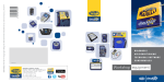
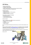
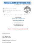
Suction Unit
F-31
Service Manual
NOTE
This manual is related to the following Equipment:
Suction Pump
F-31
Doc : Service Manual - F-31.doc Rev. 2 / 12 APR 2006
Page 1 of 12
Suction Unit
F-31
Service Manual
All equipment and accessories should be in good working order prior to use.
It is the responsibility of each facility’s engineering department to test equipments and “routine basis” to
determine if the devices are functioning within specifications.
No device or accessory should be used if a malfunction is suspected.
The installation, operation, search for breakdowns and the repair of equipment must only be performed by trained
1
personnel( ) who have sufficient knowledge about the equipment, spare parts, and the information supplied.
C AU T I O N S
B E F O R E S T AR T I N G T O I N S P E C T T H E D E V I C E , M AK E S U R E I T I S N O T C O N N E C T E D T O
THE ELECTRIC POWER SUPPLY NETWORK.
D O N O T U S E T H E AP P L I AN C E I N T H E P R E S E N C E
E X P L O S I V E L I Q U I D S , G AS E S O R M I X T U R E S .
OF
I N F L AM M AB L E
AN D / O R
D O N O T L E AV E T H E AP P L I AN C E E X P O S E D T O AT M O S P H E R I C AG E N T S O R H E AT
SOURCES.
U S I N G T H E AP P L I AN C E U N D E R D I F F E R E N T C O N D I T I O N S T H AN T H O S E S P E C I F I E D I N
T H I S H AN D B O O K M AY P R E J U D I C E I T S S AF E T Y AN D I T S T E C H N I C AL P AR AM E T E R S
DELIVERY AND UNCRATING OF UNIT
Inspect equipment and shipping crate immediately upon receipt. If any damage is apparent, you should both
report it to the trucking delivery person and contact the transportation company immediately.
Make notes of any damage on the Bill Of Lading. Retain all shipping materials for inspection. Any claims for
damage must start at the receiving point. Do not return goods without written authorization.
When submitting a claim for shipping damage, request that the carrier inspect the shipping container and
equipment.
Check packing slip carefully and make sure all materials have been received as indicated on the packing ticket.
1.
An educated (qualified) person has sufficient knowledge or experience to allow him to avoid the dangers presented by electricity, whereas an informed (trained)
person is sufficiently informed or works supervised by qualified persons, so as to allow him to avoid the dangers presented by electricity (e.g. operators or
maintenance staff).
Doc : Service Manual - F-31.doc Rev. 2 / 12 APR 2006
Page 2 of 12
Suction Unit
F-31
Service Manual
TECHNICAL SPECIFICATIONS
LENGTH
mm
450
WIDTH
mm
150
HEIGHT
mm
280
WEIGHT
kg
4,00
POWER SUPPLY
12V or 110-230V – 50/60 Hz
MAX VACUUM
bar
-0,70
MAX FLOW – WITH FILTER
l/mins
10
MAX FLOW –DIRECT MEASUREMENT ON ASPIRATION VENT
l/mins
18
BATTERY – code 05.0040
12V - 3,3AH
FUSES
A
2x1,25
ACCESSORIES INCLUDED
CODE N°
DESCRIPTION
05.0001 OR 05.0002
05.00552
05.0010
05.0016
JAR 1000 ML OR 2000 ML
SET OF TUBES
ASPIRATION PROBE CH 14 (DISPOSABLE)
ANTIBACTERIAL/HYDROPHOBIC FILTER (DISPOSABLE)
Doc : Service Manual - F-31.doc Rev. 2 / 12 APR 2006
Page 3 of 12
Suction Unit
F-31
Service Manual
BATTERY
1)
2)
The units must be recharged when not in use.
The appliance can be recharged with the appropriate external cable or by placing the appliance on the relevant
recharge stirrup.
BEFORE USING IT FOR THE FIRST TIME, IT IS NECESSARY TO KEEP BATTERIES UNDER CHARGE FOR
24 HOURS NON-STOP.
A battery that is constantly under charge lasts about 2 or 3 years.
After this period of time it is recommended to replace it.
If the appliance cannot be put under continuous recharge, recharge it for 24 hours every 15 days.
When finished using it, the device must always be recharged.
ATTENTION, THE BATTERY MAY BE DAMAGED IF NOT RECHARGED AFTER USE
The battery that is completely flat and is not immediately recharged after use must be replaced by the authorized
technical assistance.
When recharging, always make sure the warning light on the front panel is on.
WHEN ON THE DEVICE’S DISPLAY ONLY THE RED LED IS ON, WHILE THE GREEN LED AND THE TWO
YELLOW LED ARE OFF, IT IS NECESSARY TO DISCONTINUE OPERATIONS AND RECHARGE THE DEVICE.
TO CHARGE THE DEVICE, KEEP TO THE FOLLOWING INSTRUCTIONS: CONNECT THE 230/110V PLUG ON
THE BACK OF THE DEVICE, THE BLINKING LED SHALL TURN ON. SET THE SWITCH ON “CHARGE” AND
KEEP CHARGING FOR AT LEAST 12 HOURS.
THE DEVICE CAN OPERATE ON AN EXTERNAL 12 V BATTERY USING THE APPROPRIATE CABLE WITH
CAR PLUG
Battery change
C
B
A
1)
Detach the connections (A) on the blue
and brown wires
2)
Unscrew the screws (B)
3)
Raise the slab (C)
4)
Replace the battery
5)
Fix the slab (C) with the screws (B)
6)
Connect the threads verifying the
correspondence of the colors :
-
Doc : Service Manual - F-31.doc Rev. 2 / 12 APR 2006
Page 4 of 12
Blue on positive pole
Brown on negative pole
Suction Unit
F-31
Service Manual
OPERATING
The appliance is a portable SUCTION UNIT FOR EMERGENCY USE, MINOR SURGERY AND aimed at freeing
the airways from organic secretions.
OPERATIONAL TEMPERATURE: BETWEEN 0° AND 50°
RECOMMENDED RECHARGE TEMPERATURE: BETWEEN 15° AND 30°
OPERATIONAL HUMIDITY: BETWEEN 20 AND 90% RU
BEYOND 2500 METERS OF HEIGHT, THE ASPIRATION FLOW MAY DECREASE.
THE FOLLOWING STEPS ARE POSSIBLE ONLY IF THE APPLIANCE IS COMPLETELY RECHARGED
1.TIGHTLY SCREW THE LID ON THE JAR TO GUARANTEE A PERFECT SEAL
2.CONNECT THE SHORT TUBE TO FILTER 1 ON THE ‘’ASPIRATION’’ 2 VENT
3.CONNECT THE OTHER END OF THE TUBE TO THE ‘’VACUUM’’ 3 VENT WITH THE FLOAT ON THE JAR’S
LID
4.CONNECT THE LONG TUBE 4 TO THE OTHER ‘’PATIENT’’ 5 VENT ON THE JAR’S LID (VENT WITHOUT
FLOAT)
5.CONNECT THE OTHER END OF THE LONG TUBE 4 TO THE PROBE CONNECTOR 6 AND EVENTUALLY
THE SUPPLIED PROBE
7.PRESS THE ON/OFF SWITCH 7
8.ASPIRATION INTENSITY CAN BE VARIED WITH THE RELEVANT CONTROL ON THE FRONT PANEL OF
THE APPLIANCE 8 AND CAN BE CHECKED ON THE APPLIANCE FRONT PANEL 9 VACUOMETER.
9.IT IS RECOMMENDED TO CARRY OUT A FIRST ASPIRATION CYCLE WITH AT LEAST 500 ML OF WATER
ONLY.
10.THE ASPIRATED FLUID WILL FLOW IN THE RELEVANT JAR. SHOULD THE AMOUNT OF FLUID EXCEED
THE JAR’S CAPACITY, THE OVERFLOW VALVE WILL STOP ASPIRATION.
11.IMMEDIATELY SWITCH OFF THE APPLIANCE BY SETTING THE ON/OFF 7 SWITCH ON THE ‘’ OFF’’
POSITION.
Doc : Service Manual - F-31.doc Rev. 2 / 12 APR 2006
Page 5 of 12
Suction Unit
F-31
Service Manual
INDICATORS (LED)
The suction unit F-31.XX is equipped with light indicators (led) signaling the battery use, because using the
appliance on a low battery may damage the appliance itself, while continuously recharging it does not cause any
damage.
It is recommended to always check the battery’s recharge level
LIGHT INDICATOR
DESCRIPTION OF THE BATTERY LEVEL
LED ON GREEN
MAXIMUM CHARGE (2)
LED ON YELLOW
MEDIUM CHARGE (3)
LED ON YELLOW
LOW CHARGE (4)
LED ON RED
NEEDS RECHARGE (5)
LED NEXT TO THE BATTERY’S CHARGE
LEVEL INDICATORS RED
WHEN THIS LED IS ON, IT SHOWS THAT RECHARGE IS
UNDERWAY (1)
Doc : Service Manual - F-31.doc Rev. 2 / 12 APR 2006
Page 6 of 12
Suction Unit
F-31
Service Manual
PERIODIC MAINTENANCE CHECK
SUCTION UNIT WAS DESIGNED TO KEEP MAINTENANCE TO A MINIMUM. NEVERTHELESS IT IS
NECESSARY TO CARRY OUT A DAILY CHECK BEFORE USING THE APPLIANCE.
BEFORE CARRYING OUT ANY CHECK DUE TO MALFUNCTIONING OR ANOMALIES, CALL THE FAZZINI
S.R.L. TECHNICAL SERVICE OR PERSONNEL QUALIFIED BY FAZZINI S.R.L.
BATTERY CAN BE CHANGED ONLY BY TRAINED PEOPLE
FAZZINI S.R.L. DOES NOT OFFER ANY WARRANTY ON APPLIANCE THAT UPON INSPECTION BY THE
TECHNICAL SERVICE SHOWS SIGNS OF TAMPERING.
THE OPERATOR MUST EXCLUSIVELY REPLACE THE SUPPLIED ACCESSORIES IF NECESSARY IN LINE
WITH THE APPLIANCE’S USE INTENSITY
ASPIRATION TUBES SHOULD BE STERILIZED AFTER EACH USE. IN CASE OF REPAIR, THE USER
SHOULD CALL FAZZINI S.R.L. TRANSPORTATION COSTS MUST ALWAYS BE AGREED WITH FAZZINI S.R.L.
BEFORE SHIPPING FAILED PIECES.
SHOULD ANY FLUID LEAK IN THE APPLIANCE, CALL THE TECHNICAL SERVICE OF FAZZINI S.R.L. FOR
MAINTENANCE. DO NOT OPEN THE UNIT.
STORAGE
THE SUCTION UNIT MUST BE STORED IN A DRY LOCATION, PROTECTED FROM ATMOSPHERIC AGENTS
STORAGE TEMPERATURE: BETWEEN -10° AND + 55°
RELATIVE HUMIDITY BETWEEN 20 AND 80%
Doc : Service Manual - F-31.doc Rev. 2 / 12 APR 2006
Page 7 of 12
Suction Unit
F-31
Service Manual
Legenda F-31.xx
1
2
3
4
5
6
7
8
9
Doc : Service Manual - F-31.doc Rev. 2 / 12 APR 2006
Page 8 of 12
Filter
Vacuum drive
Jar drive to the filter
Disposable tube to the patient
Jar drive to the patient
Suction catheter CH 14
Main switch
Vacuum regulator
Vacuum gauge
Suction Unit
F-31
Service Manual
General assembly – F-31.xx
Doc : Service Manual - F-31.doc Rev. 2 / 12 APR 2006
Page 9 of 12
Suction Unit
F-31
Service Manual
Functional layout
Main
Wiring
Doc : Service Manual - F-31.doc Rev. 2 / 12 APR 2006
Page 10 of 12
Suction Unit
F-31
Service Manual
Pneumatic circuit
5
3
2
4
1
6
1
2
3
4
5
6
7
Doc : Service Manual - F-31.doc Rev. 2 / 12 APR 2006
Page 11 of 12
Catheter to the patient
Suction regulator
Jar
Non rebeathing valve
Filter
Pump / Motor
Vent
7
Suction Unit
F-31
Service Manual
Troobleshooting
Situation
1
Possible Cause
Solution
a
Disconnected or loose cord
Check connections and reconnect unit
b
Faulty wall outlet
Use another wall outlet
c
Fuses are damaged
Check the fuses inside SP.38.02
If fuses are damaged check the electrical insulation
on the electrical apparatus
d
Main rocker switch is damaged
In ON position, check the presence of the light ; if no
light is detected replace with a spare switch
e
Internal wiring connection are not
completed
Open the equipment and verify internal electrical wiring
(see functional layout)
Equipment will not
turn on
Charge the battery for 12 hours and check (see
indicators paragraph)
f
Situation
2
Solution
a
Vacuum regulator do not work
properly
Turn the manifold SP.21
b
Internal tubing are not properly
connected
Open the equipment and verify internal tubing
connection
c
Internal tubing are choked
Open the equipment and verify internal tubing bends
d
Pump fault
Open the equipment ,disconnect the tubing and check
the pump
Suction fault
The red light
flashes in the
on/off/charge
positions
Possible Cause
a
Situation
4
With a multimeter check the voltage between the
positive and negative pole, if the voltage value is not
around 10V dc replace the battery (see battery
paragraph)
Possible Cause
Situation
3
Battery low or battery fault
The red light is
off with SW in
the off positions
The power cable is inserted in
the main feeeding
Possible Cause
a
Doc : Service Manual - F-31.doc Rev. 2 / 12 APR 2006
Page 12 of 12
The power cable is
disconnected to the main
feeeding
Solution
The red light normally flashes in order to signal
the presence of the main feeding
Solution
The red light normally is off when the cable is
disconnected to the main feeding