1
HVAC(Heating,
Ventilation,
andAir Gonditioningl
HeatingandAir Conditioning
21-2
SpecialTools
Comoonent
Location
lndex ........z t-'5
A/CService
Tiosand
Precautions
z t-o
A,/CRefrigerant
Oil
ReDlacement
z t-o
Troubleshooting
General
lnformation
21-8
Index .......21-9
DTCTroubleshooting
SymptomTroubleshooting
1ndex..............
21-10
21-11
SystemDescription.....................
CircuitDiagram
21-14
D T CT r o u b l e s h o o t i n. .g. . . . . . . . . . .z. .t .- .t .o
Recirculation
ControlMotor
..........
CircuitTroubleshooting
21-25
HeaterControlPowerandGround
Troubleshooting
........21-27
Circuits
Condenser
FanCircuit
Troubleshooting
......................
21-28
Fans
Radiator
andCondenser
CommonCircuit
......................
21-29
Troubfeshooting
Compressor
ClutchCircuit
T r o u b l e s h o o t i n. .g. . . . . . . . . . . . . 2
. .1. .-.3. .0
A,/CPressureSwitchCircuit
......................
21-32
Troubleshooting
Air Mix ControlMotor
.............
21-34
TestandReolacement
ModeControlMotor
.............
21-35
TestandReplacement
Recirculation
ControlMotor
.............
21-36
TestandReolacement
Evaporator
Temperature
Sensor
andTest .............
21-31
Reolacement
Test .................
21-38
PowerTransistor
HeaterControlPaneland
PushSwitchAssemblv
RemovalandInstallation........21-38
DustandPollenFilter
Reolacement
..21-39
BlowerUnitRemovaland
......21-39
lnstallation
BlowerUnitComoonents
R e D l a c e m e .n. t. . . . . . . . . . . . . . . . .2. .1. .- .4. 1. . .
Evaporator
Core
..21-42
Reolacement
*HeaterUnit/Core
..21-43
ReDlacement
HeaterValveCable
.....21-46
Adjustment
..........
21-47
CompressorReplacement
21-48
Comoressor
ClutchCheck ..........
Comoressor
ClutchOverhaul.....21-49
ThermalProtector
Compressor
R e o 1 a c e m e.n. .t . . . . . . . . . . . . . . . .2. .1. .- .5. 1. . .
ReliefValve
Comoressor
R e o l a c e m e n. .t. . . . . . . . . . . . . . . . .2. .1. .- .5. 1. . .
21-52
Reolacement............
Condenser
Recovery
..................
21-53
Refrigerant
......................
21-54
SystemEvacuation
21-55
SystemCharginS.........................
21-56
LeakTest..................
Refrigerant
21-57
A,/CSvstemTests ........................
HVAC{Heating,Ventilation,and Air Conditioning)
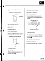
SpecialTools
Ret.No.
o
Tool Number
DescriDtion
07sAz-001000A
BackprobeSet
---2
att-,,/'Tt
e^t"'
T
21-2
KCe
"-t--'
Otv
2
Heatingand Air Gonditioning
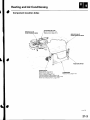
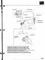
ComponentLocationIndex
VALVE
SERVICE
{LOW.PRESSUBE
SIDEI
EVAPORATOR
CORE
(Built-in
theheaterunit)
B e p l a c e m epnat ,g e2 1 4 2
SERVICE
VALVE
{HIGH-PRESSURE
SIDEI
RECEIVER/DRYER
COMPRESSOR
Beplacement,page21 47
CONOENSEB
ClutchCheck,page21-48
page 21-52
Replacement,
C l u t c hO v e r h a u lp, a g e2 1 - 4 9
ThermalProtectorCheck,page21-48
page21 51
ThermalProtectorReplacement,
R e l i eV
f a l v eR e p l a c e m e npta, g e2 1 5 1
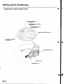
Heatingand Air Conditioning
ComponentLocationIndex(cont'dl
RADIATORFAN RELAY
Test,page22-51
CLUTCHRELAY
Tesl, page 22-51
MOTORRELAY
Test, page 22-5I
'-t
/l
l-
I
T
I
-::--
t_]]l
BOX
UNDER.HOOD
FUSE/RELAY
-
-l
-
CONDENSERFAN
Test, page 22-51
\
.\\
... A/C PRESSURE
SWITCH
-
RADIATORFAN
CONOENSERFAN
21-4
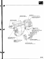
HEATER
UNIT/CORE
page21-43
Beplacement,
BLOWEN
UNIT
page21-39
Removal
andInstallation,
BLOWERUNITCOMPONENTS
page21-41
Replacement,
HEATERVALVECABLE
page21-46
Adjustment,
DUSTAND
POLLEN
FILTER
page21'39
Replacement,
RECIRCULATION
CONTROLMOTOR
Test,page21-36
page21-36
Replacement,
MODE CONTROLMOTOR
Test,page21-35
page21-35
Replacement,
POWERTRANSISTOR
Test,page 21-38
AIR MIX CONTROLMOTOR
Test,page21'34
page21'34
Replacement,
EVAPORATORTEMPERATURE
SENSOR
page 21-37
Replacement,
Test,page21-37
PUSH SWITCHASSEMBLY
Removaland Installation,page21'38
HEATERCONTROLPANEL
RemovalandInstallation,page21 38
21-5
HeatingandAir Conditioning
A/C ServiceTips and Precautions
A/C Refrigerant
Oll Replacement
R e c o m m e n d eP
d A Go i l : K E I H I NS P 1 0 :
Compressedair mixed with R-134aforms a
combustible
vapor.
T h e v a p o rc a n b u r n o r e x p l o d ec a u s i n gs e r i o u s
injury.
Never use compressedair to pressuretest
R - 1 3 4 as e r v i c ee q u i p m e not r v e h i c l ea i r
c o n d i t i o n i n sg y s t e m s .
A i r c o n d i t i o n i n gr e f r i g e r a not r l u b r i c a nvt a p o r
can irritateyour eyes,nose,or throat.
Be carefulwhen connectingserviceequipment.
Do not breatherefrigerantor vapor.
T h e a i r c o n d i t i o n i n sg y s t e mu s e sH F C - 1 3 4(aR - 1 3 4 a )
r e fr i g e r a n at n d p o l y a l k y l e n e g l y c(oPl A G )r e fr i g e r a n ot i l ,
w i t h C F C ' 1 2( R - 1 2r)e f r i g e r a n t
w h i c ha r e n o t c o m p a t i b l e
r e f r i g e r a not r m i n e r a l
l i l .D o n o t u s eR - ' 1 2
andminerao
oil in this system,and do not aftemptto use R 12
s e r v i c i n ge q u i p m e n td; a m a g et o t h e a i r c o n d i t i o n i n g
t ill result.
s y s t e mo r y o u r s e r v i c i n ge q u i p m e nw
U s eo n l y s e r v i c ee q u i p m e ntth a t i s U . L . - l i s t eadn d i s
certifiedto meet the requirementsof SAE J2210to
r e m o v eR - 1 3 4 af r o m t h e a i r c o n d i t i o n i n sg y s t e m .
lf accidentalsystem dischargeoccurs,ventilatethe
w o r k a r e ab e f o r er e s u m i n gs e r v i c e .
. P/N38897-Pl3-A01AH:'120m0 i4 fl oz)
. P/N38899-P13'A01:
40 m0 i1 1/3fl oz)
Add the recommendedrefrigerantoil in the amount
listedif you replaceany of the following parts.
. T o a v o i dc o n t a m i n a t i o nd.o n o t r e t u r nt h e o i l t o t h e
c o n t a i n eor n c ed i s p e n s e da, n d n e v e rm i x i t w i t h o t h e r
refrigerantoils.
. l m m e d i a t e la
y f'teu
r s i n gt h e o i l , r e i n s t a l l t h e
c a po n
the container,and seal it to avoid moisture
aosorpron.
. D o n o t s p i l lt h e r e f r i g e r a not i l o n t h e v e h i c l e i;t m a y
damagethe paint. lf it gets on the paint,wash it off
immediately.
, . 9l m p . o z )
C o n d e n s e r. . . . . . . . . . . 2m5A\ 5 1 6t l . o z 0
'1.4
E v a p o r a t o r. . . . . . . . .4. 5
. m0 (1113Il.oz, lmp.oz)
'10
L i n eo r h o s e . . . . . . . . . m 0 { 1 / 3f l . o z , 0 . 4l m p . o z )
'10
R e c e i v e r / D r y e.r. . . m 0 ( ' 1 1f3l . o z , 0 . 4l m p . o z )
Leakagerepair ....25 m0,1516
Il oz,0.9 lmp.oz)
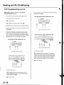
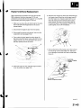
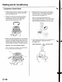
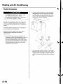
. .o rc o m p r e s s orre p l a c e m e n l ,
C o m p r e s s o r. . . . . . . F
s u b t r a ctth e v o l u m eo f o i l d r a i n e d
from the removedcompressorfrom
1 3 0m 0 ( 4 1 / 3 f l . o z4, . 6 l m p . o z )a, n d
d r a i nt h e c a l c u l a t e vdo l u m eo f o i l
'130
f rom the new compressor:
m0
i . 4 1 1 f3l . o z , 4 . 6l m p . o z ) V o l u m eo f
removedcompressor= Volume to
d r a i nf r o m n e w c o m p r e s s o r .
R - 1 3 4 as e r v i c ee q u i p m e not r v e h i c l ea i r c o n d i t i o n i n g
systemsshould not be pressuretested or leaktested
withcompressed
air.
NOTE:Evenif no oil is drainedfrom
the removedcompressor,don't
d rain more than 50 m0 \1 2/3 fl.oz,
' 1 . 8l m p
o z ) f r o mt h e n e w
compressor.
A d d i t i o n ahl e a l t ha n d s a f e t yi n f o r m a t i o nm a y b e
obtainedfrom the refrigerantand lubricant
manufacturers.
. Always disconnectthe negativecablefrom the
parts.
b a t t e r yw h e n e v e r e p l a c i n ga i r c o n d i t i o n i n g
. Keepmoistureand dirt out of the system.When
d i s c o n n e c t i nagn y l i n e s ,p l u go r c a pt h e f i t t i n g s
immediately;don't removethe caps or plugs until
iust be{oreyou reconnecteach line.
' B e f o r ec o n n e c t i n g
a n y h o s eo r l i n e ,a p p l ya f e w d r o p s
of relrigerantoil to the O-ring.
. W h e nt i g h t e n i n go r l o o s e n i n ga f i t t i n g ,u s ea s e c o n d
wrench to supportthe matchingfitting.
. W h e n d i s c h a r g i ntgh e s y s t e m u
, s ea R - ' 1 3 4 a
station;don't
refrigerantrecovery/recycling/charging
releaserefrigerantinto the atmosphere.
21-6
r\
REMOVED
COMPBESSOR
A
l i
\..
rJ
\tb
NEW
COMPRESSOR
/- a\
i
\
t
l
r /
\:)-) -/
'r:l_
_ 0L
I "o*tttu" _*lH
,lEL.-
I I I DRAINING
A: 130 m0 {4 l/3 tl.oz,4.6lmp.oz)
I voLUME
],^
\
RECEIVER
LINEA
RECEIVER/DRYER
CONDENSER
LINE
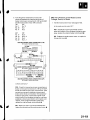
Dischargehoseto the compressor{6 x 1.0 mm) : 9.8 N.m {1.0kgf.m,7.2 lbl.ft}
Dischargehoseto the condenser(5 x 1.0mml : 9.8 N.m {1.0kgt.m,7.2 lbf ft)
Condenserline to the condenser(6 x 1.0mm) : 9.8 N.m {1.0kgf,m,7.2 lbt.ft}
Condenserfine to the receiver/dryer{6 x 1.0mm} : 9.8 N.m (1.0kgt.fi,7.2lbt.ltl
ReceiverlineAtothe receiver/dryer{6 x 1.0mm} : 9.8 N.m {1.0kgf.m. 7.2 lbf.ft}
Receiverline A to the receiveiline B : 13 N.m (1.3kgr.m,9.4 lbf.ft)
Receiverline B and the suctionline to the evaporator(6 x 1.0mm) :9.8 N.m 11.0kgf.m,7,2 lbf.ft)
Suction line to the suction hose : 3l N m {3.2 kgf.m, 23 lbf ftl
Suctionhose1o the compressor(6 x 1.0mm) : 9.8 N.m 11.0kgf.m.?.2 lbf.lt)
Compressorto the compressor b.acket {8 x 1.25 mm) : 22 N m {2.2 kgt.m, 16 lbf.ft)
Compr€ssorbracketto the engineblock {10 x 1.25mm} : ,14N.m 14.5kgf.m,33 lbf.ft)
21-7
Heatingand Air Conditioning
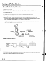
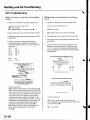
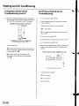
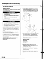
GeneralTroubleshootingInformation
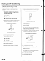
How to Retrievea DTC
The heatercontrol panel has a self-diagnosisfunction.To run the self-diagnosisfunction,do the following:
1 . T u r nt h e f a n s w i t c hO F F .
2. Pressandholdthe recirculationcontrol switch andthe rearwindow defoooerswitch down.
3 . T u r nt h e i g n i t i o ns w i t c ho N { l l i .
4. Releaseboth switches.The recirculationindicatorand the rearwindow defoggerindicatorcome on. The
recirculationindicatorgoes off 3 secondslater and the Ay'Cindicatorcomes on. then the self-diagnosiswill begin.
About 10 secondslater,the self-diagnosiswill finish and the A,/Cindicatorgoes off.
.lfanytroubleisfound.therecirculationindicatorblinksthediagnostictroublecode(DTC)toindicateafaulty
circuil or comDonent.
. lf the system is OK, the recirculationindicatorstaysoff.
atc INOICATOR
BECIRCULATION
INDICATOB
/A\
-:@
RECIRCULATION
CONTROLSWITCH
REARWINDOW
INDICATOR
OEFOGGER
@r
REARWINDOW
DEFOGGER
SWITCH
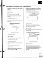
Examole of DTC indication Pattern IDTC7)
DTC 7
Recirculation +
indicatot
Recirculation+
indicalor
go6s oft
----->
Reseiting the Selt-diagnosis Function
Turn the ignition switch OFFto cancelthe self-diagnosisfunction.After completingrepairwork, run the self-diagnosis
f u n c t i o na o a i nt o m a k es u r et h a t t h e r ea r e n o o t h e rm a l f u n c t i o n s .
21-8
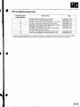
DTCTroubleshootingIndex
DTC{Recirculation
IndicationBlinks)
7
8
9
10
11
12
13
14
Detection ltem
A n o p e n i n t h e a i r m i x c o n t r o lm o t o rc i r c u i t
A short ln the air mix control motor circuit
A p r o b l e mi n t h e a i r m i x c o n t r o l i n k a q ed, o o r ,o r m o t o r
An open or shon in the mode control motor circuit
A p r o b l e mi n t h e m o d ec o n t r o l i n k a g ed, o o r s ,o r m o t o r
A p r o b l e mi n t h e b l o w e rm o t o rc i r c u i t
A problem in the EEPROMin the heatercontrol panel;
the control oanel must be reolaced
An ooen in the evaDoratortemDeraturesensorcircuit
A short in the evaDoralortemoeraturesensorcircuit
Page
( s e ep a q e2 1 - 1 6 )
( s e eD a o e2 1 - ' 1 6 )
( s e ep a q e2 1 -1 7 )
( s e eo a q e2 1 - 1 8 )
( s e ep a q e2 1 1 9 1
( s e ep a q e2 1 - 2 0 )
( s e ep a g e2 1 - 3 8 )
(seepaqe 21-23)
( s e eo a q e2 1 - 2 4 1
In case of multiple problems,the recirculationindicatorwill indicateonly the DTCwith the least number of blinks.
ln caseof an intermittentfailure,the heatercontrol panelwill storethe DTCuntil the ignition is turned off.
21-9
Heatingand Air Conditioning
\
Index
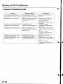
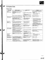
SymptomTroubleshooting
{
Also check for
Svmptom
Diagnosticprocedure
RecirculationControl Motor
Recirculationcontrol doors do not
C l e a n l i n e sasn d t i g h t n e s so f a l l
changebetweenFreshand Recirculate CircuitTroubleshooting(seepage connectors
21 251
HeaterControlPowerandGround B l o w nf u s eN o .' 1 4( 1 0 Ai)n t h e
Both heaterand Ay'Cdo not work
(see
CircuitsTroubleshooting
page21-27)
Condenserfan does not run at all (but
radiatorfan runs with the Ay'Con)
Both fans do not run with the A,/Con
Compressorclutchdoes not engage
(both fans run with A,/Con)
A/C system does not come on (both
fans and compressor)
fuse/relay
box
under-dash
Poorgroundat G501
C l e a n l i n easns dt i g h t n e sosf a l l
conneclors
. P o o rg r o u n da t G 3 0 1
. C l e a n l i n e sasn d t i g h t n e s so f a l l
connectors
R a d i a t oarn dC o n d e n s e
Fra n s
B l o w nf u s eN o . 1 ( 2 0 A )a n d N o . 4
CommonCircuitTroubleshooting (20A)in the under-hoodfuse/relay
( s e ep a g e2 1 - 2 9 )
box
P o o rg r o u n da t G 3 0 l
C l e a n l i n e sasn dt i g h t n e s so f a l l
connectors
CompressorClutchCircuit
C l e a n l i n e sasn dt i g h t n e s so f a l l
T r o u b l e s h o o t i n(qs e eD a q e2 1 - 3 0 ) connectors
Ay'CPressureSwitch Circuit
B l o w nf u s eN o . 1 ( 2 0 A )a n d N o . 4
(20A)in the under-hoodfuse/relay
T r o u b l e s h o o t i n(gs e ep a g e2 1 - 3 2 )
box
Poor ground at G301
C l e a n l i n e sasn dt i g h t n e s so f a l l
connectors
C o n d e n s eFr a nC i r c u i t
Troubleshooting{seepage 21-28)
a
\
!
21-10
a
SystemDescription
HeaterControlPanelInputsandOutputs
HEATERCONTFOLPANELCONNECIORS
CONNECTOR
A {r/rP)
CONNECTORB (22P)
W res deoitema eterm nals
CONNECTOR
Cavity
_|
Wire color
\ln Y
2
3
LT GRN
PNK/BLU
BLU
GRNA/EL
GRNA/VHT
BLUI/EL
BLU/RED
5
6
7
8
I
GRN
10
11
YEL/RED
YEVBTU
YEL/BLK
BLK
BLK/YEL
.
14
CONNECTOR
B
Cavity
Sional
AIRMIXPOTENTIAL
+5V
S E N S OC
RO M M O N
GROUND
OUTPUT
AIR MIX HOT
OUTPUT
INPUT
INPUT
INPUT
OUTPUT
INPUT
OUTPUT
OUTPUT
OUTPUT
INPUT
OUTPUT
INPUT
INPUT
A,/CPRESSURE
SWITCH
RECIRCULATE
FRESH
POWER
TRANSISTOR
BLOWERFEEDBACK
AIR MIX COOL
MODEDEF
MODEVENT
REARWINDOWDEFOGGER
RELAY
GROUND
l G 2( P o w e r )
on
Wire color
Siqnal
1
2
3
4
5
6
7
8
9
BLIVRED
--T
PNVBLK
R E A RW I N D O WD E F O G G ES
RW I T C HL E D
A./CSWITCHLED
RECIRCULATIO
CN
ONTROL
S W I T C HL E D
AIR MIX POTENTIAL
BRN
EVAPORATOR
TEIMPERATURE
SENSOR
INPUT
INPUT
INPUT
OUTPUT
OUTPUT
GAUGE
ASSEMBLY
al' 'TDr ri
LT GRN
L TG R N / B L K
10
11
14
ic
16
17
18
19
20
RED
RED/BLK
BLU
LT GRN/RED
YEVRED
YEUGRN
WHT/BLU
RED/BLU
RED/YEL
BRN^,^/HT
22
REDA/r'HT
TAILLIGHTSRELAY
INPUT
REARWINDOWDEFOGGER
SWITCH
INPUT
A/C SWITCH
RECIRCULATIO
CN
ONTROL
SWITCH
INPUT
INPUT
OUTPUT
OUTPUT
OUTPUT
OUTPUT
OUTPUT
MODE4
MODE3
M O D E2
M O D E1
I G N( P o w e d
(Not used)
(cont'd)
21-11
Heatingand Air Gonditioning
SystemDescription(cont'dl
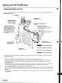
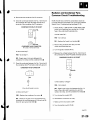
The air conditioningsystem removesheatfrom the passengercompartmentby circulatingrefrigerantthrough the
system as shown below.
BLOWER
FAN
\
\
\ r\,u
/
EXPANSIONVALVE
(Metersthe required
amount of refrigerant
into the evaporator)
APOBATORTEMPERATURE
SENSOR
THERMALPROTECTOR
(Opensthe compressorclutchcircuit
when the compressottemperature
becomestoo high)
A/C PRESSURESWITCH
When the refriqerantis below
196kPa(2.0kgi/cm',28psi)
or above3,140kPa(32 kgf/cm'
455 psi),the Py'cpressure
switchopensthe circuitto
the Py'Cswitch and stopsthe
air conditioningto protectthe
compressor-
RELIEF
VALVE
(Relieves
pressure
at thecompressor
w h e nt h ep r e s s u ri e
st o oh i g h )
A/C COMPRESSOR
(Suctionand comoression)
RECEIVER/DRYER
(Trapsdebris,and
\-^
removesmorsturel
/CONDENSER
(Radiationof heat)
I
vAPoR
HrcHPRESSURE
-:--l
[ '....
Low PREsSUBE
LrourD
tffi
Low PREssURE
vAPoR
refrigerantwhich does not containchlorofluorocarbons.Pay attentionto the
This vehicleuses HFC-134a(R-'134a)
following serviceitems:
. D o n o t m i x r e f r i g e r a n tCs F C - 1 2
( R - 1 2a) n d H F C - 1 3 4(aR - 1 3 4 aT) .h e ya r e n o t c o m p a t i b l e .
'!0)
. U s eo n l y t h e r e c o m m e n d e p
d o l y a l k y l e n e g l y c(oPl A G) r e f r i g e r na t o i l ( K E l H l NS P
designedfortheR-134a
(PAG)
recommended
refrigerant
with
retrigerant
oil will resultin
compressor.Intermixingthe
oil
any other
compressorfailure.
. AllAy'Csystem parts (compressor,dischargeline, suction line,evaporator,condenser,receiver/dryer.
expansion
valve,O-ringsfor joints) have to be designedfor refrigerantR 134a.Do not exchangewith R-'12parts.
. Use a halogengas leakdetectordesignedfor refrigerantR-134a.
. R-12and R-134arefrigerantservicingequipmentare not interchangeable.
Use only a recovery/recycling/charging
s t a t i o nt h a t i s U . L . - l i s t eadn d i s c e r t i f i e dt o m e e tt h e r e q u i r e m e n tosf S A EJ 2 2 1 0t o s e r v i c eR - 1 3 4 a i r c o n d i t i o n i n g
system.
. Always recoverthe refrigerantR-134awith an approvedrecovery/recycling/charging
stationbeforedisconnecting
any Ay'Cfifting.
21-12
HeatingandAir Conditioning
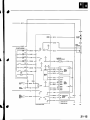
GircuitDiagram
UNDEN
rcODFUSVRELIYSOX
UNOER
DASN
fUSE/8EIlYBOX
|GNUION
SWTCfi
lG2HoI ii 0l\lllll
+.
\
C}F
rG2/
BLK/RED
l
;
.I
/
Y
I
\ IHEFMAI
PBorEcro8 I
I
*n*,*,
lTl
| <l I CLUTCH
tf
_l
.
G301
MUITIPLD(
CONTFOI
UNITI
-!10.
T
RADIATOS\ NADIATOS
) tAl'/
/ swtlcll
oT0n
I
B LX
I
G301
21-14
j
19S"F
193"C) l
I
I
n
A/CPnESSUEt
swTOt
irgF 8Ll
T
t...iCF
BLU
CONDEN$N
MOTOB
I
I
8u(
I ilnthoundor dasiluse/lelay
box
-
BU/YEL
-8lU/wH'I
EVAPORATOB
TEMPERATUNESENSOR
sn 4-Lrenil
m
::-:::: ., . a/c
YEUBLU
YEL/NED
M DEF
MODEl
BED/YEI
Mq)EI
RED/8LU
M00€2
M00t3
WHT/8LU
MOOE3
YEL/GRN
MOOEI
M00l
co TnoL
MOTOS
s
LTGRI'l
ffftH,,
F*u,*
GNNMHT
8U
I
GRN/YEL
8LK--..-...-l
(
f
coNNEcroFrir.Pt
mxr{EcroB
! {2P)
G5'1
G602
21-15
Heatingand Air Conditioning
DTCTroubleshooting
DTC7:An Openin theAir Mix ControlMotor
Circuit
DTC8:A Shortin theAir Mix ControlMotor
Circuit
1. Test the air mix control motor {seepage 2'l-341.
1. Testthe air mix control motor(see page 21-341.
ls the air mix control motor OK?
YES-Go to step 2.
N O - R e p l a c et h e a i r m i x c o n t r o lm o t o r . l
2. Disconnectthe air mix control motor 5P connector.
3. Disconnectheatercontrol panel connectorsA {14P)
a n dB ( 2 2 P ) .
4. Checkfor continuitybetweenthe following
terminalsof heatercontrol panel connectorsA
(14P)and B (22P)and the air mix control motor 5P
connector,
14P:
5P:
No.5
N o .1
No.4
No.2
No.2
No.3
N o .1
No.9
ls the ait mix control motor OK?
YES-Go to step 2.
NO-Replace the air mix contorol motor.I
2. Disconnectthe air mix control motor 5P connector.
3. Disconnectheatercontrol panelconnectorsA (14P)
andB (22P).
4. Checkfor continuitybetweenbody ground and
heatercontrol panelconnectorA (14P)terminals
No. 1, 2, 3, and 9 individually,and betweenbody
ground and heatercontrol panelconnectorB (22P)
t e r m i n a lN o . 6 .
A {I4PI
HEATERCONTROL
PANELCONNECTOR
22P:
No.6
5P:
No.3
W i r e s i d eo f f e m a l et e r m i n a l s
HEATERCONTFOL PANELCONNECTORB I22P1
Wire side ol lem.letehi.6ls
ls there continuity?
YES-Check for loosewires or poor connectionsat
heatercontrol oanel connectorsA (14P)and B (22P)
and at the air mix control motor 5P connector.lf the
connectionsare good. substitutea known-goodair
mix control motor, and recheck,lf the symptom/
indicationgoes away, replacethe originalair mix
control motor. lf the symptom/indicationcontinues,
substitutea known-goodheatercontrol panel,and
recheck.lf the symptom/indicationgoes away,
replacethe original heatercontrol panel.l
N O R e p a i ra n y o p e n i n t h e w i r e ( s )k e t w e e n t h e
heatercontrol panel and the air mix control
motor.l
21-16
W i r e s i d eo i l e m a e l e r m i n a l s
ls therc continuity?
Y E S - R e p a i ra n y s h o r t t o b o d y g r o u n dl n t h e
wire(s)betweenthe heatercontrol panel and the air
mix control motor.l
N O - G o t o s t e p5 .
5. Turn the ignition switch ON (ll),and checkthe same
terminalsfor voltage.
HEATERCONTROLPANELCONNECTOR
A {14PI
DTC9: A Problemin the Air Mix Control
Linkage,
Door,or Motor
1, Test the air mix control motor (seepage 21-34).
ls the air mix control motor OK?
YES-Substitute a known-goodheatercontrol
panel,and recheck.lf the symptom/indicationgoes
away, replacethe original heatercontrol panel.l
NO-Replace the air mix control motor, or repair
t h e l i n k a g ea n d d o o r . l
Wire side of femaleterminals
HEATERCONTROLPANELCONNECTOR
B I22PI
Wiresideof femaleterminals
ls there any voltage?
YES-Repair any short to power in the wire(s)
betweenthe heatercontrol panel and the air mix
control motor. This short may also damagethe
heatercontrol panel.Repairthe short to power
before replacingthe heatercontrol panel.l
NO Substitutea known-goodair mix control
motor, and recheck.lf the symptom/indicationgoes
away, replacethe originalair mix control motor. lf
the symptom/indicationcontinues,substitutea
known-goodheatercontrol panel,and recheck.lf
the symptom/indicationgoes away, replacethe
originah
l e a t e rc o n t r o lp a n e l . I
21-17
Heatingand Air Conditioning
DTCTroubleshooting.(cont'd)
DTC10:An Openor Shortin the Mode
ControlMotorCircuit
1. Test the mode control motor (seepage 21-35).
5 . T u r nt h e i g n i t i o ns w i t c hO N ( l l ) ,a n d c h e c kt h e s a m e
t e r m i n a l sf o r v o l t a g e .
HEATEB
CONTROL
PANEL
CONNECTOR
A {14P)
ls the mode cottol motor OK?
YES Go to step 2.
NO Replacethe mode control motor.I
2. Disconnectthe mode control motor 10Pconnector.
s (14P)
3 . D i s c o n n e cht e a t e rc o n t r o lp a n e lc o n n e c t o r A
and B \22P1.
Checkfor continuitybetweenbody ground and
h e a t e rc o n t r o lp a n e lc o n n e c t oA
r ( 1 4 P t)e r m i n a l s
N o . 2 , 1 0 ,a n d 1 1 i n d i v i d u a l l ya,n d b e t w e e nb o d y
g r o u n da n d h e a t e rc o n t r o lp a n e lc o n n e c t o B
r (22P)
'17,
1 8 ,1 9 ,a n d 2 0 i n d i v i d u a l l y .
t e r m i n a l sN o .
HEATER
CONTROL
PANEL
CONNECTOR
A {14PI
Wire side of femaleterminal
HEATERCONTROLPANELCONNECTOR
B {22PI
3
tl
12
5
X
15 T6
6
1 1 1 8 t 9 2A 21 22
RED/YEL
WHT
Wiresideof femaleterminals
Wire side ol lemale terminals
HEATERCONTROLPANELCONNECTOR
B {22P)
ls there any voltage?
YES-. Repairany short to power in the wire(s)
betweenthe heatercontrol panel and the mode
control motor. This short may also damagethe
heatercontrol panel.Repairthe short to power
before replacingthe heatercontrol panel.l
NO- Go to step 6.
W i r e s i d e o f f e m a L el e r m i n a l s
ls there continuity?
Y E S R e p a i ra n y s h o r t t o b o d y g r o u n di n t h e
wire(s)betweenthe heatercontrol panel and the
mode control motor.l
NO
21-18
Go to step 5.
Turn the ignition switch OFF,and checkfor
continuitybetweenthe following terminalsof
heatercontrol panel connectorsA (14P)and B (22P)
and the mode control motor 10Pconnector.
14P:
10P:
'10
N o .2
No.
No.10
No,1
N o .1 1
No.2
22P:
N o .1 7
N o .1 8
No.19
N o .2 0
10P:
No.8
No.6,9
No.5
N o .4 , 7
DTC11:A Problemin the ModeControl
Linkage,
Doors,or Motor
1. Testthe mode control motor (seepage 21-35).
ls the mode control motor OK?
YES Substitutea known-goodheatercontrol
panel,and recheck.lf the symptom/indicationgoes
away, replacethe original heatercontrol panel.l
NO Replacethe mode control motor, or repairthe
l i n k a g ea n d d o o r s . l
HEATER
PANELCONNECTOR
A (14PI
CONTROL
Wiresideof lemaleterminals
MODECONTROLMOTORlOPCONNECTOR
Wiresideof femaleterminals
HEATERCONTROLPANELCONNECTORB {22PI
Wire side of femaleterminals
ls there continuity?
YES-Check for loosewires or poor connectionsat
heatercontrol panelconnectorsA (14P)and B (22P),
and at the mode control motor 10Pconnector.lf the
connectionsare good, substitutea known-good
mode control motor, and recheck.lf the symptom/
indicationgoes away. replacethe original mode
control motor.lfthe symptom/indicationcontinues,
substitutea known-goodheatercontrol panel,and
recheck.lf the symptom/indicationgoes away,
replacethe originalheatercontrol panel.l
NO Repairany open in the wire(s)betweenthe
heatercontrol Daneland the mode control motor.l
21-19
HeatingandAir Gonditioning
DTCTroubleshooting{cont'd)
DTC12:A Problemin the BlowerMotor
Circuit
'1.
C h e c kt h e N o . 1 2 ( 4 0 A ) f u s ei n t h e u n d e r - h o o d
fuse/relaybox, and the No. 14 (10A)fuse in the
under-dashf use/relaybox.
7. Checkfor continuitybetweenthe No. 3 terminal of
the power transistor4P connectorand body ground.
POWERTRANSISTOR4P CONNECTOR
2
Are the tuses OK?
3
o
NO Replacethe fuse(s),and recheck.l
2. Connectthe No. 2 terminal of the blower motor 2P
connectorto body ground with a jumper wire.
BLOWERMOTOB2PCONNECTOR
4
BLK
YES-Go to step 2.
Wire side ol temaleterminals
ls there continuity?
YES-Go to step 8.
JUMPER] BLU/BLK
NO-Check for an open in the wire betweenthe
power transistorand body ground. lf the wire is OK,
checkfor poor ground at G502.I
8 . Connectthe No. 1 and No. 3 terminalsof the power
transistor4P connectorwith a jumper wire.
Wiresideol femaleterminals
TRANSISTOR
4PCONNECTOR
POWER
3 . T u r nt h e i g n i t i o ns w i t c hO N ( l l ) .
Does the blowet motor run?
YES Go to step 4,
NO Go to step 17.
4. Turn the ignition switch OFF.
Wiresideof femaleterminals
5. Disconnectthe jumper wire.
6. Disconnectthe power transistor4P connector.
9 . T u r nt h e i g n i t i o ns w i t c hO N ( l l ) .
Does the blower motor tun at high speed?
Y E S - G o t o s t e p1 0 .
NO-Repair open in the wire betweenthe power
transistorand the blower motor.l
1 0 . Turn the ignition switch OFF.
1 1 . Disconnectlhe jumper wire.
21-20
1a
Disconnectheatercontrol panelconnectorA (14P).
1 3 .Checkfor continuitybetweenthe No. 7 and No. 8
terminalsof heatercontrol panel connectorA (14P)
a n d b o d y g r o u n di n d i v i d u a l l y .
HEATER
CONTNOL
PANEL
CONNECTOR
A {14PI
1 5 . Reconnectheatercontrol panel connectorA (14P).
lo.
Test the power transistor(seepage 21-38).
ls the power transistorOK?
YES Checkfor loosewires or poor connectionsat
heatercontrol panel connectorA (14P)and at the
power transistor4P connector.lf the connections
are good, substitutea known-goodheatercontrol
panel,and recheck.lf the symptom/indicationgoes
away, replacethe original heatercontrol panel.l
NO
Replacethe power transistor.I
1 7 . Disconnectthe jumper wire.
1 8 . Disconnectthe blower motor 2P connector.
1 9 . Measurethe voltagebetweenthe No, 1 terminal of
the blower motor 2P connectorand body ground.
ls there continuity?
YES Repairany shortto body ground in the
wire(s)betweenthe heatercontrol panel and the
power transistor.I
BLOWERMOTOR2PCONNECTOR
BLU/WHT
NO Go to step 14,
1 4 . Checkfor continuitybetweenthe following
terminalsof heatercontrol panelconnectorA ( 14P)
and power transistor4P connector.
'l4Pt
4P:
No.4
No.7
No.8
No.2
HEATER
CONTROL
PANEL
CONNECTOR
A (14P)
Wiresideof femaleterminals
Wire side ot femaleterminals
z 3
I
T 8
9
4 1 5 1 6
r ol x l I
ls thete battery voltage?
1 2 l1 3l 1 4
BLU/YEL
YES- Replacethe blower motor.l
)
8LU/RED
NO Go to step 20.
20. Turn the ignitionswitch OFF.
ILU/YEL
4PCONNECTOR
POWER
TRANSISTOR
Wiresideof femaleterminals
2 1 .Removethe blower motor relayfrom the underhood fuse/relaybox, and test it (seepage 22-511.
ls the relay OK?
ls thete continuity?
YES Go to step 22.
YES Go to step 15.
NO- Replacethe blower motor relay.l
NO Repairany open in the wire(s)betweenthe
heatercontrol paneland the power transistor.l
(cont'd)
21-21
Heatingand Air Conditioning
DTCTroubleshootinglcont'd)
22. Measurethe voltage betweenthe No. 3 terminal of
the blower motor relay 4P socketand body ground.
25. Turn the ignition switch OFF,
26. Checkfor continuitybetweenthe No. 1 terminal of
the blower motor relay 4P socketand body ground.
BLOWERMOTORRELAY4PSOCKET
2
4
1
BLOWERMOTORRELAY4PSOCKET
3
ls there battety voltage?
YES-Go to step 23.
ls there continuity?
NO Replacethe under-hoodfuse/relaybox.t
YES-Repair open in the BLUIr'/HTwire between
the blower motor relay and the blower motor.l
23. Turn the ignitionswitch ON {ll).
Measurethe voltage betweenthe No. 2 terminal of
the blower motor relay 4P socketand body ground,
BLOWERMOTORRELAY4PSOCKET
ls therebattery voltage?
YES-Go to step25.
NO Repairopenin thewire betweenthe No.14
fusein the under-dash
fuse/relay
boxandthe
blowermotorrelay.I
21-22
NO Checkfor an open in the wire betweenthe
blower motor relay and body ground. lf the wire is
O K ,c h e c kf o r p o o r g r o u n da t G 3 0 1 . 1
\
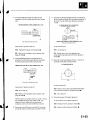
DTC14:An Openin the Evaporator
Temperature
SensorCircuit
1. Removethe evaporatortemperaturesensor(see
p a g e2 1 - 3 7 ) .
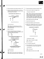
2. Measurethe resistancebetweenthe No. l and
No. 2 terminalsof the evaporatortemperature
sensor.
x D i pt h e s e n s o ri n i c ew a t e r ,a n d m e a s u r e
resistance.Then pour hot water on the sensor,and
c h e c kf o r c h a n g ei n r e s i s t a n c e .
4. Checkfor continuitybetweenthe No. 7 terminal of
heatercontrol panelconnectorB (22P)and the
No. 1 terminal of the evaporalortemperature
s e n s o r2 P c o n n e c t o r .
B {22P)
HEATERCONTROLPANELCONNECTOR
Wiresideof femaleterminals
EVAPORA
TORTEMPERATURE
SENSOR
ll#l
t-l
SENSOR
2PCONNECTOR
EVAPORATOR
TEMPERATURE
Wiresideof femaleterminals
lI UT-TU
l , l , l l
---r---T--I
t
^
11c))-l
ls there continuity?
\9/
T e r m i n asl i d eo f m a l et e r m i n a l s
YES Go to step 5.
NO Repairopen in the wire betweenthe heater
control panel and the evaporatortemperature
sensor.I
5. Disconnectheatercontrol panelconnectorA (14P).
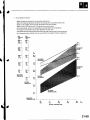
RESISTANCE
k0
50
10
68
20
86'F
30'c
TEMPERATURE
ls the tesistancewithin the specificationsshown
on the graph?
Y E S - G o t o s t e p3 .
NO Replacethe evaporatortemperature
sensor.I
3. Disconnectheatercontrol panelconnectorB {22P).
(cont'd)
21-23
Heatingand Air Gonditioning
DTCTroubleshooting{cont'd)
6. Checkfor continuitybetweenthe No. 2 terminal of
heatercontrol panel connectorA (14P)and the
No, 2 terminal of the evaporalortemperature
sensor2P connector.
HEATER
CONTROL
PANELCONNECTOR
A {14PI
Wiresideof femaleterminals
LT GRN
DTC15:A Shortin the Evaporator
Temperature
SensorCircuit
1. Removethe evaporatortemperaturesensor(see
p a g e2 1 - 3 7 ) .
2. Testthe evaporatortemperaturesensor(seepage
21-37J.
ls the resistance within the specifications shown
on the graph?
YES Go to step 3.
NO Replacethe evaporatortemperature
sensor.!
EVAFORATOR
TEMPERATURE
SENSOR
2PCONNECTOR
Wiresideof femaleterminals
Disconnectheatercontrol panel connectorB l22Pl.
4. Checkfor continuitybetweenthe No. 7 terminal of
ls there continuity?
YES-Check for loosewires or Doorconnectionsat
heatercontrol panel connectorA ('l4P)and B l22Pl
and at the evaporatortemperaturesensor2P
connector.lf the connectionsare good, substitutea
known-goodheatercontrol panel,and recheck.lf
the symptom/indicationgoes away, replacethe
original heatercontrol panel.l
heatercontrol panel connectorB {22P)and body
ground.
HEATER
CONTROL
PANELCONNECTOR
B (22P)
\
NO Reoairooen in the wire betweenthe heater
control panel and the evaporatortemperature
sensor.I
Wire side of femaleterminals
ls there continuity?
YES Repairshort to body ground in the wire
betvveenthe heatercontrol paneland the
evaporatortemperaturesensor.I
NO-Substitute a known-goodheatercontrol panel,
and recheck.lf the symptom/indicationgoes away,
replacethe original heatercontrol panel.I
21-24
RecirculationControlMotor CircuitTroubleshooting
1 . C h e c kt h e N o . 1 4 ( ' 1 0 A ) f u sien t h e u n d e r - d a s h f u s e /
relay box.
8. Checkfor continuitybetweenthe No. 5 and No. 6
terminalsof heatercontrol panelconnectorA (14P)
and body ground individually.
ls the f use OK?
YES Go to step 2.
A I14P)
HEATER
CONTROL
PANELCONNECTOR
NO- Replacethe fuse, and recheck.l
2. Disconnectthe recirculationcontrol motor 5P
conneclor.
3 . Turn the ignitionswitch ON (ll).
lvleasurethe voltage betweenthe No. 5 terminal of
the recirculationcontrol motor 5P connectorand
body ground.
RECIRCULATIONCONTROLMOTOR
5P CONNECTOR
Wire side of femaleterminals
ls there continuity?
YES Repairany shortto body ground in the
wire(s)betweenthe heatercontrol panel and the
recirculationcontrol motor.l
NO-Go to step 9.
9. Turn the ignition switch ON (ll),and checkthe same
wires for voltage.
Wiresideof femaleterminals
A Il4PI
PANELCONNECTOR
HEATER
CONTROL
ls there battery voltage?
YES Go to step 5.
NO- Repairopen in the wire betweenthe No. 14
fuse in the under-dashfuse/relaybox and the
recirculationcontrol motor .l
5 . Turn the ignitionswitch OFF.
6 . Testthe recirculationcontrol motor {seepage 2136),
ls the recirculationcontrol motor OK?
YES Go to step 7.
NO- Replacethe recirculationcontrol motor, or
r e p a i rt h e l i n k a g ea n d d o o r s . I
7 . Disconnectheatercontrol panel connectorA (14P).
Wiresideof lemaleterminals
ls therc any voltage?
Y E S R e p a i ra n y s h o n t o p o w e ri n t h e w i r e ( s )
betweenthe heatercontrol panel and the
recirculationcontrol motor. This shon may also
d a m a g et h e h e a t e rc o n t r o lp a n e l .R e p a i rt h e s h o n
to power before replacingthe heatercontrol
p an e l .I
N O - G o t o s t e p1 0 .
{cont d r
21-25
Heatingand Air Conditioning
RecirculationControl Motor CircuitTroubleshooting(cont'd!
10. Turn the ignition swirchOFF.
11. Checkfor continuitybetweenthe following
terminalsof heatercontrol panel connectorA ( 14P)
and the recirculationcontrol motor 5P connector.
'l4Pt
5P:
No.5
N o .1
No.6
No.2
HEATER
CONTROL
PANEL
CONNECTOR
A {14P}
Wiresideol temaleterminats
RECIRCULATION
CONTROL
MOTOR5PCONNECTOR
Wiresideol lemaleterminals
ls there continuity?
YES Checkfor loosewires or poor connectionsat
heatercontrol panel connectorA ( 14P)and at the
recirculationcontrol motor 5P conneclor.lf the
connectionsare good, substitutea known-good
heatercontrol panel,and recheck.lf the symptom/
indicationgoes away, replacethe original heater
control panel,I
NO Repairany open in the wire{s)betweenthe
heatercontrol panel and the recirculationcontrol
motor.l
21-26
HeaterControlPowerand GroundCircuitsTroubleshooting
1 . C h e c kt h e N o . 1 4( 1 0 A ) f u s ei n t h e u n d e r - d a s h
fuse/relaybox.
6. Checkfor continuitybetweenthe No. l3terminal of
heatercontrol panelconnectorA (14P)and body
g round.
ls the f use OK?
A (1ilP)
HEATER
CONTRoLPANELCONNEcToR
YES-Go to step 2.
N O - R e p l a c et h e f u s e ,a n d r e c h e c k . l
2. Disconnectheatercontrol panelconnectorA{'14P).
1 2 3
I
8 9
4 5 6
r0t, 1 l 12
.o
3. Turn the ignition switch oN (ll).
4. Measurethe voltage betweenthe No. l4terminal
of heatercontrol panelconnectorA (14P)and body
grouno.
A {14P}
PANELCONNECTOR
HEATER
CONTROL
2 3
7 8 I 1 0l ,
4
11 12
14
BLK
5 6
14
BLK/YEL
Wire side of temaleterminals
Wire side of temaleterminals
ls therc continuity?
YES Checkfor loosewires or poor connectionsat
healercontrol panel connectorA (14P).lfthe
connectionsare good, substitutea known-good
heatercontrol panel,and recheck.lf the symptom/
indicationgoes away, replacethe original heater
control panel.l
NO Checkfor an open in the wire betweenthe
heatercontrol paneland body ground. lf the wire is
O K ,c h e c kf o r p o o r g r o u n da t G 5 0 1I.
ls there battery voltage?
YES-Go to step 5.
NO Repairopen in the wire betvveenthe No. 14
fuse in the under-dashfuse/relaybox and the
heatercontrol panel.l
Turn the ignitionswitch OFF.
21-27
Heatingand Air Conditioning
CondenserFanCircuitTroubleshooting
NOTE:lf neitherthe condenserfan nor the radiatorfan
work, go to Radiatorand CondenserFansCommon
CircuitTroubleshooting(seepage21-29).
1. Checkthe No. 1 (20A)fuse in the under-hood
f u s e / r e l a yb o x ,a n d t h e N o . 1 4 ( 1 0 A ) f u s ei n t h e
under-dashf use/relaybox.
4 . C o n n e ctth e N o . l a n d N o . 2 t e r m i n a l s o f t h e
condenserfan relay 4P socketwith a jumper wire.
CONDENSERFAN RELAYitP SOCKET
Are the tuses OK?
JUMPERWIRE
YES-Go to step 2.
NO Replacethe fuse(s),and recheck.t
2. Removethe condenserfan relayfrom the
under-hoodfuse/relaybox, and test it
( s e ep a g e2 2 - 5 1 ) .
Does the condenser lan tun?
ls the relay OK?
YES-Go to step 5.
YES Go to step 3.
NO Go to step8.
NO- Replacethe condenserfan relay.l
5. Disconnectthe jumper wire.
3. Measurethe voltage betweenthe No, 2 terminal of
the condenserfan relay 4P socketand body ground.
CONDENSERFAN RELAYilP SOCKET
6. Turn the ignition switch ON (ll).
7. Measurethe voltage betweenthe No, 3 terminal of
the condenserfan relay 4P socketand body ground.
CONDENSER
FAN FELAY4PSOCKET
r-,_-l
1
2 |
Flr
\----1--rl
IELK/YEL
d,
ls thete battery voltage?
I
YES-Go to step 4.
ls there battery voltage?
NO-Replace the under-hoodfuse/relaybox.l
YES Replacethe under-hoodfuse/relaybox.t
N O - R e p a i r o p e ni n t h e w i r e b e t w e e nt h e N o . 1 4
fuse in the under-dashfuse/relaybox and the
c o n d e n s efra n r e l a y . l
Disconnectthe jumper wire.
21-28
Radiatorand CondenserFans
CommonCircuitTroubleshooting
9 . Disconnectthe condenserfan 2P connector,
1 0 .Checkfor continuitybetweenthe No. 1 terminal of
the condenserfan relay 4P socketand the No. 2
terminal of the condenserfan 2P connector.
CONDENSER
FANRELAY4PSOCKET
NOTE;lf both fans and the Ay'Ccompressorclutchdo
not work when the Ay'Cswitch is on, go to Ay'CPressure
Switch CircuitTroubleshooting(seepage 21-32l,.
1. Checkthe No. 1 {20A}and No. 4 (20A)fuses in the
under-hoodfuse/relaybox, and the No. 14 (10A)
fuse in the under-dashfuse/relaybox.
Are the tuses OK?
YES Go to steD2.
NO Replacethe fuse(s),and recheck.l
CONDENSERFAN 2P CONNECTOR
Wire side of femaleterminals
2. Removethe condenserfan relavfrom the
under-hoodf use/relaybox.
3 . T u r nt h e i g n i t i o ns w i t c hO N ( l l ; .
Is there continuity?
4. Measurethe voltage betweenthe No. 3 terminal of
the condenserfan relay 4P socketand body ground.
YES Go to step 11.
NO- Repairopen in the wire betweenthe
c o n d e n s efra n r e l a ya n d t h e c o n d e n s efra n , I
'11.
Checkfor continuitybetweenthe No. 1 terminal of
the condenserfan 2P connectorand body ground.
FAN2PCONNECTOR
CONDENSER
2
1
-l
r-,
FANRELAY4PSOCKET
CONDENSER
1
2 l
f---r---
l,l,l
lar-vverl
oI
BLK
o
ls there battery voltage?
YES Go to step 5.
Wire side of {emaleterminals
ls there continuity?
NO Repairopen in the wire betweenthe No. 14
fuse in the under-dashfuse/relaybox and the
radiatorfan relay,and the condenserfan relay.l
YES- Replacethe condenserfan motor.I
5. Turn the ignition switch OFF.
NO Checkfor an open in the wire betweenthe
condenserfan and body ground. lf the wire is oK,
c h e c kf o r p o o rg r o u n da t G 3 0 1 . 1
l e c o n d e n s efra n r e l a y .
6 . R e i n s t a tl h
7 . M a k es u r et h e I V Cs w i t c hi s O F F .
8 . T u r nt h e i g n i t i o ns w i t c hO N ( l l ) .
(cont'd)
21-29
HeatingandAir Conditioning
Radiatorand CondenserFans
CommonCircuitTroubleshooting
(cont'dl
9. Using a BackprobeSet, measurethe voltage
betweenthe No. 6 terminal of ECN4
connectorB
{24P)and body ground with the ECMconnectors
connecteo.
ECMCONNECTOR
B {24P}
CompressorClutchCircuit
Troubleshooting
1. Checkthe No. 1 (20A)fuse in the under-hood
f u s e / r e l a yb o x ,a n dt h e N o . 1 4 { 1 0 A ) f u s ei n t h e
under-dashfuse/relaybox.
Are the tuses OK?
YES Go to step 2.
NO Replacethe fuse(s),and recheck.I
2. Checkthe enginecoolanttemperature,the throttle
positionsensor,and the idle speed (usethe Honda
PGMTesterPGM-Fldata list if possible).
ls the coolant temperaturc above nomal, the
throttle position sensor rcading too high, or the
idle speed too low?
Wire side of femaleterminals
ls there battery voltage?
YES UDdatethe ECM if it does not have the latest
so{tware,or substitutea known-goodECM,then
recheck(seepage 11-6).lf the symptom/indication
goes away with a known-goodECM,replacethe
originaE
l CM.I
NO Repairopen in the wire betweenthe radiator
fan relay,the condenserfan relay and the ECM.t
YES Troubleshootand repairthe causeof the
high enginecoolanttemperature,high throttle
positionsensor reading,or low idle speed.l
NO-Go to step 3.
3. Removethe compressorclutchrelay from the
under-hoodfuse/relaybox, and test it (seepage 225 1) .
ls the relay OK?
YES Go to step 4.
NO Replacethe compressorclutch relay.I
4. Measurethe voltage betweenthe No. 2 terminal of
the compressorclutch relay 4P socketand body
ground.
COMPfiESSON
CLUTCHBELAY'P SOCKET
ls there battery voltage?
YES Go to step 5.
NO Replacethe under-hoodfuse/relaybox.I
21-30
\
5. Connectthe No. 1 and No. 2 terminalsof the
compressorclutch relay 4P socketwith a jumper
wire.
COMPRESSORCLUTCHRELAY4P SOCKET
L Turn the ignition switch OFF.
10. Reinstallthecompressorclutch relay.
11. l\4akesure the Ay'Cswitch is OFF.
1 2 . T u r nt h e i g n i t i o ns w i t c hO N { l l ) .
JUMPERWIRE
13. Uslng the BackprobeSet, measurethe voltage
betweenthe No. 18 termina!of ECI\4connector
E {31P)and body ground with the ECMconnectors
connected.
ECMCONNECTOR
E 131P}
2
3 t 4 5
6
1
1 4 1 5 16
Does the compressor clutch click ?
22 23 24
26
27
E
9
m
21
29
31
RED
YES Go to step 6.
N O - G o t o s t e p1 4 .
6. Disconnectthe jumper wire.
Wire side of femaleterminals
7 . T u r nt h e i g n i t i o ns w i t c hO N ( l l ) .
ls there battery voltage?
8. Measurethe voltagebetweenthe No. 3 terminal of
the compressorclutch relay 4P socketand body
ground.
COMPRESSOR
CLUTCHRELAY4PSOCKET
YES Updatethe ECM if it does not have the latest
software,or substitutea known-goodECM,then
recheck(seepage 11-6).lf the symptom/indication
goes away with a known-goodECIM,replacethe
o r i g i n aE
l CM.I
NO Repairopen in the wire betweenthe
c o m p r e s s ocr l u t c hr e l a ya n d t h e E C M . I
1 4 . D i s c o n n e ct h
t e j u m p e rw i r e .
15. Disconnectthe compressorclutch lPconnector.
ls there battery voltage?
YES-Go to step 9.
NO Repairopen in the wire betweenthe No. 1 4
fuse in the under-dashfuse/relaybox and the
compressorclutch relay,I
{cont'd)
21-31
Heatingand Air Conditioning
Compressor
ClutchCircuit
Troubleshooting(cont'dl
16. Checkfor continuitybetweenthe No. lterminal of
the compressorclutch relav 4P socketand the No. l
terminal of the compressorclutch 1Pconneclor.
COMPRESSON
CLUTCHRELAY4PSOCKET
A/C PressureSwitch Circuit
Troubleshooting
'1.
Turn the ignition switch ON {ll).
2. Turn the blower switch on, and checkfor blower
motor operatron.
Does the blower motor run on all speeds?
YES Go to step 3.
NO Troubleshootthe blower motor circuit(see
page21-20).
3. Turn the ignition switch OFF.
4. Disconnectheatercontrol panelconnectorA ('14P).
COMPRESSORCLUTCH1P CONNECTOR
Terminalside of male terminals
ls therc continuity?
YES-Check the compressorclutchclearance,the
thermal protector,and the compressorclutchfield
c o i l ( s e ep a g e2 1 - 4 8 ) . I
5 . T u r nt h e i g n i t i o ns w i t c hO N ( l l ) .
6. Measurethe voltage betweenthe No, 4 terminal of
heatercontrol panelconnectorA {14P)and body
ground.
HEATER
CONTROL
PANELCONNECTOR
A (I4P}
NO-Repair open in the wire betweenthe
compressorclutch relay and the compressor
clutch.l
Wire side of femaletermina's
ls there battety voltage?
YES Go to step 7.
N O - G o t o s t e p9 .
1 . S t a nt h e e n g i n e .
21-32
8. Connectthe No.4terminal ofheatercontrol
connectorA (14P)to body ground with a jumper
wire,
11. Checkfor continuitybetweenthe No. 2 terminal of
the A,/Cpressureswitch 2P connectorand the No. 9
terminal of under-dashfuse relav box connector
F t12Pt.
HEATER
CONTROLPANELCONNECTOR
A I14P}
A/C PRESSURE
SWITCH2PCONNECTOR
W i r e s i d eo f f e m a l et e r m i n a l s
BLU
2 3
7 8 I
4
r 0 l x 11
5 6
12 l 3 t 4
JUMPER
WIBE
UNDER.OASHFUSE/RELAYBOX CONNECTORF (12P)
W i r es i d eo f f e n a l e l e r r r i n a l '
Wiresideoffemale
terminals
Does the A/C system come on?
ls there continuity?
YES Replacethe heatercontrol panel.!
YES Go to step 12.
NO Referto the multiplexcontrol system (see
p a g e2 2 - 1 6 8 ) . 1
NO Repairopen in the wire betweenthe
pressure
under-dashfuse/relaybox and the A,,/C
switch.I
9 . Usingthe BackprobeSet,connectthe No. 9
terminal of under-dashfuse/relaybox connector
F ( 1 2 P t)o b o d y g r o u n dw i t h a j u m p e rw i r e .
1 2 . Checkfor continuitybetweenthe No. 1 and No. 2
terminalsof the A,/Cpressureswitch.
A/C PRESSURE
SWITCH
BOXCONNECTOR
F{12P}
UNOER.DASH
FUSE/RELAY
2
6 1
B g l r ot l
5
l2
BLU/WHT
JUMPER
WIRE
Wire side of female terminals
ls there continuity?
Does the NC system come on?
YES Go to step 10.
NO- Referto the multiplexcontrol system (see
p a g e2 2 - 1 6 8 ) . 1
'1.
N O T EC
: h e c kf o r m u l t i p l e xc o d e si n m o d e F o l l o w
the troubleshooting{or any codesfound. lf no
codesare found, subsititutea known-9ood
m u l t i p l e xc o n t r o lu n i ta n d a E C Mo n e a t a t i m e .
1 0 . Disconnectthe Ay'Cpressureswitch 2P connector
and under-dashfuse/relaybox connectorF { 12P).
YES Repairopen in the wire betweenthe heater
control panel and the A,/Cpressureswitch.l
N O G o t o s t e p1 3 .
'13.check for properAy'Csystem pressure.
ls the pressure within specitications?
YES Replacethe AilCpressureswitch.l
NO
Repairthe AilCpressureproblem.I
21-33
HeatingandAir Conditioning
Air Mix ControlMotorTest
1. Disconnectthe 5P connectorfrom the air mix
control motor.
2. Connectbatterypowertothe No. l terminal ofthe
air mix control motor, and ground the No. 2
t e r m i n a l t; h e a i r m i x c o n t r o lm o t o rs h o u l dr u n ,a n d
stop at Max Cool.lf it doesn't,reversethe
connections;theair mix control motor should run,
and stop at Max Hot. lf the air mix control motor
does not run, remove it. then checkthe air mix
control linkageand door for smooth movement.
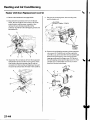
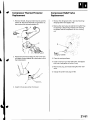
Air Mix ControlMotor Replacement
1 . Removethe under-dashfuse/relaybox (seepage
22-491.
Disconnectthe 5P connector{A) from the air mix
control motor (B).Removethe self-tappingscrews
and the air mix control motor from the heaterunit.
R e m o v et h e r o d ( C )f r o m t h e a r m ( D )o f t h e a i r m i x
controi motor.
,.,:l'
. lf the linkageand door move smoothly,replace
the air mix control motor.
. l f t h e l i n k a g eo r d o o r s t i c k o rb i n d ,r e p a i r t h e ma s
needed.
. lf the air mix control motor runs smoothly,go to
step 3.
AIRMIX CONTROLMOTOR
3 . Installthe motor in the reverseorder of removal.
After installation,make surethe motor runs
smoothly.
3 . Measurethe resistancebetweenthe No. 4 and
No. 5 terminals.lt should be between2.1 k to
3 . 9k Q .
4 . Reconnectthe air mix control motor 5P connector,
t h e nt u r n t h e i g n i t i o ns w i t c hO N { l l ) .
Using the BackprobeSet, measurethe voltage
betweenthe No. 3 and No. 4 terminals.
Max Cool about 1V
Max Hot
about 4 V
lf eitherthe resistanceor voltage readingsare not
as specified,replacethe air mix cotrol motor.
21-34
\'
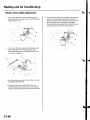
Mode ControlMotor Test
'1.
Disconnectthe 10Pconnectorfrom the mode
control motor.
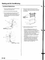
Mode ControlMotor Replacement
1 . R e m o v et h e E C M( s e ep a g e 1 1 - 4 ) .
2. Removethe relay mount bracketbolt, and move
Connectbatterypower to the No. 1 terminal of the
mode control motor, and groundthe No. 2
terminal;the mode control motor should run
smoothly and stop at Defrost.lf it doesn't,reverse
the connections;the mode control motor should
run smoothly and stop at Vent.When the mode
control motor stops running,disconnectbattery
power immediately.
the relaysout of the way.
3 . Disconnectthe 10Pconnector{A) from the mode
control motor (B).Removethe self-tappingscrews
and the mode control motor from the heaterunit.
MODECONTROLMOTOR
3. lfthe mode control motor does not run in step 2,
remove it, then checkthe mode control linkageand
doors for smooth movement.
4 . lnstallthe motor in the reverseorder of removal.
lvlakesure the pin on the linkageis properly
engagedwith the motor. After installation.make
sure the motor runs smoothly.
. lf the linkageand doors move smoothly. replace
the mode control motor.
. l f t h e l i n k a g eo r d o o r s s t i c ko r b i n d ,r e p a i r t h e m
as neeoeo.
. lfthe mode control motor runs smoothly,go to
step 4.
4 . Use a digital multimeterwith an output of 1 mA or
lessat the 20 k Q range.With the mode control
motor running as in step 2, checkfor continuity
b e t w e e nt h e N o . 4 , 5 , 6 , 7 , 8 , a n d 9 t e r m i n a l sa n d
t h e N o . 1 0t e r m i n a li n d i v i d u a l l yT.h e r es h o u l db e
c o n t i n u i t yf o r a m o m e n ta t e a c ht e r m i n a la s t h e
motor moves past each mode position.
lf there is no continuityfor a moment at each
terminal. replacethe mode control motor.
21-35
HeatingandAir Conditioning
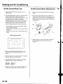
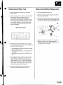
RecirculationControlMotor Test
RecirculationControlMotor
Replacement
I
1. Disconnectthe 5P connectorfrom the recirculation
control motor.
1 . R e m o v et h e E C M( s e ep a g e1 1 - 4 ) .
Incorrectlyapplying power and ground to
the recirculationcontrol motor will damge it.
Follow the instructionscarefullv.
2. Connectbattervoower to the No. 5 terminal ofthe
recirculationcontrol motor, and ground the No. 1
and No. 2 terminals;the recirculationcontrol motor
should run smoothly.To avoid damagingthe
recirculationcontrol motor, do not reversepower
and ground. Disconnectthe No. 1 or No. 2
terminalsfrom ground;the recirculationcontrol
motor should stop at Freshor Recirculate.Don't
cyclethe recirculationcontrol motor {or a long time.
Removethe relay mount bracketbolt.and move
the relaysout of the way,
Disconnectthe 5P connector(A)from the
recirculationcontrol motor (B),Removethe selftapping screwsand the recirculationcontrol motor
from the blower unit.
RECIRCULATION
CONTROL
MOTOR
Installthe motor in the reverseorder of removal.
Make sure the pin on the motor is properly
engagedwith the linkage.After installation.make
sure the motor runs smoothly.
lf the recirculationcontrol motor does not run in
step 2, remove it, then checkthe recirculation
control linkageand doors for smooth movement.
. lfthe linkageand doors move smoothly,replace
the recirculationcontrol motor.
. l f t h e l i n k a g e o r d o o r s s t i c k obr i n d ,r e p a i r t h e m
as neeoeo.
21-36
\
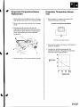
EvaporatorTemperatureSensor
Replacement
1 . Removethe driver'sdashboardlower cover (see
page 20-59)and the under cover (seepage 20-60).
Removethe under-dashfuse/relaybox (seepage
22-491.
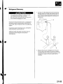
EvaporatorTemperatureSensor
Test
l. Dip the sensorin ice water, and measurethe
resistancebetweenits terminals
EVAPORATOR
TEMPERATURE
SENSOR
Disconnectthe 2P connector(A)from the
evaporatortemperaturesensor(B),then remove
the connectorclip (C).Removethe self-tapping
screw,and carefullypull out the evaporator
temperature.
Terminalside ol male terminals
2 . Then pour hot water on the sensor,and check{or a
changein resistance.
3 . Comparethe resistancereadingswith the
specificationsshown in the graph;the resistance
should be within the specifications
4. Installthe sensorin the reverseorder of removal,
RESISTANCE
k9
t0
32
0
50
10
68
20
86 'F
30'c
TEMPERATURE
21-37
HeatingandAir Gonditioning
PowerTransistorTest
1. Disconnectthe 4P connectorfrom the power
Iranslslor.
2, Measurethe resistancebetweenthe No. 1 and
No. 2 terminalsof the power transistor.lt should be
'1.4
1 . 5k Q .
about
. lf the resistanceiswithln the specifications,
go to
step 3.
. lf the resistanceis notwithin the specifications,
replacethe power transistor.
a
HeaterControlPaneland Push
Switch AssemblyRemovaland
Installation
1 . Removethe centerpanel (seepage 20-62).
Removethe dials (A),then removethe self-tapping
screwsand the heatercontrol panel (B)from the
centerpanel (Cl. Removethe self-tappingscrews
and the push switch assembly(D)from the center
panel.
POWERTRANSISTOB
C a r e f u l l yr e l e a s et h e l o c kt a b o n t h e N o . 4 t e r m i n a l
(BLUI/EL)(A) in the 4P connector,then removethe
terminaa
l n d i n s u l a t ei t f r o m b o d y g r o u n d .
\
3 . lnstallthe control panel and push switch assembly
in the reverseorder of removal.After installation,
operatethe control panel controlsto see whether it
worKspropeny.
functionto confirm that
4 . Runthe self-diagnosis
there are no problemsin the system (seepage218).
(To112
power
o w e rssource
2V p
o u r c eo
on
n vvehicle)
ehicle)
Reconnectthe 4P connectorto the power transistor.
S u p p l y1 2v o l t st o t h e N o . 4 c a v i t yw i t h a j u m p e r
wire.
T u r nt h e i g n i t i o ns w i t c hO N ( l l ) ,a n d c h e c kt h a tt h e
b l o w e rm o t o r r u n s .
. lf the blower motor does not run, replacethe
power rranstsror.
. l f t h e b l o w e rm o t o r r u n s , t h ep o w e r t r a n s i s t o r i s
oK.
21-38
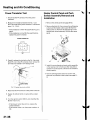
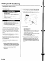
Dustand PollenFilterReplacement
The dust and pollenfilters should be replacedevery
3 0 , 0 0 0m i l e s( 4 8 . 0 0 0
k m ) o r 2 4 m o n t h sw h i c h e v e r
comes first. Replacethe filters more often if the air flow
i s l e s st h a n u s u a l .
1. Openthe glove box. Removeboth glove box stops,
then let the glove box hang down (seepage 20 63).
2 . R e m o v et h e f i l t e rl i d ( A ) f r o mt h e b l o w e ru n i t ,t h e n
p u l l o u t t h e f i r s td u s ta n d p o l l e nf i l t e r( B ) .S l i d et h e
secondfilter to the left,and pull it out.
BlowerUnit Removaland
lnstallation
For some models:SRScomponentsare locatedin this
area.Reviewthe SRScomponentlocations(seepage
23-13)and precautionsand procedures(seepage 23-14)
in the SRSsectionbeforeperforming repairsor service.
1. Make sure you havethe anti-theftcode for the radio,
then write down the frequenciesfor the preset
buttons.
2. Disconnectthe batterynegativecable,and wait 3
minutesbefore beginningworK.
3. Removethe right kick panel (see page 20-50),
passenger'sdashboardlower cover,and the glove
box {seepage 20-63).
4. Cut the plasticcross bracein the glove box opening
with diagonalcuttersin the area shown. Remove
and discardthe plasticcross brace,
Removethe filter {A) from the housing (B),and
replacethe filter.
Cut heare.
4. Installthe filters in the reverseorder of removal.
{cont'd)
21-39
Heatingand Air Gonditioning
Blower Unit Removaland Installation{cont'd}
Removethe steeringhangerbeam bracketcover
from the right side of the glove box opening,then
removethe bolts and the olove box frame.
10. Disconnecttheconnector{A) from the recirculation
control motor, then removethe wire harnessclip
{B).Removethe mounting bolts,the mounting nuts
a n d t h e b l o w e ru n i t ( C ) .
Removethe ECM(seepage 11-4).
1 . Removethe EPScontrol unit (seepage 17-67).
6 x 1 . 0m m
I
9.8N.m(1.0kgt.m,
7.2tbt.ftl
8 . Disconnectand removethe PGM-Flmain relays
and bracketassembly,then removethe ECM
bracket.
9 . Disconnectthe connectors{A) from the blower
motor and the power transistor,then removethe
wire harnessclips (B)and the connectors(C).
Removethe self-tappingscrewsand the bracket(D).
A
6x1.0mm
9.8 N.m (1.0kgf.m,
?.2 tbf.ft)
1 1 .I n s t a l l l h eu n i t i n t h e r e v e r s eo r d e ro f r e m o v a l .
M a k es u r et h a tt h e r ei s n o a i r l e a k a g e .
Reconnectthe negativebatteryterminal.
'13.
D o t h e e n g i n ec o n t r o lm o d u l e( E C M )i d l e l e a r n
procedure
{ s e ep a g e1 1 - 1 3 9 ) .
1 4 . Enterthe anti-theftcode for the radio,then enter
the customer'sradio station presets.
21-40
\
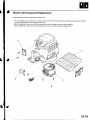
Blower Unit ComponentsReplacement
Nole these items when overhaulingthe blower unit;
' The recirculationcontrol motor (A),the power transistor(B),the blower motor (C),and the dust and pollenfiltefs (D)
can be replacedwithout removingthe blower unit.
. Beforereassembly,make surethatthe recirculationcontrol linkageand doors move smoothly.
. After reassembly,make surethe recirculationcontrol motorruns smoothly (seepage 2j-36).
A
21-41
Heatingand Air Gonditioning
a
EvaporatorCoreReplacement
1 . Recoverthe refrigerantwith a recovery/recycling/
chargingstation(seepage 21-53).
5. Carefullypull out the evaporatorcore without
bendingthe pipes.
Removethe bolt, then disconnectthe suctionline
(A) and the receiverline (B)from the evaporator
core.
6x10mm
9.8N.m(1.0kgt.m,7.2lbf.ft)
Removethe blower unit (seepage 21-39).
Removethe self-tappingscrewsand the expansion
valve cover.
21-42
6 . Installthecore in the reverseorder of removal,and
note these items.
. lfyou're installinga new evaporatorcore, add
r e f r i g e r a not i l ( K E l H l NS P - ] 0 )( s e ep a g e2 1 - 6 ) .
. Replacethe O-ringswith new ones at eachfitting,
and apply a thin coat of refrigerantoil before
installingthem. Be sure to use the correctO-rings
f o r H F C - 1 3 4(aR - ' 1 3 4 tao) a v o i dl e a k a g e .
. l m m e d i a t e l y a f t eurs i n g t h eo i l , r e i n s t a l l t h e c a p
on the container,and seal it to avoid moisture
absorotion.
. Do not spill the refrigerantoil on the vehicle;it
may damagethe paint. lf the refrigerantoil
contactsthe paint,wash it off immediately.
. Chargethe system (seepage 21-55).
HeaterUnit/CoreReplacement
SRScomponentsare locatedin this area.Reviewthe
SRScomponentlocations(seepage23'13),and
precautionsand procedures(seepage 23-14)in the SRS
sectionbefore performingrepairsor service.
1. Make sure you have the anti-theftcode forthe radio,
then write down the freouenciesfor the radio's
Dresetbuttons.
6. Slidethe hose clamps (A) back,then d isconnectthe
inlet heaterhose (B)and the outlet heaterhose (C)
from the heatercore. Enginecoolantwill run out
when the hosesare disconnected;drain it into a
clean drip pan. Be sure not to let coolantspill on
the electricalpartsor the paintedsurfaces.lf any
coolantspills,rinse it off immediately.
Disconnectthe negativecablefrom the battery,
Disconnectthe suctionand receiverlinesfrom the
evaporator core (see page 21-42).
4 . From underthe hood, open the cableclamp (A),
then disconnectthe heatervalve cable (B)from the
heatervalve arm (C).Turn the heatervalve arm to
the fully openedpositionas shown
7 . Removethe bolt and the heatervalve,then remove
the mounting nut from the heaterunit. Takecare
not to damageor bend the fuel lines and the brake
lines,etc.
W h e nt h e e n g i n ei s c o o l ,d r a i nt h e e n g i n ec o o l a n t
from the radiator(seepage 10-6).
8 x 1.25mm
12 N.m (1.2kgf.m,8.7lbf.ft)
(cont'd)
21-43
Heatingand Air Conditioning
HeaterUnit/CoreReplacement(cont'd)
8. Removethe dashboard{seepage 20-66).
1 1 . R e m o v et h e m o u n t i n gb o l t s ,t h e m o u n t i n gn u t s ,
and the heaterunit.
9. Disconnecttheconnectors(A) from the blower
motor, the recirculationcontrol motor, the mode
control motor, and the power transistor,then
removethe wire harnessclips (B)and the
connector(C).Removethe self-tappingscrewsand
the bracket(D).
7 t ,
5 x 1 . 0m m
9.8 N.m
11.0kgl m,
7.2 tbf.ftl
12. Removethe self-tappingscrewsand the expansion
1 0 ,Disconnectthe connectors(A) from the evaporator
temperaturesensorand the air mix control motor,
then removethe wire harnessclips (B) and the
connector(C).Removethe self-tappingscrew and
the cover (D).Disconnectthe heatervalve cable (E).
valve cover (A).Carefullypull out the evaporator
core (B)so you don't bendthe inlet and outlet pipes.
Removethe grommet (C),then removethe selftapping screwsand the flange cover (D).Bemove
the self-tappingscrewsand the pipe cover (E),then
carefullypull out the heatercore (F)so you don't
bend the inlet and outlet oioes.
@
21-44
13. Installthe heatercore and the evaporatorcore in
the reverseorder of removal.
14. Installthe heaterunit in the reverseorder of
removal,and note these items:
. Do not interchangethe inlet and outlet heater
hoses,and installthe hoseclamps securely.
. Refillthecooling systemwith engine coolant(see
page 10-6).
. Adjust the heatervalve cable (see page2'l-461.
. Make sure that there is no coolantleakage.
. Make sure that there is no air leakage.
. Referto evaporatorcore replacement{seestep 6
o n p a g e2 1 - 4 2 ) .
. Do the enginecontrol module (ECl\4)idle learn
p r o c e d u r e( s e ep a g e1 1 - 1 3 9 ) .
. Enterthe anti-theftcode for the radio,then enter
the customer'sradio stationDresets.
21-45
Heatingand Air Conditioning
HeaterValveCableAdjustment
1 . F r o mu n d e r t h eh o o d ,o p e nt h e c a b l ec l a m p{ A ) ,
then disconnectthe heatervalve cable (B)from the
heatervalve arm {C).
5, From under the hood,turn the heatervalve arm {C)
to the fully closedpositionas shown, and hold it.
Attachthe heatervalve cable (B)to the heatervalve
a r m ,a n d g e n t l yp u l l o n t h e h e a t e rv a l v ec a b l e
housingto take up any slack,then installthe heater
v a l v ec a b l eh o u s i n gi n t ot h e c a b l ec l a m p( A ) .
.'.-:',,
- " l l
......
t
From under the dash,disconnectthe heatervalve
c a b l eh o u s i n gf r o m t h e c a b l ec l a m p( A ) ,a n d
disconnectthe heatervalve cable (B)from the air
m i x c o n t r o l i n k a g e{ C ) .
\
t.- l
,
\'r2t'
'
''' '
::"'
Set the temperaturecontrol dial on Max Cool with
the ignition switch ON (ll).
Attachthe heatervalve cable (B)to the air mix
control linkage(C)as shown above,then snap the
h e a t e rv a l v ec a b l eh o u s i n gi n t ot h e c a b l ec l a m p( A ) .
21-46
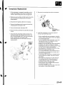
CompressorReplacement
1 . l f t h e c o m p r e s s oirs m a r g i n a l l yo p e r a b l er,u n t h e
engineat idle speed,and let the air conditioning
work for a few minutes,then shut the engine off.
8. Removethe mounting bolts and the compressor.
2. Make sure you have the anti-theftcode for the radio,
then write down the frequenciesfor the radio's
presetbuttons.
3. Disconnectthe negativecablefrom the battery.
4. Recoverthe refrigerantwith a recovery/recycling/
chargingstation(seepage 21-53).
5. Removethe alternator(seepage 4-29).
6. Removethe Ay'Ccondenserfan assembly(seepage
10-10).
7. Disconnectthecompressorclutchconnector(A),
removethe bolts,then disconnectthe suction line
( B )a n d t h e d i s c h a r g el i n e( C ) f r o mt h e c o m p r e s s o r .
Plug or cap the lines immediatelyafter
disconnectingthem to avoid moistureand dust
contamination.
6 x '1.0mm
9.8 N.m
11.0kgt.m,
7.2 tbl.ttl
u1/
(
o
8 x 1 . 2 5m m
22 N.m12.2kgf.m.
9 . I n s t a l l t h ec o m p r e s s oirn t h e r e v e r s eo r d e ro f
removal,and note these items:
. Beforeinstallingthe new compressor,checkfor
m e t a lo r o t h e rc o n t a m i n a t i o inn t h e l i n e .R e p l a c e
any contaminatedparts.
. lf you're installinga newcompressor,you must
calculatethe amount of refrigerantoil to be
removedfrom it (seepage 21-6).
. Replacethe O-ringswith new ones at each fitting,
and apply a thin coat of refrigerantoil before
installingthem. Be sure to use the correctO-rings
f o r H F C - 1 3 4{aR - 1 3 4 at o
) a v o i dl e a k a g e ,
. U s er e f r i g e r a not i l ( K E l H l NS P - ' 1 0f o
) r HFC-134a
K E I H I Ns p i r a lt y p e c o m p r e s s oor n l y .
. To avoid contaminatlon,do not returnthe oilto
the containeronce dispensed,and never mix it
with other refrigerantoils.
. l m m e d i a t e l ya f t e ru s i n gt h e o i l , r e i n s t a l l t h ec a p
on the container,and seal it to avoid moisture
absorption.
. Do not spill the refrigerantoil on the vehicle;it
may damagethe paint. lf the refrlgerantoil
contactsthe paint,wash it off immediately.
. Chargethe system (seepage 21-55).
. D o t h e e n g i n ec o n t r o lm o d u l e( E C M )i d l e l e a r n
p r o c e d u r e( s e ep a g e1 1 - ' 1 3 9 ) .
. Enterthe antitheft code for the radio,then enter
the customer'sradio station presets.
21-47
HeatingandAir Gonditioning
a
CompressorClutchCheck
1 . Checkthe armatureplatefor discoloration,peeling,
or other damage.lf there is damage,replacethe
clutch set (seepage 21-49),
Checkthe rotor pulley bearingplay and drag by
rotatingthe rotor pulley by hand.Beplacethe
clutchset with a new one if it is noisy or has
excessiveplay/drag(seepage 21-49).
4. Releasethe field coil connectorf rom the holder,
then disconnectit. Checkthe thermal protectorfor
continuity.lf there is no continuity,replacethe
t h e r m a lp r o t e c t o (r s e ep a g e2 1 - 5 1 ) .
NOTE:The thermal Drotectorwill have no
. hen
c o n t i n u i t ya b o v e2 5 2 t o 2 7 0 " F\ 1 2 2 l o 1 3 2 ' C )W
t h et e m p e r a t u r e
d r o p sb e l o w2 4 1t o 2 1 9 ' F( 1 1 6t o
104'C),the thermal protectorwill have continuity.
,\.
Measurethe clearancebetweenthe rotor pulley (A)
and the armatureplate (B)all the way around.lf the
clearanceis not within specifiedlimits, removethe
armatureplate (seepage 21-49)and add or remove
shims as neededto increaseor decreaseclearance.
Checkresistanceof the field coil. lf resistanceis not
within specifications,replacethe field coil
( s e ep a g e2 1 - 4 9 ) .
FieldCoil Resistance: 3.05 3.35ohmsat68"F
Clearance: 0.510.15 mm {0.02010.006in.)
N O T ET
: h e s h i m sa r e a v a i l a b l ei n f o u r t h i c k n e s s e s :
0 . 1m m . 0 . 2m m , 0 . 4m m , a n d0 . 5m m .
21-48
t20"c)
Compressor
ClutchOverhaul
Special Tool Required
A,/Cclutch holder,Robinair10204.Kent-MooreJ37872,
or HondaTool and EquipmentKMT-J33939,
c o m m e r c i a l la
yvailable
1 . R e m o v et h e c e n t e rn u t ( A )w h i l e h o l d i n gt h e
armatureplatewith a commerciallyavailableA,/C
c l u t c hh o l d e r( B ) .
1 7 . 6N . m
{1.8kgf.m,
13 tbt.ft)
3. lf you are replacingthe field coil, removethe snap
ring (A) with snap ring pliers,then removethe rotor
pulley (B).Be careful not to damagethe rotor pulley
or tne compressor.
\ot
-@
/@h"
.ffi
Removethe armatureplate (A) and shim(s)(B),
taking care not to losethe shim(s).lf the clutch
needsadjustment,increaseor decreasethe
number and thicknessof shims as necessary,then
reinstallthearmatureDlate,and recheckits
clearance(see page21-481.
4. Removethe bolt and holder (A).then disconnect
the field coil connector(B).Loosenthe clamp screw
(C)to iree the field coil wire. Removethe snap ring
{ D ) w i t hs n a pr i n g p l i e r s t, h e n r e m o v et h e f i e l dc o i l
(E).Be careful not to damagethe field coil or the
comoressor.
N O T ET
: h e s h i m sa r e a v a i l a b l ei n f o u r t h i c k n e s s e s :
0 . 1 m m , 0 . 2 m m , 0 . 4 m m , a n d 0 . 5m m .
9-=-g
7.4 N.m
(0.75kgf m,
5 tbf.ft)
----------------
"\)
(cont'd)
21-49
HeatingandAir Gonditioning
CompressorClutchOverhaul(cont'd)
5. Reassemblethe clutch in the reverseorder of
disassembly,and note these items:
. I n s t a l l t h ef i e l dc o i lw i t h t h e w i r e s i d ef a c i n g
down, and align the boss on the field coil with the
h o l ei n t h e c o m p r e s s o r .
. Cleanthe rotor pulley and compressorsliding
surfaceswith contactcleaneror other
non-petroleumsolvent.
. I n s t a l l n e w s n a pr i n g s ,n o t et h e i n s t a l l a t i o n
direction,and make surethey are fully seatedin
the groove.
. Make sure that the rotor pulleyturns smoothly
after it's reassembled,
. R o u t ea n d c l a m pt h e w i r e sp r o p e r l yo r t h e y c a n
be damagedby the rotor pulley.
21-50
CompressorThermalProtector
Replacement
1. Removethe bolt,the ground terminal (A),and the
holder (B).Disconnectthe field coil connector(C).
then removethe thermal protector(D).
CompressorReliefValve
Replacement
1 . Recoverthe refrigerantwith a recovery/recycling/
chargingstation(seepage 21-53).
2 . Removethe reliefvalve (A) and the O-ring (B).Plug
the openingto keepforeign mafterfrom entering
the system and the compressoroil from running
out.
7.4 N.m
(0.75kgf.m,
5 rbf.ftl
A
9,8 N.m
(1.0kgf m,7.2lbf.ft)
Replacethe thermal protector(A)with a new one,
and apply siliconesealant(B)to the bottom of the
thermal Drotector.
Clean the mating surfaces.
4 . Installa new O-ringon the reliefvalve, and apply a
thin coat of refrigerantoil to the O-ring.
Removethe plug, and installand tightenthe relief
valve.
Chargethe system (seepage21-55).
A
3. lnstall in the reverse order of removal.
21-51
Heatingand Air Conditioning
GondenserReplacement
1 . Recoverthe refrigerantwith a recovery/recycling/
chargingstation(seepage 21-53).
Removethe front bumper {seepage 20-85).
Removethe bolts,then disconnectthe discharge
line (A) and the condenserline (B)from the
condenser.Plug or cap the lines immediatelyafter
disconnectingthem to avoid moistureand dust
conlamtnaflon.
4, Removethe mounting bolts,then removethe
condenserby lifting it up. Be carefulnot to damage
the radiatoo
r r t h e c o n d e n s efri n s w h e n r e m o v i n o
the condenser.
6 x '1.0mm
9.8 N.m ('1.0kgf.m,
7.2 tbl.ftl
t
t-
-"'.
f,
-li
:.--\ ----
.:)-
- -'
5 . l n s t a l l t h ec o n d e n s eirn t h e r e v e r s eo r d e ro f
removal,and note these items.
6x1.0mm
9.8 N.m ('1.0kgf.m,7.2lbf.ft)
,t\
6x1.0mm
9.8 N.m (1.0kgt.m.7.2lbf.ft)
21-52
. l f y o u ' r ei n s t a l l i n ga n e w c o n d e n s e ra,d d
r e f r i g e r a not i l ( K E l H l NS P -1 0 )l s e ep a g e2 1 ' 6 ) .
. Replacethe O-ringswith new ones at eachfitting,
and apply a thin coat of refrigerantoil before
installingthem. Be sure to usethe correctO-rings
t ov o i dl e a k a g e .
f o r H F C - 1 3 4(aR - ' 1 3 4 a ) a
. lmmediatelyafter using the oil, reinstallthecap
on the container,and seal it to avoid moisture
absorption.
. D o n o t s p i l l t h er e f r i g e r a not i l o n t h e v e h i c l e ; i t
may damagethe paint.lf the refrigerantoil
contactsthe paint,wash it off immediately.
. Be carefulnot to damagethe radiatoror the
condenserfins when installingthe condenser.
. Chargethe system (seepage 21-55).
RefrigerantRecovery
Air conditioningrefrigerantor lubricantvapor
can irritateyour eyes,nose.or throat.
Be carefulwhen connectingserviceequipment.
Do not breatherefrigerantor vapor
1. Connecta R-134arefrigerantrecovery/recycling/
chargingstation{A) to the high-pressureservice
port (B)and the low-pressureserviceport (C),as
shown, following the equipmentmanufacturer's
instructions.
1!l
Use only serviceequipmentthat is U.L.-listedand is
certifiedto meet the requirementsof SAE J2210to
r e m o v eH F C - 1 3 4(aR - 1 3 4 af r) o m t h e a i r c o n d i t i o n i n g
system.
lf accidentalsystemdischargeoccurs,ventilatethe
work area before resumingservice
-'',
r:
i
-
'=i
-:
t:
(
-
r
Additionalhealthand safetyinformationmay be
obtainedfrom the refrigerantand lubricant
manufacturers.
lvleasurethe amount of refrigerantoil removed
from the Ay'Csystem after the recoveryprocessis
completed.Be sure to put the same amount of new
refrigerantoil backinto the Ay'Csystem before
chargrng.
21-53
Heatingand Air Conditioning
SystemEvacuation
. Air conditioningrefrigerantor lubricantvapor
can irritateyour eyes,nose,or throat.
. Be carefulwhen connectingserviceequipment.
. Do not breatherefrigerantor vapor.
Use only serviceequipmentthat is U.L.-listedand is
certifiedto meet the requirementsof SAE J2210to
r e m o v eH F C - 1 3 4(aR - 1 3 4 a ) f r o m
t h e a i rc o n d i t i o n i n q
system.
2. Connecta R-134arefrigerantrecovery/recycling/
chargingstation(A)to the high-pressureservice
pon (B)and the low-pressureserviceport (C),as
shown,following the equipmentmanufacturer's
instructions.Evacuatethe system.
-i -
r4.t
lf accidentalsystem dischargeoccurs,ventilatethe
work area before resumingservice.
Additionalhealthand safety informationmay be
obtainedfrom the refrigerantand lubricant
manufacturers.
1. When an Ay'Csystem has been openedto the
atmosphere,such as during installationor repair,it
must be evacuatedusing a R-134arefrigerant
recovery/recycling/charging
station(lf the system
has been open for severaldays,the receiver/dryer
should be replaced,and the system should be
evacuatedfor severalhours.)
lf the low-pressuredoes not reachmore than 93.3
k P a{ 7 0 0m m H g ,2 7 . 6i n . H g )i n 1 5 m i n u t e st,h e r ei s
probablya leak in the system.Partiallychargethe
system,and checkfor leaks(seestep 3 on page 2156).
21-54
SystemCharging
2 . Evacuatethe system(seepage 21'54).
Air conditioningrefrigerantor lubricantvapor
can irritateyour eyes,nose,or throat.
Be carefulwhen connectingserviceequipment.
Do not breatherefrigerantor vapor,
3 . Add the same amount of new refrigerantoil to the
systemthat was removedduring recovery.Use
only KEIHINSP-10refrigerantoil.
4 . Chargethe system with the specifiedamount of
dn di s
U s eo n l y s e r v i c ee q u i p m e ntth a t i s U . L . ' l i s t e a
certifiedto meet the requirementsof SAEJ2210to
r e m o v eH F C - 1 3 4{aR - 1 3 4 af r) o m t h e a i r c o n d i t i o n i n g
system.
lf accidentalsystem dischargeoccurs,ventilatethe
work area before resumingservice
Additionalhealthand safetyinformationmay be
obtainedfrom the refrigerantand lubricant
manufacturers.
R-134arefrigerant.Do not overchargethe system;
the compressorwill be damaged.
Selectthe appropriateunits of measurefor your
refrigerantchargingstation.
Refrigerant capacity:
500 to 550 g
0.50to 0.55 kg
1 . 1 0t o 1 . 2 1l b s
17.6to 19.4oz
Checkfor refrigerantleaks(seepage 21'56).
1. Connecta R-134arefrigerantrecovery/recycling/
c h a r g i n gs t a t i o n( A )t o t h e h i g h - p r e s s u rsee r v i c e
pon (B)and the low-pressureserviceport {C),as
shown, following the equipmentmanufacturer's
instructions.
Checkfor system performance(seepage 21-58).
21-55
HeatingandAir Conditioning
RefrigerantLeakTest
Special Tool Required
Leakdetector,HondaTool and EquipmentYGK-H-10PM
c o m m e r c i a l la
vvailable
1. Connecta R-134arefrigerantrecovery/recycling/
chargingstation(A)to the high-pressureservice
port (B)and the low-pressureserviceport (C),as
shown, following the equipmentmanufacturer's
anstructions.
Compressedair mixed with R-134aforms a
combustiblevapor.
The vapor can burn or explodecausingserious
injury.
Neverusecompressed
airto pressure
test
R - 1 3 4 as e r v i c ee q u i p m e n ot r v e h i c l ea i r
conditioningsystem.
A i r c o n d i t i o n i n gr e f r i g e r a not r l u b r i c a nvt a p o r
can irritateyour eyes,nose,or throat.
Be carefulwhen connectingserviceequipment.
Do not breatherefrigerantor vapor
Use only serviceequipmentthat is U.L.-listedand is
certiifiedto meet the requirementsof SAE J2210to
r e m o v eH F C - 1 3 4(aR - 1 3 4 af r) o m t h e a i r c o n d i t i o n i n g
system.
lf accidentalsystem dischargeoccurs,ventilatethe
work area before resumingservice.
R - 1 3 4 as e r v i c ee q u i p m e n o
t r v e h i c l ea i r c o n d i t i o n i n g
systemsshould not be pressuretestedor leaktested
with compressedair.
Additionalhealthand safety informationmay be
obtainedfrom the refrigerantand lubricant
manufacturers.
Open the high pressurevalve to chargethe system
to the specifiedcapacity,then closethe supply
valve,and removethe chargingsystem couplers.
Selectthe appropriateunits of measurefor your
refrigerantchargingstation.
Refrigerant capacity:
500 to 550 g
0.50to 0.55kg
1 . 1 0t o 1 . 2 1l b s
17.6to 19.4oz
3 . Checkthe systemfor leaksusing a R-134a
refrigerantleak detectorwith an accuracyof 14 g
(0.5oz) per year or better.
lf you find leaksthat requirethe systemto be
opened(to repair or replacehoses,fittings,etc.),
recoverthe system.
After checkingand repairingleaks,evacuatethe
system.
21-56
A/C SystemTests
Pressure
Test
Test results
(high)
Discharge
pressure
abnormallyhigh
svmotom3
pressure
Afterstoppingcompressor,
to
dropsquickly,andthencontinues
Beduced
or no airflow through
condenser
hot.
Lineto condenser
is excessively
DGaUSe
Air in system
Cloggedcondenser
or radiator
fins
or radiatorfan not
Condenser
Restrictedflow of refrigerantin
discharge
pressure Highand low pressures
arebalanced . Faultycompressor
Discharge
valve
Low
soonafterstoppingcompressor,
. Faultvcomoressor
seal
sideis hioherthannormal.
valve
Faultyexpansion
Outletof expansionvalve is not
gaugeindicates
Moisturein system
frosted,low pressure
(low)
Suction
pressure
low
abnormally
Suctionpressure
high
abnormally
Expansion
valveis not frosted,and
lineis not cold.Low
low-pressure
pressure
gaugeindicates
vacuum,
is low,andthe Frozenevaporator
Discharge
temperature
air flow from vents is restricted.
Exoansion
valveis frosted.
Receivetdryer
outletis cool,and inlet Cloggedreceiver/dryer
is warm (shouldbe warm during
ooeralton),
Low pressure
hoseandcheckjointare E x p a n s i o nv a l v e o p e n t o o l o n g
around
coolerthanthetemperature
evaoorator,
in system
refrigerant
Excessive
is loweredwhen
Suctionpressure
..nrlenser
is cooled bv water.
areequalized
Highand low pressure
is stopped,
assoonasthecompressor
while
andbothgaugesfluctuate
Suctionand
dascharge
pressures
abnormallv
hioh
Suctionand
pressure
discharge
abnormally
low
leaks
Fefrigerant
' Frozenexpansion
valve
(Moisturein system)
. Faultyexpansion
valve
Faultygasket
valve
Faultyhigh pressure
Foreignpaniclestuckin high
or radiator
Reduced
airflow throughcondenser. . Cloggedcondenser
fins
' Condenser
or radiatorfan not
workinoorooerlv
Cloggedor kinkedlow-pressure
hoseand metalend
Low-pressure
hoseoarts
areasarecoolerthanevaoorator,
valve C l o g g e d h i g h - p r e s s u r el i n e
Temperature
aroundexpansion
is too low comparedwith thataround
:omoressor
clulchis dirtv.
lomoressorbolt(s)aredirtv.
; o m D r e s s o ro a s k e t i s w e t w i t h o i l .
:omoressor
shaftsealleakinq
no aroundbolt(s)
iet
no
Recover,evacuate(seepage21-54),
and rechargewith specifiedamount
{seeoaoe21 55).
Clean
Checkfan voltageand rpm.
Checkfan direction.
restricted
lines.
Replace
the compressor.
Beplace
. Replace
valve.
the expansion
. Recover,evacuatefor at least
30 minutes,and rechargewith
sDecified
amount.
Recover,evacuatefor at least
with
30 minutes,and recharge
amount.
specified
valve.
the expansion
Beplace
Runthe fan with compressoroff, then
checkevaooratottemoeraturesensor.
eanor reolace,
Replacereceaver/dryer.
Bepairor replace.
Recover,evacuate,and rechargewith
qnp.ifie.lamo'rnr
Replace
the compressor.
Clean
Checkvoltageand fan rpm.
Checkfan direction.
Repairor replace.
Repairor replace,
Reolace
the comDressor,
Tiohtenbolt{s)ot reolacecomDressor,
acethe comoressor.
(cont'd)
21-57
Heatingand Air Conditioning
A/C SystemTests(cont'd)
PerformanceTest
' Compressedair mixed with R-134aforms a
combustiblevapor.
. T h e v a p o rc a n b u r n o r e x p l o d ec a u s i n gs e r i o u s
Injury.
. Never use compressedair to pressuretest
R - 1 3 4 as e r v i c ee q u i p m e n ot r v e h i c l ea i r
conditioning
systems.
Open the glove box. Removeboth glove box stops,
then let the glove box hang down (seepage 20-63).
4 . Inserta thermometer(A) in the centervent, and
placeanotherthermometer{B) nearthe blower unit.
Air conditioningrefrigerantor lubricantvapor
can irritateyour eyes,nose,or throar.
Be carefulwhen connectingserviceequipment.
Do not breatherefrigerantor vapor.
The performancetest will help determineif the air
conditionersystem is operatingwithin specifications.
Use only serviceequipmentthat is U.L.-listedand is
cenified to meet the requirementsof SAE J2210to
r e m o v eH F C - 1 3 4(aR - 1 3 4 a l f r o m
t h e a i rc o n d i t i o n i n g
system.
lf accidentalsystem dischargeoccurs,ventilatethe
work area before resumingservice
R - 1 3 4 as e r v i c ee q u i p m e n ot r v e h i c l ea i r c o n d i t i o n i n g
systemsshould not be pressuretestedor leaktested
with compressedair.
Additionalhealthand safety informationmay be
obtainedfrom the refrigerantand lubricant
manufacturers.
1 . Connecta R-134arefrigerantrecover/recycling/
chargingstationto the high-pressureserviceport
and the low-pressureserviceport, following the
equipmentmanufacturer'sinstructions.
D e t e r m i n et h e r e l a t i v eh u m i d i t ya n d a i r
Iemperarure.
21-58
Test conditions:
.
.
.
.
Avoid direct sunlight.
Open the hood.
Open the front doors.
Sel the temperaturecontrol dial on Max Cool,the
mode control dial on Vent,and the recirculation
control switch on Recirculate.
. Turn the A,/Cswitch on and the fan switch on Max.
. R u nt h e e n g i n ea t 7 5 0 r p m .
. N o d r i v e ro r p a s s e n g e risn v e h i c l e .
A f t e r r u n n i n gt h e a i r c o n d i t i o n i n fgo r I 0 m i n u t e s
underthe above test conditjons,read the delivery
temperaturefrom the thermometerin the center
vent, the intaketemperaturenear the blower unit,
and the high and low system pressurefrom the Ay'C
g au g e s .
7. To completethe charts:
.
.
.
.
.
.
.
.
M a r k t h ed e l i v e r y t e m p e r a t u a
r el o n gt h e v e r t i c a l i n e .
Mark the intaketemperature(ambientair temperature)along the bottom line.
Draw a line straightup from the air temperatureto the humidity.
M a r ka p o i n t 1 0% a b o v ea n d 1 0% b e l o w t h eh u m i d i t yl e v e l .
From each point. drawa horizontalline acrossthe deliverytemperature.
The delivervtemperatureshould fall betweenthetwo lines
Completethe low-sidepressuretest and high-sidepressuretest in the same way.
Anv measurementsoutsidethe line may indicatethe needfor further inspection.
kPa
(ksl{cm')
Lpsrl
2500[25) _
360l
{kgflcm')
Lpsil
600
{6t
80 yo
a0 0/"
tssl
2000
(201
1280
HUMIDITY
LEVEL
30 9o
fcl
1500{1s}
,21o)
30%
80%
1000(101
:1401
500 {5)
171l
DELIVERY
PRESSURE
100
{11
h4l
INTAKE
PRESSURE
OELIVERY
TEMPERATURE
68
t20l
I
I
86
77
t30)
t25l
INTAKETEMPEBATURE
I
95
(35)
104
{40)
.F
{'cl
21-59