1
Steering
Steering
. . . . . . . . . .1. .7.- 2
S p e c i aTl o o l s
. .7. .-.3. . . . . . . . .
C o m o o n e nLto c a t i oInn d e x . . . . . . . . . . . . . . . . . . . . . . . . . . . 1
17-4
PlayCheck.....................".
WheelRotational
Steering
17-4
..........
PowerAssistCheck..................
17-5
.................
andGearboxInspection
SteeringLinkage
...........
l e m o v a.l . . . . . . . . . . . . . . . . . . . . . . . . , . . . .1. .7. -. 6
S t e e r i nW
g h e eR
17-7
................
WheelDisassembly/Reassembly
Steering
17-8
...............
WheelInstallation
Steering
17-9
Steering
ColumnRemovalandInstallation...........'...
17-11
..............
ColumnInspection
Steering
17-'12
.......................................'.
Replacement
SteeringLock
. . . . . " . . . . . . . . '1. .7' .- .1 3
R a c kG u i d eA d i u s t m e n t
ElectricalPowerSteering(EPS)
17-15
Steering
(
SpecialTools
Ref.No.
o
Tool Number
07MAA-S100200
Description
LocknulWrench.43 mm
E
-.tt)-
---<,/
L\2 r
6Y
.Vo
I
1 7-2
Oty
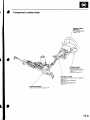
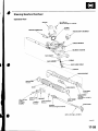
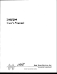
ComponentLocationIndex
DRIVER'S
AIRBAG
ASSEMBLY
Removal/lnstallation,
p a g e2 3 - 1 1 3
STEERINGWHEEL
Removal,page 17-6
Disassembly/Reassembly,
page 17-7
Installation,page 17-8
STEERING
COLUMN
SteeringColumnRemovaland Installation,
p a g e1 7 ' 9
SteeringColumn Inspection,
p a g e1 7 - 1 ' l
SteeringLockReplacement,
page 11-12
STEERING
GEARBOX
page'17-13
RackGuideAdjustment,
17-3
Steering
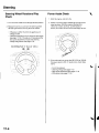
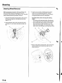
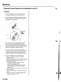
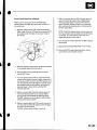
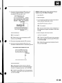
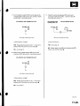
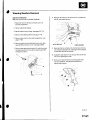
SteeringWheelRotationalPlay
Check
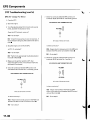
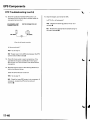
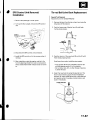
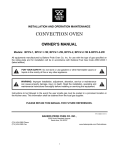
PowerAssistCheck
1 . Startthe engine,and let it idle.
1. Turn the front wheelsto the straightaheadposition.
2. Measurehow far you can turn the steeringwheel
left and right without moving the front wheels.
Attach a commerciallyavailablespring scaleto the
s t e e r i n gw h e e l .W i t h t h e e n g i n ei d l i n ga n d t h e
v e h i c l eo n a c l e a n ,d r y f l o o r ,p u l lt h e s c a l ea s
shown, and read it as soon as the tires begin to turn.
. lf the play is within the limit, the gearboxand
l i n k a g ea r e O K .
. lfthe playexceedsthe
l i m i t ,a d j u s t t h er a c kg u i d e
'17-13).
lf the play is still excessiveafter
{seepage
rackguide adjustment,inspectthe steering
l i n k a g ea n d g e a r b o x{ s e ep a g e1 7 - 5 ) .
BOTATIONAL
PLAY:0 10mm (0-0.39in.l
+ :
3 . l f t h e s c a l er e a d sn o m o r e t h a n2 9 N ( 3 . 0k g f , 6 . 6l b f ) ,
the power assistis OK. lf it readsmore, checkthese
items:
.
.
.
.
17-4
Fronttire pressure
Steeringlinkage(seepage 17-5)
Rackgulde adjustment(seepage 17-13)
EPSsystem (seepage 17-18)
\
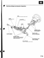
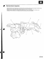
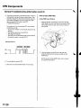
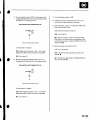
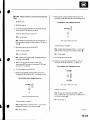
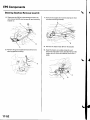
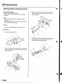
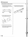
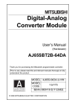
SteeringLinkageand GearboxInspection
BOOT
Inspect
Ior damageanddeterioration.
Checkfor looseness,
a n db i n d i n g .
12 mm BOLTS
Inspectfor looseness.
I
STEERING
COLUMN
Inspect
for loosecolumn
mountinghardware
STEERING
JOINTS
Checkfor looseioint bolts,
andlooseor bindingioints.
TIE.RODLOCKNUTS
Checkfor looseness.
STEERING
GEARBOX
Inspectfor loosemounting hardware.
GEARBOXMOUNTING CUSHIONS
Inspectfor deterioration.
TIE.RODENOBALLJOINT
lnsoect
tor looseness,
b i n d i n ga,n dd a m a g e .
BALLJOINT
BOOT
Inspect
for damageanddeterioration.
17-5
Steering
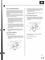
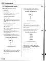
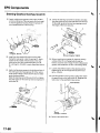
SteeringWheelRemoval
SRScomponentsare locatedin this area.Reviewthe
SRScomponentlocations(seepage 23-13),and
precautionsand procedures(seepage 23-14)in the SRS
sectionbeforeperformingrepairsor service.
1. Align the front wheels straightahead,then remove
the driver'sairbagfrom the steeringwheel (see
p a g e2 3 - 1 1 3 ) .
2. Disconnectthe cruisecontrol sevresumeswitch
connector(A),and loosenthe steeringwheel nut
{B).
{
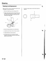
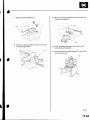
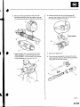
3. Installa commerciallyavailablesteeringwheel
puller {A) on the steeringwheel (B).Freethe
steeringwheel from the steeringcolumn shaft by
t u r n i n gt h e p r e s s u r eb o l t( C )o f t h e p u l l e r .
Note these items when removing the steering
wheel:
. Do not tap on the steeringwheel orthesteering
column shaft when removingthe steeringwheel.
. l f y o u t h r e a dt h e p u l l e rb o l t s( D )i n t o t h e w h e e l
hub more than 5 threads,the bolts will hit the
cable reel and damageit. To preventthis, install
a p a i ro f j a m n u t s5 t h r e a d su p o n e a c hp u l l e rb o l t .
D
i
Bemovethe steeringwheel puller,then removethe
steeringwheel nut and steeringwheel from the
sleerinocolumn.
17-6
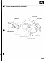
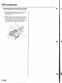
SteeringWheelDisassembly/Reassembly
WHEEL
STEERING
ACCESSPANELA
CONTACTPLATE
75*-=offi
CONNECTORHOLDERS
ffi)Y
MOOULESETBRACKET
-f
STEERING
WHEELREABCOVER
b
/
,/*
accEss
PANEL
B
CRUISECONTROLSWITCH
17-7
Steering
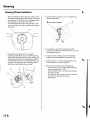
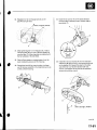
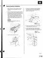
SteeringWheelInstallation
1 . B e f o r ei n s t a l l i n g
t h e s t e e r i n gw h e e l ,m a k es u r et h e
front wheels are alignedstraightahead,then center
the cable reel (A).Do this by first rotatingthe cable
reel clockwiseuntil it stops.Then rotate it
counterclockwiseabout two and a half turns.The
a r r o w m a r k( B )o n t h e c a b l er e e ll a b e ls h o u l dp o i n t
straightup.
3. Installthe steeringwheel nut (A),and tighten it to
the specifiedtorgue.
A
39 N.m(4.0kgf m.29lbt ftl
_
B
lr,',,t
;. _,:!
'' '1i::..'.'l
Connectthe cruisecontrol set/resumeswitch
connector(B).fvlakesure the wire harnessis routed
and fastenedproperly.
Positionthe two tabs (A) of the turn signal
canceling
s l e e v e( B )a s s h o w n .I n s t a l l t h es t e e r i n g
wheel onto the steeringcolumn shaft, makingsure
the steerlngwheel hub (C)engagesthe pins (D) of
the cable reel and tabs of the cancelingsleeve.Do
not tap on the steeringwheel or steeringcolumn
shaft when installingthe steeringwheel.
I n s t a ltlh e d r i v e r ' sa i r b a g a
, n d c o n f i r mt h a tt h e
system is operatingproperly{seepage 23-113).
C h e c kt h e h o r n ,t u r n s i g n a lc a n c e l i n g
a n dc r u i s e
control switchesfor proper operation.
7 . Reconnectthe batteryand do the following:
. D o t h e e n g i n ec o n t r o lm o d u l e( E C M )i d l e l e a r n
p r o c e d u r e( s e ep a g e1 l - 1 3 9 ) ,
. Powerwindow control unit resettingprocedure
\see page 22-1281.
. Enterthe anti-theftcord for the radio,then enter
the custmer'sradio stationpresets.
. Set the clock.
17-8
{
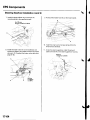
SteeringColumnRemovaland Installation
SRScomponentsare locatedin this area.Reviewthe SRScomponentlocations(seepage 23-13)and precautionsand
procedures(seepage 23-14)in the SRSsectionbefore performingrepairsor service.
Removal
1, Recordthe radio stationpresets,and disconnectthe battery.
2 . R e m o v e t h e d r i v e r ' s a i r b a g a s s e m b l y ( s e e p a g e 2 3 -a1n1d3t)h e s t e e r i n gw h e e l( s e ep a g e1 7 - 6 ) .
p a g e2 0 - 6 0 ) .
3 . R e m o v e t h ed r i v e r ' sd a s h b o a r dl o w e r c o v e r ( s e ep a g e2 0 - 5 9 a) n d u n d e r c o v e r ( s e e
4. Removethe column covers(A:
T
I x 1.25mm
16 N.m (1.6kgf.m,
12 lbl.fr)
b
5 . Disconnectthe wire harnessconnectorsfrom the combinationswitch assembly{B).
6 . Removethe combinationswitch assemblyfrom the steeringcolumn shaft by removingthe screw (C)on the top of
the combinationswitch.
7. Disconnectthe connectorsfrom the ignition switch,and releasethe wire harnessclips from the steeringcolumn.
8. Disconnectthe steeringjoint (D),and remove it from the column shaft.
9. Removethe steeringcolumn {E)by removingthe attachingnuts and bolts.
\
(cont'd)
17-9
Steering
SteeringColumnRemovaland Installation(cont'd)
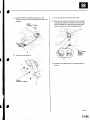
lnstallation
1 . I n s t a ltl h e s t e e r i n gc o l u m n ,a n d m a k es u r et h e
wires are not caught or pinchedby any parts.
Insertthe upper end ofthe steeringjoint onto the
steeringshaft {A) (line up the bolt hole (B)with the
flat portion (C)on the shaft).
8 x 1 , 2 5m m
28 N.m
{2.9 kgf m,
21rbr.ft)
A
Slip the lower end of the steeringjoint onto the
pinion shaft {D) (line up the bolt hole with the
g r o o v e( E )a r o u n dt h e s h a f t )a, n d l o o s e l yl n s t a l l t h e
lower joint bolt. Be sure that the lower joint bolt is
securelyin the groove in the pinion shaft.
4 . Pull on the steeringjoint to make sure that the
s t e e r i n gj o i n t i s f u l l y s e a t e dT. h e n i n s t a l l t h eu p p e r
joint bolt, and tighten it to the specifiedtorque.
Tightenthe lower joint bolt to the specifiedtorque.
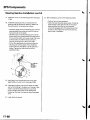
Finishthe installation,and note these items:
. Make surethe wire harnessis routed and
fastenedproperly.
. Make sure the connectorsare properlyconnected.
. R e i n s t a l l t h se t e e r i n gw h e e l( s e ep a g e1 7 - 8 ) .
. Reconnectthe battery.
- Do the power window control unitreset
procedure{seepage 22-128).
- Enterthe anti-theftcode for the radio,then
enterthe custmer'sradio stationpresets.
- Set the clock.
. Verify horn, turn signalswitch,and cruisecontrol
switch operation.
. Checkwheel alignment,if necessary(seepage
18-4).
. D o t h e e n g i n ec o n t r o lm o d u l e( E C M )i d l el e a r n
p r o c e d ur e { s e ep a g e' 1 1 - 1 3 9 ) .
17-10
{
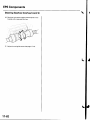
SteeringColumnInspection
. C h e c kt h e s t e e r i n gc o l u m nb a l l b e a r i n g ( A a
) n d t h e s t e e r i n g j o i n t b e a r i n g s ( B ) f o r p l a y a n d p r o p e r m o v e m el fnatn. y
bearingis noisy or has excessiveplay, replacethe steeringcolumn as an assembly,
' C h e c k t h e a b s o r b i n g p l a t e s ( C ) , a b s o r b i n g p l a t e g u i d e s ( D ) , s t o p ( E ) , a n d c o a t i n g p l af o
t er sd(i F
s t)o r t i o na n d
breakage.lf there is distortionor breakage,replacethe steeringcolumn as an assembly.
17-11
Steering
SteeringLockReplacement
NOTE:Do not try to re-keya replacementsteeringlock.
lf necessary,re-keythe other locks.
1 . R e m o v et h e s t e e r i n gc o l u m n( s e ep a g e1 7 - 9 ) .
2. Centerpunch each ofthe two shear bolts (A),and
drill their headsoff with a 5 mm (3i16 in.) drill bit.
Be carefulnot to damagethe switch body when
removingthe shear bolts,
7. Tightenthe shearbolts (A) untilthe hex heads(B)
twist off.
A
I
:..'-":'
3. Removethe shear bolts from the switch body.
4. Installtheswitch body without the key inserted.
5. Looselytighten the new shear bolts.
6. Insertthe ignition key,and checkfor proper
operationof the steeringwheel lock and that the
ignition key turns freely.
17-12
I
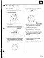
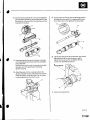
RackGuideAdjustment
Special Tool Required
Locknutwrench, 43 mm 07MAA-S100200
6. Tightenthe rackguidescrew(A)ro25 N.m (2.5
kgf.m,18lbf.ft).thenloosenit.
5" Max.
1. Set the wheels in the straightaheadposition.
j
i-rrrr-,
2. Removethe heat shield(A).
'-.i. ''
'
9 . 8N . m ( r . 0 k g f . m , 7 . 2 l b t f t )
I
32 on page 13-8).
4il N.m
{a.5kgf.m,33lbt.ft)
3 . Removethe transmissionmount bracket(seestep
7 . Retightenthe rack guide screw to 6 N.m (0.6kgf m,
4 lbf.ft),then back it off to the specifiedangle.
Loosenthe rackguide screw locknut(A)with the
specialtool, then removethe rack guide screw (B).
07MAA-S100200
Specified Return Angle: 5' Max.
Hold the rack guide screw stationarywith a wrench,
and tighten the locknutby hand until it's fully
seated.
9 . I n s t a l l t h es p e c i atl o o l o n t h e l o c k n u (t B ) ,a n d h o l d
the rackguide screw (A) stationarywith a wrench,
Tightenthe locknutan additional30" with the
specialtool.
1 0 .Reinstallthe transmissionmount bracketand heat
s hi el d ,
Removethe old sealantfrom rackguide screw,and
apply new sealantto the middle of the threads(A).
Looselyinstallthe rackguide screw on the steering
gearDox.
1 1 .Checkfor unusualsteeringeffort through the
c o m p l e t et u r n i n gt r a v e l .
12. Checkthe steeringwheel rotationplay (seepage
17-4)and the power assist(seepage 17-4).
17-13
ElectricalPowerSteering(EPSI
SpecialTools
. . . . . . . . . .1. .7-. 1 6
C o m p o n e nLto c a t i oInn d e x . . . . . . . . . . . . . . . . . . . . . . . . . . . .1.7. .-.1. .7. . . . . . .
Troubleshooting
General
Information.......................
17-18
DTCTroubleshooting
Index
..............
17-22
SymptomTroubleshooting
Index ...............................
17-23
SystemDescription.................
...........
17-24
CircuitDiagram
.........17-26
DTCTroubleshooting
...............
..........
17-28
EPSlndicator
CircuitTroubleshooting
.......................
17-47
MotorRemoval/lnstallation
...............
17-49
Steering
GearboxRemoval
...............
17-51
Steering
GearboxOverhaul
...............
17-55
Steering
GearboxInstallation
...........
17-63
EPSControlUnitRemova
l/lnsta
llation.......................
17-67
Tie-rodBallJointBootReplacement
..........................
17-67
EPSComponents
SpecialTools
Rel.No.
Tool Number
(!)
07MAC-S100200
at'
070AD-P0A0100
o
07zAA-S5A0100
\
otv
Description
'1
B a l lJ o i n t R e m o v e r2, 8 m m
Attachment,42 mm
LocknutWrench
1
'l
-)
,.^G) C\
_---1t
h5--d-'
)
u_r-.c_t t )
\L-,
t
I
a
17-16
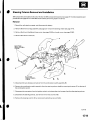
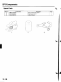
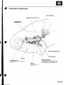
ComponentLocationIndex
GAUGE
ASSEMBLY
UNDER.DASH
FUSE/RELAY
BOX
UNDER.HOOD
FUSE/RELAY
BOX
-,'/.,....
'.,i,
X \ ]
DATA LINK CONNECTORI16P)
TOROUE
SENSOR
STEERINGGEARBOX
SteeringGearboxRemoval,page 17-51
SteeringGearboxOverhaul,page 17-55
SteeringGearboxInstallation,page 17-63
EPSCONTROL
UNIT
EPSControlUnitRemoval/lnstallation,
page17-67
MOTOR
Removal/lnstallation,
page l7-49
17-17
EPSComponents
a
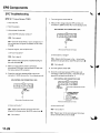
GeneralTroubleshooting
Information
EPSIndicator
Undernormalconditions,
the EPSindicator
comeson when
the ignitlonswitchis turnedto theON(ll)position,
thengoes
Thisindicates
off afterthe engineis started.
thatthebulband
itscircuitareoperating
correctly.
lf thereis anytroublein thesystemaftertheengineis started,
will stayon,andthe powerassistis turned
theEPSindicator
off.
WhenEPSindicator
lightcomeson,thecontrolunit
memorizes
the DTC.In thiscase,thecontrolunitwill not
activate
the EPSsystemaftertheenginestartsagain,but it
keepsthe EPSindicator
on.
WhenDTC12,16,17,18or 67 is storedin thecontrolunit,the
EPSindicator
will stayon untiltheDTCis erased.
Whena
problemis detected
andthe EPSindicator
comeson,thereare
stayson untiltheignitionswitchis
caseswhenthe indicator
goesoff
turned0FF,andcaseswhenthe indicator
whenthesystemreturnsto normal.Eventhough
automatically
thesystemis operating
normally,
the EPSindicator
will come
on underthefollowingconditions:
'1:
Condition
. Thevehiclewastraveling
at least12.4mph(20km/h),then
. A rapid changein vehiclespeedwas detected,then
. Thevehicle(orthevehiclespeedsensorsignal)stoppedfor
at least5 seconds
'l,640rpmorhigherforatleastS
. T h ee n g i n se p e e d
w a ss t i l l
seconds
C o n d i t i o n2 :
Afterthevehicle(orthevehiclespeedsensorsignal)has
yettheenginespeedwasstill
for at least10seconds,
stopped
1,640rpmor higherforat least20seconds.
C o n d i t i o n3 :
When
is280rpmor less,
andthevehicle
istraveling
theengine
speed
at
a speed
of6,2mph(10km/h)
or morefor3 seconds.
To determine
theactualcauseofthe problem,question
the
duringwhichthe problem
customer
abouttheconditions
takingtheaboveconditions
intoconsideration.
occured,
DiagnosticTroubleCode(DTCI
. lf theCPUcannotbeactivated,
or itfails,theEPSindicator
comeson,butthe DTCis notmemorized.
. Thememorycanholdanynumberof DTCS.
However,
when
thesameDTCis detected
morethanonce,the mostrecent
onlyone
DTCis writtenoverthe priorDTC,therefore
occurrence
is memorized.
. TheDTCS
areindicated
repeatedly
untiltheignitionswitchis
turnedOFF.
. lf theDTCis not memorized,the
EPSindicator
blinks.
17-18
. TheDTCS
arememorized
in theEEPRO|(non-volatile
memory)therefore
the memorized
DTCS
cannotbe erased
by disconnecting
the battery.
Perform
thespecified
procedures
to clearDTCS.
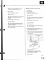
Self-diagnosis
Self-diagnosiscan be classifiedinto two categories:
. I n i t i a l d i a g n o s i sp: e r f o r m e dr i g h ta f t e rt h e e n g i n e
startsand until the EPSindicatorgoes off.
. Regulardiagnosis:performedright after the initial
d i a g n o s i su n t i lt h e i g n i t i o ns w i t c hi s t u r n e dO F F .
The EPScontrol unit performsthe following functions
when a problem is detectedby self-diagnosis;
'1.
T u r n so n t h e E P Si n d i c a t o r .
2. Memorizesthe DTC.
3. Stops power assistand manual steeringoperation
begrns.
NOTE:
. When DTC23 (a problemwith the circuitfor
enginespeedsignal)is detected,the power
a s s i sw
t i l l r e t u r nt o n o r m a lw h e n t h e v e h i c l e
s p e e di s 0 . 6 2m p h ( 1 k m / h )o r a b o v e .
. Fot DfCs 22,23, 64, or 66 the EPSindicatorgoes
off automaticallywhen the system relurnsto
n o r m a l .F o ra l l o t h e rc o d e s t, h e E P Si n d i c a t o r
goes off when the system is OK afterthe ignition
switch is turned from OFFto ON (ll).
Restrictionon PowerAssistOperation
Repeatedextremesteeringforce.such as turning the
steeringwheel continuouslyback-and-forth
with the
vehiclestopped,causesan increaseof power
consumptionin the EPSmotor. The increaseof electric
t h i sh e a t
c u r r e n tc a u s e st h e m o t o rt o h e a tu p . B e c a u s e
adverselyaffectsthe system,the control unit monitors
the electriccurrent of the motor.
When the control unit detectsheat build-upin the motor,
it reducesthe electriccurrentto the motor graduallyto
protectthe system,and it restrictsthe power assist
o p e r a t i o nT. h e E P Si n d i c a t o dr o e sn o t c o m e o n d u r i n g
t h i sf u n c t i o n .
When steeringtorque is not appliedto the steering
wheel, or when the ignition is turned off, and the motor
cools,the control unit will restorethe power assist
graduallyuntil it's fully restored(afterapproximately15
m i n u t e sm a x i m u m ) .
How to TroubleshootEPSDTCs
The troubleshootingflowchart proceduresassumethat
the causeof the problem is still presentand the EPS
indicatoris still on, Followingthe flowchartwhen the
EPSindicatordoes not come on can result in incorrect
diagnosis.
The connectoriliustrationsshow the female terminal
c o n n e c t o rw
s i t h a s i n g l eo u t l i n ea n d t h e m a l et e r m i n a l
connectorswith a double outline.
1. Ouestionthe customeraboutthe conditionswhen
the problem occured,and try to reproducethe
same conditionsfor troubleshooting.Find out
when the EPSindicatorcame on, such as while
t u r n i n g .a f t e r t u r n i n gw, h e n t h e v e h i c l ew a s a t a
certain speed,etc.
2 . T u r nt h e i g n i t i o nO N ( l l ) ,a n d f o l l o wt h e p r o m p t so n
the PGM Testerto displaythe DTC(s)on the screen.
After determiningthe DTC,referto the DTC
TroubleshootingIndex.
NOTE:See the HondaPGM Testeruser's manual
for specificinstructions.
ServiceCheckSignalCircuit Method:
1 . W i t h t h e i g n i t i o ns w i t c hO F F ,c o n n e c t h e H o n d a
P G MT e s t e r( A ) t o t h e 1 6 Pd a t al i n kc o n n e c t o(rD L C )
(B) locatedunderthe dash on the driver'sside of
the vehicle.
2. When the EPSindicatordoes not come on during
the test drive, but troubleshootingis done basedon
the DTC,checkfor looseconnectors,poor terminal
contact.etc in the affectedcircuit,beforeyou start
troubleshooting.
3. After troubleshooting,clearthe DTCand test-drive
the vehicle.Be sure the EPSindicatordoes not
c o m eo n .
How to RetrieveEPSDTCs
Honda PGM Tester Method:
1, With the ignition switch OFF,connectthe Honda
PGM Tester(A)to the 16Pdata link connector(DLC)
(B) locatedunderthe dash on the driver'sside of
thevehicle.
Short the SCScircuitto body ground using the
HondaPGN4Tester.
T u r nt h e i g n i t i o ns w i t c hO N { l l ) .
Recordthe DTC.
(cont'd)
17-19
EPSComponents
GeneralTroubleshootingInformation(cont'dl
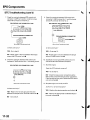
5. The blinkingfrequencyindicatesthe DTC.DTCSare
indicatedby a seriesof long and short blinks.One
l o n g b l i n ke q u a l s1 0 s h o r tb l i n k s A
. d d t h e l o n ga n d
short blinkstogetherto determinethe DTC.After
determiningthe DTC,referto the DTC
TroubleshootingIndex.
The system will not indicatethe DTCunlessthese
conditionsare met:
. Set the front wheels in the straightaheaddriving
position.
. The ignition switch is turned ON (ll).
. The engine is stopped.
. The SCScircuit is shortedto body ground before
the ignition switch is turned ON (ll).
How to ClearEPSDTCs
Honda PGM Tesler Method:
1. With the ignition switch OFF,connectthe Honda
PGM Tester(A)to the 16Pdata link connector(DLC)
( B )l o c a t e du n d e rt h e d a s ho n t h e d r i v e r ' ss i d eo f
the vehicle.
Exampleof DTC23
Long blinks Short blinks
(two times) (three timesl
Turn the ignition switch ON (ll),and clearthe
DTC{s)by following the screenpromptson the
PGM Tester.
NOTE:Seethe Honda PGMTesteruser'smanual
for specificinstructions.
6 . Turn the ignitionswitch OFF.
7 . Disconnectthe Honda PGM Testerfrom the DLC.
17-20
Service Check Signal Circuit Method:
NOTE:Use this procedurewhen the PGM Tester
softwaredoes not matchthe yearlmodelvehicleyou
are working on.
1. With the ignitionswitch OFF,connectthe Honda
PGM Tester(A)to the 16Pdata link connector{DLC)
(B) locatedunderthe dash on the driver'sside of
the vehicle.
1 . Within 4 secondsafter the EPSindicatorgoes off,
returnthe steeringwheel to the straightahead
driving positionagain and releasethe steering
wheel.The EPSindicatorblinkstwice 4 seconds
after releasingthe steeringwheel, indicatingthat
the DTCwas erased.
NOTE:If the EPSindicatordoes not blinktwice, an
error was made in the procedureand the DTCwas
not erased.Turn the ignition switch OFF,and
repeatthe operationfrom step 3.
Turn the ignition switch OFFafterthe EPSindicator
blinkstwice.
9. Disconnectthe Honda PGM Testerfrom the DLC.
10. Performthe DTCcode output operation,and be
sure that the code has been erased.
With the vehicleon the ground,set the front wheels
in the straightaheaddriving position.
Short the SCScircuitto body ground using the
HondaPGM Tester.
4. Turn the ignition switch ON (ll).The EPSindicator
comes on for about 6 seconds.Within 4 secondsof
turning the switch ON, while the EPSindicatoris on,
turn the steeringwheel 45 degreesto the left from
the straightaheaddriving position,and hold the
steeringwheel in that positionuntil the EPS
indicatorgoes off.
Within 4 secondsafterthe EPSindicatorgoes off,
returnthe steeringwheel to the straightahead
driving positionand releasethe steeringwheel.
The EPSindicatorcomes on again 4 secondsafter
releasingthe steeringwheel,
Within 4 secondsafter the EPSindicatorcomes on,
turn the steeringwheel 45 degreesto the left again
and hold it in that position.
The EPSindicatorgoes off after 4 seconds.
17-21
EPSComponents
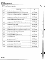
DTCTroubleshootingIndex
DTC
Detection ltem
Note
DTC;12
A problem with voltagefor torque sensorT/SlG
(seepage 17-28)
D T C1: 6
A problemwith averageof voltagefor torque sensorVT3 and VT6
(seepage 17-29)
DTC:17
A problemwith thevoltagefor torquesensor12V powersourceVcc1
( s e ep a g e1 7 - 3 1 )
DTC:18
A problemwith the voltagefor torque sensor5 V power sourceVcc 2
( s e ep a g e1 7 - 3 1 )
DfC:22
A problemwith the averagefor vehiclespeedand enginespeed
( s e ep a g e1 7 - 3 3 )
Excessivechangeof the vehiclespeed sensorsignal
{seepage 17-33)
DTC:23
A problemwith the engine speedsignal circuit
( s e ep a g e1 7 - 3 3 )
DTC:37
A problemwith the circuitfor input motor voltage in the EPScontrol unit
(seepage 17-35)
DTC:41
A problemwith the motor voltage
( s e ep a g e1 7 3 6 )
DfC: 42
A problemwith the motor driven current (opencircuitor short to grounol
(seepage '17-38)
DTC:43
A problem with the motor driven current (shortto power)
( s e ep a g e1 7 - 4 1 )
DTC:45
A problemwith the motor driven current (opencircuitor short to grounol
(seepage 17-38)
DfC: 47
A problemwith the motor relav in the EPScontrol unit
{ s e ep a g e1 7 - 4 2 )
DTC:50
A problem with the CPU in the EPScontrol unit
( s e ep a g e1 7 - 4 3 )
D T C :5 1
A problemwith EEPROM
in the EPScontrolunlt
(seepage 17-43)
DTC:62
Fail-saferelay stuckON
( s e ep a g e1 7 - 4 4 )
DTC:64
A problem with low batteryvoltage
(seepage 17-44)
Fail-saferelay contactfailure
(seepage 17-44)
DTC:66
A problem with the motor driven voltage
{seepage 17 45)
DTC:67
A problemwith the torque sensorl/F circuit
( s e ep a g e1 7 ' 4 5 )
DTC:68
A problemwith the interlockcircuit (torque)
{seepage 17-45)
DTC:69
A p r o b l e mw i t h t h e i n t e r l o c kc i r c u i t( c u r r e n t )
( s e ep a g e1 7 - 4 6 )
17-22
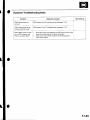
Symptom TroubleshootingIndex
Symptom
Diagnostic procedure
EPSindicatordoes not
come on
EPSlndicatorCircuitTroubleshooting(seepage 17-47)
EPSindicatordoes not go
off and no DTC is stored
EPSIndicatorCircuitTroubleshooting(seepage 17-47)
EPSindicatordoes not stay
on, no DTCis stored,and
there is no power assist
1. Checkthe motor wires betweenthe EPScontrol unit and the
motor for a short to ground. Repairas needed.
2. lf the motor wires are OK, replacethe steeringgearbox
{short in the motor).
Also check fo]
17-23
EPSGomponents
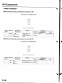
SystemDescription
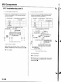
EPSGontrolUnit Inputsand Outputsat ConnectorA (2pl
EPSCONTROLUNIT CONNECTORA {2P)
Wire side of femaleterminals
Termanal Wire color
numbol
Terminalsign
(Terminalnamel
Description
WHT/BLU -' BAT
(Plus
bafterv)
2
8LK
Measurement
Conditions
lqnitiqr switch ON (lll
l Ground Constant
Terminals
Powersourcefor the
actuatormotor
Groundforthe actuator
PG
Voltage
Battery voltage
2-Ground
EPSControlUnit Inputsand Outputsat ConnectorB (2P)
EPSCONTROLUNITCONNECTOB
B {2P}
Wire side of femaleterminals
Terminal Wire colol
numDer
Terminalsign
{Te.mioalname)
Description
Terminals
1
RED
M1
(Motor 1
Driveslhe actuatormotor
1-Ground
2
GRN
M2
Drives the actuator motor
2'Ground
17-24
Measuremenl
Conditions
lqnition switch ON llll
Voltage
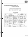
EPSGontrolUnit Inputsand Outputsat ConnestorC (20P1
EPSCONTROLUNITCONNECTOR
C (2OP)
Wire side of femaleterminals
Terminal
Wire color
numbel
2
5
7
Terminalsign
{Terminelname}
Descriplion
Terminals
Measuremeni
Conditions
{lqnitionswitch ON {lll)
T/SGND
Groundfor the torque
(Torquesensorqround)
3-Ground tarttheenqrne
Powersourcefortorque
ORN
vccl
(Voltaqe
common1
Detectstorque sensor
5 Ground Starttheengineand
YEUBED VT6
(Voltaqe
turnthe steerinowheel
stonal
torque6)
ON
Drivesthe EPSindicator
6 Ground E P S
YEUBLU
(Warninqlamp)
lidhr
uTltnotcatol
Raisethe vehicleoff the
Detectsthe vehiclespeed
BLUAVHT VSP
( V e h i c l es p e e d p u l s e i
groundandspinthe
inputsignalfor the speed
sensoror the ECM(4 pulse/
Voltage
PNK
BRN
10
YEL
11
GRN//EL
SCS
checksiqnal)
{Servjco
IG1
llqnition1
vcc2
Detectsservicecheck
Drivesthetorquesensor
Batteryvoltage
on switchON (ll)
on switchOFF
1'l-Ground tan the enoine
Battervvoltaqe
About5V
on switch OFF
8LU/ORN VT3
Detectstorque sensor
YEUBLK T/SIG
(TorquesensorF/S
Detectstorque sensor
srgnal
(Voltaoe
toroue3)
OV
Banervvoltaqe
Alternating
voltageabout
OV 5V OV-5V
8-Ground SCSnot grounded
Powersourcefor activating 10-Ground
(Voltaqe
common2)
Ba$ervvoltaqe
OV
About
1'l
LT GRN/
B IK
19
BLU
Providespower steering
PSW
iPowersteerinoswitch) switchsional
Detectsthe enginepulse
NEP
20
GRY
DIAG-H
with
Communications
HondaPGNITester
About
13-GroundStarttheengineand
trrrnthe steerinowheel 5 - 0 v
Momentarily
5V
15-GroundStarttheengine
0-12V
l7-Ground Starttheengineand
nrrnthe steerinowheel
19-GroundStarttheengine,and let
;t idte
5V
20-Ground PGMTesternot
17-25
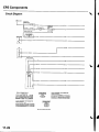
EPSComponents
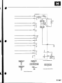
CircuitDiagram
\
\
SPE€DSENSOR
3P CONNECTOR
@
GAUGEASSEMATY22PCONNECTOR
TOFOUESENSOR
6P CONNECTOR
lli2l3F
r;T;T-I
(=J_:_LvJ
Wn. !ide ot f.m.l€ r.fmin.ls
17-26
GAUGEASSEMBLY22PCONNECTON
a
OATA !IN( CONN€CTOA(T6P)
EPSCOI{IFOIUNIT
cou{EcToR A (2P)
F-l
vTTrvaEvnrv
A
EPSCONTNOLUNIT
co|lNEcTofi 8 {2P}
| l l
wwzna
MOTOF
CONNECTOR
riTt
t2)
T.rmin.l.id.
oll.m.l.r.rmin.l.
Wir. !.le ol l.m.l. t.tman.r.
17-27
EPSComponents
DTCTroubleshooting
DTC12: TorqueSensorT/SIG
1 . C l e a rt h e D T C .
1 . Turn the ignition switch ON (ll).
8 . Measurethe voltage betweenEPScontrol unit
c o n n e c t oC
r ( 2 0 P ) t e r m i n aNl o . 1 5 a n d b o d y g r o u n d .
2 . S t a nt h e e n g i n e .
3. Wait at least 10 seconds.
Does the EPS indicatot come on?
EPSCONTROL
UNITCONNECTOR
C (2OP)
2 3
YES Go to step 4.
5 6 1 8
0
T/SIG
{YEL/BLK)
NO Checkfor loosewires or poor connections.lf
the connectionsare good, the system is OK at this
time.l
4 . Stop the engine,and verify the DTC.
Wire side ot lemaleterminals
ls DTC12 indicated?
I s there battery v oltage?
YES Go to slep 5.
NO-Perform the appropriatetroubleshootingfor
the code indicated.t
YES-Repair short to power in the + circuitwire
betweenthe torque sensorand EPScontrol unit.l
NO Go to step 9.
5 . Make sure the ignitionswitch is OFF,then
disconnectEPScontrol unit connectorC (20P)and
the torque sensor6P connector.
Checkfor continuitybetweenEPScontrol unit
c o n n e c t oC
r ( 2 0 P ) t e r m i n aNl o . 1 5 a n d b o d y g r o u n d .
EPSCONTROL
UNITCONNECTOR
C {2OP)
\
9 . Turn the ignition switch OFF.
1 0 . Checkfor continuitybetweenEPScontrol unit
connectorC (20P)terminal No. 15 and the torque
sensor6P connectorterminal No. 4.
EPSCONTROL
UNITCONNECTOR
C (2OPI
T/SIG
(YEL/BLK)
W i r es i d eo f f e m a l et e r m i n a l s
TOROUE
SENSOR
6PCONNECTOR
T/SIG
(YEL/BLK)
Wire side of femaleterminals
Wire side ot femaleterminals
ls therecontinuity?
ls there continuity?
YES- Repairshortto bodygroundin thewire
betweenthetorquesensorandEPScontrolunit.l
YES Go to step 1'1,
NO Go to step7.
NO Repairopen in the wire betweenthe torque
sensorand the EPScontrol unit.I
17-28
'I
1 . Substitutea known-goodEPScontrol unit, and
connectthe all disconnectedconnectors.
1 2 .Start the engine.
DTC16:TorqueSensorVT3andW6
1 . C l e a rt h e D T C .
2. Startthe engine.
3 . W a i t a t l e a s t1 0 s e c o n d s .
Does the EPS indicator come on?
Does the EPS indicator come on?
YES Go to step 13.
YES Go to step 4.
NO Checkfor loose EPScontrol unitconnectors.lf
necessary,replacethe EPScontrol unit and
retest.l
NO Checkfor loosewires or poor connnections.lf
the connectionsare good,the system is OK at this
time.l
1 3 .Stop the engine,and verify the DTC.
4. Stop the engine,and verify the DTC.
ls DTCl2 indicated?
ls DTC16 indicated?
YES Checkfor loosetorque sensorconnectors.
lf necessary,substitutea known-goodsteering
gearboxand recheck.l
NO-Perform the appropriatetroubleshootingfor
the code indicated.!
YES-Go to step 5.
NO Performthe appropriatetroubleshootingfor
the code indicated.t
5. Make sure the ignition switch is OFF,then
disconnectEPScontrol unit connectorC (20P)and
the torque sensor6P connector.
6, Checkfor continuitybetweenthe appropriateEPS
control unit connectorC (20P)terminal and body
ground (seetable).
Terminalname
C
EPScontrolunitconnector
terminalNo.
Vccl
3
Vcc2
VT3
VT6
11
13
T/S GND
5
2
EPSCONINOTUNITCONNECIOR
C (2OP)
W re s d€ oltemalelermi.als
ls there continuity?
YES- Repairshort to body ground in the
appropriatesensorcircuit betweenthe torque
sensorand EPScontrol unit,!
NO Go to step7.
{cont'd)
17-29
EPSComponents
I
DTCTroubleshooting(cont'd)
7 . T u r nt h e i g n i t i o ns w i t c hO N ( l l ) .
9 . Turn the ignition switch OFF.
8 . Measurethe voltage betweenthe appropriateEPS
control unit connectorC (20P)terminal and body
ground (seetable).
Terminalname
Vccl
EPScontrol
unitconnector
C
t e r m i nN
a lo .
3
Vcc2
VT3
VT6
11
T/S GND
2
13
5
EPSCONTROLUNITCONNECTOR
C {2OP}
1 0 . Checkfor continuitybetweenthe appropriateEPS
control unit connectorC {20P)terminal and the
torque sensorterminal (seetable).
T e r m i n a l TorqueSensor EPScontrol
name
t e r m i n aNl o , unitconnector
C t e r m i n aNl o .
Vccl
2
3
Vcc2
3
11
'l
't3
VT3
VT6
6
5
6
T/S GND
2
TOROUESENSOR6PCONNECTOR
Vccz
(GRN/YELI
Wire side of
f e m a l et e r m i n a l s
VT6 {YEL/RED)
T/S GND {PNK)
Wire side of femaleterminals
EPSCONTROLUNIT
CONNECTOR
C I2OP)
VT6{YEL/RED}
\
ls thete battery voltage?
YES Repairshon to power in the + circuitwire
betweenthe EPScontrol unit and torque sensor.l
NO Go to step 9.
Wire side of femaleterminals
ls therecontinuty?
Y E S G ot o s t e p1 1 .
NO Repairopenin the appropriate
torquesensor
wirecircuitbetweenthe EPScontrolunitandthe
t o r q u es e n s o r . l
\
17-30
1 1 .Substitutea known-goodEPScontrol unit, and
reconnectthe disconnectedconnectors.
't2.
DTC17: TorqueSensorVccl
DTC18:TorqueSensorVcc2
Start the engine.
1 . C l e a rt h e D T C .
Does the EPS indicator come on?
2 . S t a r tt h e e n g i n e .
YES Go to step 13.
3. Wait at least 10 seconds.
NO Checkfor looseor poor connectionsat the
EPScontrol unit and the torque sensorconneclors.
lf the connectionsare good, replacethe EPScontrol
u n i ta n d r e c h e c k . I
1 3 .Stop the engine,and verify the DTC.
ls DTC16 indicated?
Does the EPS indicator come on?
YES Go to step 4.
NO Checkfor loosewires or poor connections.lf
the connectionsare good, the system is OK at this
time.I
YES Replacethe steeringgearboxand recheck.l
4 . Stop the engine,and verify the DTC.
NO Performthe appropriatetroubleshootingfor
the code indicated.l
Is DTCl7 or DTCl8 indicated?
YES Go to step 5.
NO Do the troubleshootingfor the DTc
indicated.I
Make sure the ignition switch is OFF,then
disconnectEPScontrol unit connectorC (20P)and
the torque sensor6P connector.
Checkfor continuitybetweenEPScontrol unit
c o n n e c t oC
r ( 2 0 P ) t e r m i n aNl o . 3 a n d b o d y g r o u n d .
UNITCONNECTOR
C (2OP)
EPSCONTROL
Wiresideo{ femaleterminals
ls there continuity?
Y E S R e p a i rs h o n t o b o d y g r o u n di n t h e w i r e
betweenthe torque sensorand EPScontrol unit.I
NO Go to step 7.
(cont'd)
17-31
EPSComponents
DTCTroubleshooting(cont'dl
7. Checkfor continultybetweenEPScontrol unit
c o n n e c t oC
r ( 2 0 P t)e r m i n a lN o . 3 a n d t h e t o r q u e
sensor6P connectorterminal No. 2.
EPSCONTROL
UNITCONNECTOR
C I2OP)
\
9. Checkfor continuitybetweenEPScontrol unit
connectorC {20P)terminal No. 11 and the torque
sensor6P connectorterminal No. 3.
EPSCONTROL
UNITCONNECTOR
C (2OP}
Vcc2(GRN/YEL)
Wire side ol lemale terminals
Wire side of femaleterminals
ls thete continuity?
ls therc continuity?
YES Go to step 8.
YES-Go to step 10.
NO Repairopen in the wire betweenthe torque
s e n s o ra n d E P Sc o n t r o lu n i t . I
NO Repairopen in the wire betweenthe torque
sensorand EPScontrol unit.l
8 . Checkfor continuitybetweenEPScontrol unit
c o n n e c t oC
r ( 2 0 P t)e r m i n a lN o . 1 1 a n d b o d y g r o u n d .
EPSCONTROL
UNITCONNECTOR
C (2OP)
1 0 .Substitutea known-goodEPScontrol unit, and
connectall the disconnectedconnectors.
1 1 .Start the engine.
Does the EPS indicator come on?
2 3
lvcc2
5 6 1 8
0
{GRN/YEL)
Wire side of femaleterminals
YES Go to step 12.
NO Checkfor looseor poor connectionsat the
EPScontrol unit and the torque sensorconnectors.
lf the connectionsare good, replacethe EPScontrol
u n i ta n d r e c h e c k . l
12. Stop the engine,and verity the DTC.
ls DTC17 or DTC18 indicated?
ls therecontinuity?
YES-Replace the steeringgearboxand recheck.l
YES Repairshortto bodygroundin thewire
betweenthetorquesensorandEPScontrolunit.t
NO Goto step9.
17-32
NO Performthe appropriatetroubleshootingfor
the code indicated.l
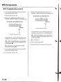
DTC22: VehicleSpeedSensorSignal
3 . Blockthe rearwheels and raisethe vehicle,and
make sure it is securelysupported.
DTC23: EngineSpeedSignal
4 . T u r nt h e i g n i t i o ns w i t c hO N ( l l ) .
NOTE:
. lf the MIL indicatoris ON, troubleshootthe PGIVI-Fl
systemfirst.
. Eventhough the system is operatingnormally,the
EPSindicatorwill come on underthe following
conditions.
- C o n d i t i o n1 :
. The vehiclewas travelingat least '12.4mph
(20 km/h),then
. A rapld changein vehiclespeedwas detected,
then
. T h e v e h i c l e( o rt h e v e h i c l es p e e ds e n s o rs i g n a l )
stoppedfor at least5 seconds,and
. The engine speedwas still 1,640rpm or higherfor
at least5 seconds
- Condition2:
After the vehicle(or the vehiclespeedsensor
signal)has stoppedfor at least10 seconds,yetthe
e n g i n es p e e dw a s s t i l l 1 , 6 4 0r p m o r h i g h e rf o r a t
least20 seconds.
- Condition3:
W h e nt h e v e h i c l es p e e di s 1 0 k m / h ( 6 . 2m p h )o r
a b o v ea n d t h e e n g i n ei s r u n n i n ga t 2 8 0 r p m o r
below for 3 seconds.
1. Startthe engineand checkthe tachometer.
ls the tachometer working correctly?
5 . Blockthe right front wheel, and slowly rotatethe
left front wheel, and measurethe voltage between
E P Sc o n t r o lu n i tc o n n e c t oC
r ( 2 0 P ) t e r m i n aNl o . 7
a n d b o d yg r o u n d .
EPSCONTROL
UNITCONNECTOR
C {2OP)
Wire side of femaleterminals
Does the voltagepulse 0 V and 5 V?
YES Go to step 6.
NO Repairopen in the wire betweenthe EPS
control unit and the VSS. lf the wire is OK,checkfor
a loose or poor connectionsat the EPScontrol unit.
lf necessary,substitutea known-goodEPScontrol
u n i t ,a n d r e c h e c k . l
YES- Go to step 2.
N O - G o t o s t e p9 .
2. Test-drivethe vehicleabove 15 km/h {9.3mph).
ls the speedometerworking correctly?
YES Go to step 3.
NO-Perform the speedometersystem
troubleshooting{see page22-651.a
(conr'd)
17-33
EPSGomponents
DTCTroubleshooting(cont'dl
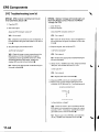
Turn the ignition switch OFF,and disconnectEPS
control unit connectorC (20P).
7 . Startthe engine,and let it idle.
11. Measurethe voltage betweenEPScontrol unit
c o n n e c t oC
r ( 2 0 P ) t e r m i n aNl o . 1 9 a n d b o d y g r o u n d .
EPSCONTROLUNITCONNECTOR
C {2OPI
8 . Measurethe voltage betweenEPScontrol unit
c o n n e c t oC
r { 2 0 P t) e r m i n a lN o . 1 9a n d b o d y g r o u n d .
EPSCONTROL
UNITCONNECTOR
C {2OP)
Wiresideof femaleterminals
ls there about 6 V at idle? (With the metet set tor
trequency, is therc 33 Hz per 1,000 engine rpn?)
Wire side of {emaleterminals
ls there about 6 V at idle? (With the meter set lol
t requency,is there 33 Hz per 1,000engine rpm?)
YES Checkfor loose EPScontrol unitconnectors.
lf necessary,substitutea known-goodEPScontrol
u n i ta n d r e c h e c k . I
NO Go to step
YES Checkfor loose EPScontrol unit connectors.
lf necessary,substitutea known-goodEPScontrol
u n i ta n d r e c h e c k . l
'12.
1 2 .Turn the ignition switch OFF.
1 3 .Disconnectthe ECMconnectorE (31P)connector.
NO Repairopen in the wire betweenthe EPS
c o n t r o lu n i ta n d t h e E C M . I
9 . Turn the ignition switch OFF,and disconnectEPS
control unit connectorC (20P).
1 0 .Startthe engine,and let it idle.
!
17-34
'14.
Checkfor continultvbetweenEPScontrol unit
c o n n e c t oC
r ( 2 0 P ) t e r m i n aNl o . 1 9 a n d E C M
connectorE (31P)terminal No. 26.
ECMCONNECTOR
E {31PI
DTC37: EPSControlUnitInternal
Circuit
(lnputCircuitForMotorVoltage)
1 . C l e a rt h e D T C .
2. Startthe engine.
3. Turn the steeringwheel from lock-to-lockseveral
times, and wait 10 secondsor more.
Does the EPS indicator come on?
YES Go to step 4.
NO Checkfor loosewires or poor connections.lf
the connectionsare good,the system is OK at this
trme.l
ls thete continuity?
4. Stop the engine,and verify the DTC.
YES-Go to step 15.
ls DTC 37 indicated?
N O - R e p a i r o p e n i n t h e w i r e b e t w e e nt h e E P S
c o n t r o lu n i ta n d E C M . I
Y€S Checkfor loose EPScontrol unit conneclors.
lf necessary,substitutea known-goodEPScontrol
u n i ta n d r e c h e c k . l
1 5 . Disconnectthe gauge assembly22Pconnector.
Checkfor continuitybetweenEPScontrol unit
c o n n e c t oC
r ( 2 0 P ) t e r m i n aNl o . 1 9 a n d b o d y g r o u n d ,
NO Performthe appropriatetroubleshootingfor
the code indicated.l
EPSCONTROL
UNITCONNECTOR
C (2OP}
Wiresideof femaleterminals
ls there continuity?
Y E S R e p a i rs h o r t t ob o d y g r o u n di n t h e w i r e
betweenthe EPScontrol unit, the test tachometer
connector,the gaugeassembly,and the ECM.I
NO Checkfor loose ECMcontrol unit connectors.
lf necessary,substitutea known-goodECMcontrol
u n i ta n d r e c h e c k . I
17-35
EPSComponents
.l
DTCTroubleshooting(cont'dl
DTC41: VoltageForMotor
7. Checkfor continuitybetweenEPScontrol unit
c o n n e c t oB
r ( 2 P ) t e r m i n aNl o . 2 a n d b o d y g r o u n d .
1 . C l e a rt h e D T C .
EPSCONTROLUNITCONNECTOR
B I2P)
2 . S t a r tt h e e n g i n e .
3. Turn the steeringwheel from lock-to-lockseveral
times, and wait 10 secondsor more,
Tit
M2 {GRN)FJ
-r
Does the EPS indicator come on?
o)
YES-Go to step 4.
I
T
NO Checkfor loosewires or poor connections.lf
the connectionsare good,the system is OK at this
time.l
4. Stop the engine,and verify the DTC.
ls DTC 41 indicated?
Wiresideof femaleterminals
ls there continuity?
Y E S - R e p a i rs h o r tt o b o d y g r o u n di n t h e G R Nw i r e
betweenthe EPScontrol unit and the motor,l
YES Go to step 5.
NO Go to step 8.
NO Performthe appropriatetroubleshootingfor
t h e c o d ei n d i c a t e d . l
5. Make sure the ignition switch is OFF,then
disconnectEPScontrol unit connectorB (2P)and
the motor 2P conneclor.
Checkfor continuitybetweenEPScontrol unit
c o n n e c t oB
r ( 2 P ) t e r m i n aNl o . 1 a n d N o . 2 .
B {2P)
EPSCONTROL
UNITCONNECTOR
6. Checkfor continuitybetweenEPScontrol unit
c o n n e c t oB
r ( 2 P )t e r m i n a lN o . 1 a n d b o d y g r o u n d .
B {2P}
EPSCONTROLUNIT CONNECTOR
M2 (GRNI
M1 (RED}H
F---t||
Itr
(f))
T
,L
Wiresideof femaleterminals
ls there continuity?
YES Repairshort to body ground in the REDwire
betweenthe EPScontrol unit and the motor.!
N O - G o t o s t e p7 .
17-36
Wiresideof femaleterminals
ls there continuity?
YES Repairshort betweenthe REDand GRN
wires in the motor circuit betweenthe EPScontrol
u n i t a n dt h e m o t o r . l
NO Go to step 9.
\
9. Turn the ignition switch ON (ll),and measurethe
voltagebetweenEPScontrol unit connectorB (2P)
terminal No. 1 and body ground
EPSCONTROLUNITCONNECTOR
B (2P)
1 1 .T urn the ignition switch is OFF.
Substitutea known-goodEPScontrol unit, and
connectall the disconnectedconnectors.
1 3 .Start the engine,and turn the steeringwheel from
lockto lock severaltimes.
M1 IREDI
H
r-_-1 ||
,<.)\
uL,/
Y
tr
I
WiresideoI femaleterminals
Does the EPS indicator come on?
Y E S - G o t o s t e p1 4 .
NO-Check for loose or poor connectionsatthe
EPScontrol unit and the motor connections.lfthe
connectionsare good, replacethe EPScontrol unit
andrecheck.l
1 4 . S t o pt h e e n g i n e a
, n d v e r i t yt h e D T C .
Is there battety voltage?
ls DTC 41 indicated?
YES Repairshort to power in the + circuitwire
betweenthe EPScontrol unit and the motor.I
YES Replacethe steeringgearboxmotor and
recheck.l
N O - G o t o s t e p1 0 .
1 0 .Measurethe voltagebetweenEPScontrol unit
NO Performthe appropriatetroubleshootingfor
t h e c o d ei n d i c a t e d . l
c o n n e c t oB
r ( 2 P ) t e r m i n aNl o . 2 a n d b o d y g r o u n d .
EPSCONTROL
B (2P)
UNITCONNECTOR
razrcnrrrr
l{. I
l-t
I
(v)
Y
I
Wire side of femaleterminals
ls there battery voltage?
YES-Repair shortto power in the - circuitwire
betweenthe EPScontrol unit and the motor.!
N O G o t o s t e p1 1 .
17-37
EPSComponents
DTCTroubleshooting(cont'd)
DTC42,45: MotorDrivenCurrent
{
7. Checkfor continuitybetweenEPScontrol unit
c o n n e c t oB
r ( 2 P l t e r m i n aNl o . 2 a n d b o d y g r o u n d .
1. Clearthe DTC.
EPSCONTROLUNITCONNECTOR
B I2PI
2. Start the engine.
3. Turn the steeringwheel from lock-to-lockseveral
t i m e s ,a n d w a i t 1 0 s e c o n d so r m o r e .
r',rz
tcnnrt
ll
-](o)
Does the EPS indicator come on?
T
YES- Go to step 4.
I
NO-Check for loosewires or poor connections.lf
the connectionsare good, the system is OK at this
time.I
Wiresideof femaleterminals
Stop the engine,and verify the DTC.
lsthere continuity?
ls DTC 42 or 45 indicated?
YES Repairshort to body ground in the GRNwire
betweenthe EPScontrol unit and the motor.l
YES-Go to step 5.
NO Go to step 8.
NO- Performthe appropriatetroubleshootingfor
t h e c o d ei n d i c a t e d . I
M a k es u r et h e i g n i t i o ns w i t c hi s O F F ,t h e n
disconnectEPScontrol unit B connector(2P)and
the motor 2P connector.
Checkfor continuitybetweenEPScontrol unit
c o n n e c t oB
r ( 2 P )t e r m i n a lN o . 1 a n d N o . 2 .
EPSCONTROL
UNITCONNECTOR
B {2P)
6 . Checkfor continuitybetweenEPScontrol unit
c o n n e c t oB
r ( 2 P ) t e r m i n aNl o . 1 a n d b o d y g r o u n d .
EPSCONTROL
UNITCONNECTOR
B I2P)
M2 {GRN)
M1 IRED}H
I
f2-l
W i r es i d eo f f e m a l et e r m i n a l s
(C))
T
I
Wire side of femaleterminals
ls there continuity?
YES Repairshort to body ground in the REDwire
betweenthe EPScontrol unit and the motor,I
N O - G o t o s t e p7 .
17-38
ls there continuity?
YES Repairshort betweenthe REDand GRN
wires in the motor circuit betweenthe EPScontrol
u n i ta n d t h e m o t o r . l
NO Go to step 9.
9. Turn the ignition switch ON (ll),and measurethe
voltage betweenEPScontrol unit connectorB (2P)
t e r m i n a lN o . I a n d b o d y g r o u n d .
EPSCONTROLUNITCONNECTOR
B (2PI
M1{RED}H
T-----l | |
(v)
11. Checkfor continuitybetweenEPScontrol unit
connectorB (2P)terminal No. 1 and the motor 2P
connectorterminal No. 2.
EPSCONTROLUNIT
B 12P)
CONNECTOR
MOTORCONNECTOR
{2PI
M1 IRED)
lil
M1 (RED}
I
I
Wiresideo{ Iemaleterminals
ls there battety voltage?
YES-Repair short to power in the + circuitwire
betweenthe EPScontrol unit and motor.l
Wire side of femaleterminals
ls therecontinuity?
YES-Go to step'12.
NO-Repairopenin the REDwire betweenthe EPS
controlunitandthe motor.l
NO Go to step 10.
1 0 .Measurethe voltage betweenEPScontrol unit
c o n n e c t oB
r { 2 P } t e r m i n aNl o . 2 a n d b o d y g r o u n d .
EPSCONTROL
UNITCONNECTOR
B (2P}
mzrcnrur
ll-l
A
(v)
Y
I
W i r es i d eo f f e m a l et e r m i n a l s
ls there battery voltage?
Y E S R e p a i rs h o r tt o p o w e ri n t h e + c i r c u i t w i r e
betweenthe EPScontrol unit and the motor.a
N O - G o t o s t e p1 1 .
(cont'd)
17-39
EPSGomponents
L
DTGTroubleshooting(cont'd)
12. Checkfor continuitybetweenEPScontrol unit
c o n n e c t oB
r ( 2 P ) t e r m i n aNl o . 2 a n dt h e m o t o r2 P
c o n n e c t otre r m i n a lN o . 1 .
EPSCONTROLUNIT
CONNECTORB I2PI
MOTORCONNECTOR
{2P)
15. Stop the engine,and verify the DTC.
ls DTC 42 or 45 indicated?
YES Replacethe steeringgearboxmotor and
recheck.l
NO Performthe appropriatetroubleshootingfor
the code indicated.l
M2 IGRN)
Wire side of femaleterminals
ls there continuity?
Y E S - G o t o s t e p1 3 .
NO-Repair open in the GRNwire betweenthe EPS
control unit and the motor.l
Checkfor loosewires or poor connections,if the
connectionsare good. substitutea known-good
EPScontrol unit, and connectallthe disconnected
connectors.
1 4 . Startthe engine,and turn the steeringwheel from
lockto lock severaltimes.
Does the EPS indicatot come on?
YES Go to step 15.
NO Checkfor loose EPScontrol unitconnectors.lf
necessary,replacethe EPScontrol unit and
recheck.a
17-40
(
DTCtli|: MotorDrivenCurrentis Excessively
Hish
1 . C l e a rt h e D T C .
8. Measurethe voltagebetweenEPScontrol unit
c o n n e c t oB
r ( 2 P ) t e r m i n aNl o . 2 a n d b o d y g r o u n d .
EPSCONTROL
UNITCONNECTOR
B I2PI
2. Startthe engine.
3. Turn the steeringwheel from lock-to-lockseveral
'10
times, and wait
secondsor more.
Til
M2tcRNl F-l
f---1 z I
(v)
Does the EPS indicator come on?
Y
I
YES Go to step 4.
NO-Check for loosewires or poor connections.lf
the connectionsare good,the system is OK at this
ttme.I
W i r es i d eo f f e m a l et e r m i n a l s
ls there battety voltage?
4. Stop the engine,and verify the DTC.
ls DTC 43 indicated?
YES- Repairshort to power in the - circuitwire
betweenthe EPScontorl unit and the motor.!
YES Go to step 5.
NO-Go to step 9.
NO-Perform the appropriatetroubleshootingfor
the code indicated.I
5. Make sure the ignition switch is OFF,then
disconnectEPScontrol unit connectorB (2P)and
the motor 2P connector.
9 . Turn the ignition switch OFF.
1 0 . Checkfor continuitybetweenEPScontrol unit
c o n n e c t oB
r ( 2 P )t e r m i n a l sN o . 1 a n d N o . 2 .
EPSCONTROL
UNITCONNECTOR
B {2P)
6. Turn the ignition switch ON (ll).
7. Measurethe voltage betweenEPScontrol unit
'1
c o n n e c t oB
r ( 2 P ) t e r m i n aNl o . a n d b o d y g r o u n d .
EPSCONTROLUNITCONNECTOR
B {2P}
M2 {GBN)
M 1 { R E o )H
T------t
I I
Itr
(v)
T
-L
Wiresideot Iemaleterminals
Wire side of femaleterminals
ls there continuity?
YES Repairshort betweenthe GRN and RED
wires in the motor circuitbetweenthe EPScontrol
u n i ta n d t h e m o t o r . l
N O G o t o s t e p1 1 .
ls therc battery voltage?
YES Repairshort to power in the + circuitwire
betweenEPScontrol unit and motor.l
N O - G o t o s t e p8 .
( c o n td )
17-41
EPSComponents
DTCTroubleshooting(cont'dl
1 1 .Substitutea known-goodEPScontrol unit, and
connectall the disconnectedconnectors.
1 2 .Start the engine,and turn the steeringwheel from
(
DTC47: EPSControlUnitlnternalCircuit
(PowerRelay)
1. Clearthe DTC.
lockto lock severaltimes.
2. Startthe engine.
Does the EPS indicator come on?
Does the EPS indicator come on?
YES Go to step 13.
NO -Check for loose or poor connectionsat the
EPScontrol unit and the motor connections.lf the
connectionsare good, replacethe EPScontrol unit
and recheck.l
1 3 .Stop the engine,and verity the DTC.
YES-Go to step 3,
NO-Check for loosewires or poor connections,lf
the connectionsare good, the system is OK at this
time.I
3. Stop the engine,and verify the DTC.
ls DTC 43 indicated?
ls DTC 47 indicated?
YES-Replacethe steeringgearboxmotor and
recheck.tl
YES Checkfor loose EPScontrol unit connectors.
lf necessary,substitutea known-goodEPScontrol
u n i ta n d r e c h e c k . l
NO-Perform the appropriatetroubleshootingfor
the code indicated.l
17-42
NO Performthe appropriatetroubleshootingfor
the code indicated.I
DTC50: EPSControlUnit InternalCircuit
(CPUor Microcomputer)
DTC51: EPSControlUnitInternalCircuit
(EEPROM)
1. Clearthe DTC.
1 . C l e a rt h e D T C .
2. Start the engine.
2. Start the engine.
Does the EPS indicator come on?
Does the EPS indicatot come on?
YES Go to step 3.
YES-Go to step 3.
NO Checkfor loosewires or poor connections.lf
the connectionsare good. the system is OK at this
t i m e .t
NO-Check for loosewires or poor connections.lf
the connectionsare good, the system is OK at this
time.I
3. Stop the engine,and verify the DTC.
3. Stop the engine,and verify the DTC.
ls DTC 50 indicated?
ls DTC 51 indicated?
YES-Check for looseor poor connectionsat the
EPScontrol unit connections.lf the connectionsare
good, substitutea known-goodEPScontrol unit. lf
the symptom/indicationgoes away, replacethe
original EPScontrol unit.l
YES-Check for looseor poor connectionsat the
EPScontrol unit connections.lf the connectionsare
good. substitutea known-goodEPScontrol unit. lf
the symptom/indicationgoes away, replacethe
original EPScontrol unit.!
NO Performthe appropriatetroubleshootingfor
the code indicated.t
NO Performthe appropriatetroubleshootingfor
the code indicated.t
17-43
EPSComponents
(cont'dl
DTCTroubleshootang
DTC62: EPSControlUnit InternalCircuit
(Fail-safe
RelayStuckON)
'1.
(
Low
DTC64: BatteryVoltageis Excessively
(Fail-safe
RelayContactFailureandMotor
VoltageFallOff)
Clearthe DTC.
2. Startthe engine.
1 . C l e a rt h e D T C .
2. Startthe engine.
Does the EPS indicator come on?
Does the EPS indicatot come on?
YES-Go to step 3.
YES Go to step 3.
NO-Check for loosewires or poor connections.lf
the connectionsare good, the system is OK at this
time.I
NO Checkfor loosewires or poor connections.lf
the connectionsare good,the system is OK at this
trme.l
3. Stop the engine,and verify the DTC.
3. Stop the engine,and verify the DTC.
ls DTC 62 indicated?
ls DTC 64 indicated?
YES-Check for loose or poor connectionsat the
EPScontrol unit. lf the connectionsare good,
substitutea known-goodEPScontrol unit. lf the
symptom/indicationgoes away, replacethe
originalEPScontrol unit and recheck.l
YES Go to step 4.
NO-Perform the appropriatetroubleshootingfor
the code indicated.t
NO Performthe appropriatetroubleshootingfor
the code indicated.
'18(604)
4. Checkthe No.
fuse in the under-hoodfuse/
relay box, and reinstallthefuse if it is OK.
Is the f use OK?
YES Go to step 5.
NO Replacethe fuse and recheck.l
5. DisconnectEPScontrol unit connectorA (2P).
6. Measurethe voltage betweenEPScontrol unit
c o n n e c t oA
r ( 2 P )t e r m i n a lN o . 1 a n d b o d y g r o u n d .
-Blwt{r/Bl.urH
l
\9
I
ls there battety voltage?
YES- Checkfor loose or poor connectionsat the
EPScontrol unit connectors,and checkfor a poor
ground at G 151. lf necessary,substitutea knowngood EPScontrol unit and recheck.l
NO Repairopen in the WHT/BLUwire between
t h e N o . 1 8 ( 6 0 , 4 ) f u saen d E P Sc o n t r o lu n i t . l
17-44
DTC66,68: EPSControlUnitlnternalCircuit
DTC67: TorqueSensorl/FCircuit
1 . C l e a rt h e D T C .
1. Clearthe DTC.
2. Start the engine.
2 . S t a r tt h e e n g i n e .
3. Turn the steeringwheel from lock-to-lockseveral
times, and wait 10 secondsor more.
3. Turn the steeringwheelfrom lock-to-lockseveral
times, and wait 10 secondsor more.
Does the EPS indicator come on?
Does the EPS indicator come on?
YES-Go to step 4.
YES-Go to step 4.
NO-Check for loosewires or poor connections.lf
the connectionsare good.the system is OK at this
time.l
NO Checkfor loose wires or poor connections.lf the
connectionsare good, the system is OK at this time. !
4. Stop the engine,and verify the DTC.
4. Stop the engine.and verify the DTC.
ls DTC 67 indicated?
ls DTC 66 or 68 indicated?
YES-Check for looseor poor connectionsat the
EPScontrol unit. lf the conneclionsare good,
substitutea known-goodEPScontrol unit. lf the
symptom/indicationgoes away, replacethe
original EPScontrol unit and recheck.I
NO Performthe appropriatetroubleshootingfor
the code indicated.t
YES Checkfor looseor poor connectionsat the
EPScontrol unit. lf the connectionsare good,
substitutea known-goodEPScontrol unit. lf the
symptom/indicationgoes away, replacethe
original EPScontrol unit and recheck.!
NO-Perform the appropriatetroubleshootingfor
the code indicated.I
17-45
EPSComponents
DTCTroubleshooting(cont'd)
DTC69: EPSControlUnit InternalCircuit
1 . C l e a rt h e D T C .
2. Startthe engine.
3. Turn the steeringwheel from lock-to-lockseveral
times, and wait 10 secondsor more,
Does the EPS indicator come on?
YES Go to step 4.
NO-Check for loosewires or poor connections.lf
the connectionsare good, the system is OK at this
time.l
4. Stop the engine,and verify the DTC.
ls DTC 69 indicated?
YES-Check for loose or poor connectionsat the
EPScontrol unit. lf the connectionsare good,
substitutea known-goodEPScontrol unit. lf the
symptom/indicationgoes away, replacethe
original EPScontrol unit and recheck.l
NO- Performthe appropriatetroubleshootingfor
the code indicated.l
17-46
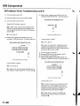
EPSIndicatorCircuitTroubleshooting
1 . Turn the ignitionswitch ON (ll),startthe engine,
and watch the EPSindicator.
5. Turn the ignition switch OFF.
6. DisconnectEPScontrol u n it connectorC (20P).
Does the EPS indicator come on?
7 . T u r nt h e i g n i t i o ns w i t c hO N ( l l ) .
YES lf the EPSindicatorcomes on and goes off, it's
OK. lf the EPSindicatorstayson or blinks.go to
s t e p1 2 .
8. ConnectEPScontrol unit connectorC (20P)
terminal No. 6 to body ground with a jumper wire.
NO Go to step 2.
EPSCONTBOLUNIT CONNECTOBC {2OP)
Turn the ignition switch OFF,then ON (ll) again,
and watch the brakesystem indicator,
Does the brake system indicator come on?
YES-Go to step 3.
W i r e s d € o f l e m a l e 1 6 r m i n as
NO Repairopen in the indicatorpower source
circuit.l
. B l o w nN o . 1 0 ( 7 . 5 A ) f u s e .
. Open in the wire betweenthe No. 10 (7.5A)fuse
and gaugeassembly.
. Open circuitinsidethe under-dashfuse/relaybox,
. Faultygauge assembly.
Does the EPS indicatot come on?
YES Go to step 9.
NO Repairopen in the wire betweenthe gauge
assemblyand the EPScontrol unit.l
3 . Turn the ignitionswitch OFF,
9 . Turn the ignitionswitch OFF.
4 . Connecta jumper wire betweenthe gauge
assembly22Pconnectorterminal No. 13 and body
g r o u n d ,t h e nt u r n t h e i g n i t i o ns w i t c hO N ( l l ) .
(Blueconnector)
22PCONNECTOR
GAUGEASSEMBLY
1 0 .DisconnectEPScontrol unit connectorA (2P),
' l1 .
Checkfor continuitybetweenEPScontrol unit
connectorA terminal No. 2 and body ground.
A I2PI
EPSCONTROL
UNITCONNECTOA
w i r e s d e o f t e m a l et e r m i n a l s
Wiresideof femaleterminals
ls there continuity?
Does the EPS indicator come on?
YES-Go to step 5.
N O I n s p e ctth e E P Si n d i c a t o b
r u l b ,i f t h e b u l b i s
O K , r e p l a c et h e b u l bc i r c u i tb o a r di n t h e g a u g e
assembly.l
YES Checkfor loose or poor connectionsat the
E P Sc o n t r o lu n i t .l f t h e c o n n e c t i o nasr e g o o d ,
substitutea known-goodEPScontrol unit. lf the
symptom/indicationgoes away, replacethe
originaE
l P Sc o n t r o lu n i ta n d r e c h e c k . I
N O R e p a i ro p e ni n t h e w i r e o r a b a d g r o u n da t
G151,t
(cont'd)
17-47
EPSComponents
I
EPSIndicatorCircuitTroubleshooting(cont'dl
1 2 .Turn the ignitionswitch OFF.
16. Measurethe voltagebetweenEPScontrol unit
'1
connectorA (2P)terminalNo. and body ground.
1 3 .DisconnectEPScontrol unit connectorC (20P).
1 4 .Turn the ignitionswitch ON (ll).
Does the EPS indicator come on?
YES-Repair short to ground in the YEUBLUwire
betweenthe gaugeassemblyand the EPScontrol
unit,or replacethe bulb circuit board in the gauge
assembly.l
NO-Go to step 15.
Measurethe voltagebetweenEPScontrol unit
c o n n e c t oC
r ( 2 0 P ) t e r m i n aNl o . 1 0 a n d b o d y g r o u n d .
EPSCONTROL
UNITCONNECTOR
C I2OP)
EPSCONTROL
UNITCONNECTON
A (2P}
+B (WHT/BLUIH
Itr
v
-L
Wire side of female terminals
ls there battery voltage?
YES-Go to step 17.
NO-Check for a blown No. 18 (604)fuse in the
under-hoodfuse/relaybox or open/shortin the
WHT/BLUwire betweenthe under-hoodfuse/relay
box and the EPScontrol unit.l
1 7 . Turn the ignition switch OFF.
1 8 , ReconnectEPScontrol unit connectorA (2P).
1 9 . T u r nt h e i g n i t i o ns w i t c hO N ( l l ) .
20. Measurethe voltage betweenEPScontrol unit
connectorC (20P)terminalNo. 8 and body ground.
Wire side of femaleterminals
ls therebatteryvoltage?
EPSCONTROL
UNITCONNECTOR
C (2OP)
Y E S - G ot o s t e p1 6 .
NO-Repairopenin thewire betweenEPScontrol
unitconnector
C (20P)andthe No, 10(7.5A)fuse.t
Wiresideof femaleterminals
ls therc about 10 V?
YES Checkfor looseor poor connectionsat the
EPScontrol unit. lf the connectionsare good,
substitutea known-goodEPScontrol unit. lf the
symptom/indicationgoes away, replacethe
originalEPScontrol unit and recheck.l
NO Repairshort to ground in the BRNwire
betweenthe data link connectorand the EPS
c o n t r o lu n i t . I
17-48
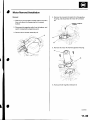
Motor Removal/lnstallation
Bemoval
1. Make sure you havethe anti-theftcode for the radio,
then write down the frequenciesfor the preset
buttons.
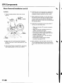
4. Removethe connectorbracket(A) onthegearbox
housing,and disconnectthe motor 2P connector
(B).
9.8 N.m {1.0kgf.m,
2. Disconnectthe negativecablefrom the battery,and
wait 3 minutesbefore beginningwork.
3. Removethe air cleanerassembly(A).
5. Removethe motor {A) from the gearboxhousing.
6. Removethe O-ring (B)and discardit.
(cont'd)
17-49
EPSComponents
(cont'dl
Motor RemovaUlnstallation
(
r 0 .Installthe motor on the gearboxby engagingthe
lnsiallation
7. Cleanthe mating surfaceof the motor (A) and
gearbox.
q
8 x '1.25
mm
20 N.m
12.0kgt.m,7.2lbl ftl
E
motor shaft and worm shaft (D).Note the motor
installationposition{directionof motor wires).
1 1 .Beforetighteningthe bolts,turn the motor two or
three times right and left about 45 degrees.lvlake
sure the motor is evenlyseatedon the steering
gearboxand that the O-ring is not pinchedbetlveen
the mating surfaces.
1 2 .Installthe removedDartsin the reverseorder of
removal.and note these items:
L==-
c].E@
Apply a thin coat of siliconegrease(P/N087338070E)tothe new O-ring(B),and carefullyfit it on
the motor.
9 . Apply grease{Nippon GreaseWR-S or equivalent
steeringgear grease)into the motor shaft (C).
17- 5 0
lvlakesure the motor 2P connectoris properly
connected.
lvlakesurethe motor and EPSwires are not
caughtor pinchedby any parts.
Reconnectthe negativecableto the battery.
D o t h e e n g i n ec o n t r o lm o d u l e( E C M )i d l e l e a r n
p r o c e d u r e( s e ep a g e1 1 - 1 3 9 ) .
Enterthe anti-theftcode for the radio station
Dresets.Resetthe clock,
Do the oower window control unit reset
procedure(seepage 22-1241.
1 3 .After installation,startthe engine,and let it idle.
Turn the steeringwheel from lock-to-lockseveral
times. Checkthat the EPSindicatordoes not come
on.
SteeringGearboxRemoval
Special Tool Required
Ball ioint remover,2Smm 0TlvlAC-S100200
8. Removethe cotter pin (A)from the tie-rod balljoint
nut {B),and loosenthe nut.
_t\
1. Raisethe front of vehicle,and make sure it is
securelysupponed.
2. Removethe front wheels.
R e m o v et h e d r i v e r ' sa i r b a g ( s e e p a g e 2 3 - 1 1 3 ) .
4 . Removethe steeringwheel (seepage 17-6).
5 . Removethe motor on the steeringgearbox (see
p a g el T - 4 9 ) .
6 . Removethe driver'sdashboardlower cover (see
page20-59)and under cover {seepage20-60).
7 . Removethe steeringjoint bolts (A),and disconnect
the steeringjoint by moving the steeringjoint (B)
toward the column.
l,a.:
'/
--L-
r0 mm HEXNUT
07MAC-S100200
9 . Separatethe tie-rod balljoint and damper steering
arm usingthe specialtool (seepage 18-10).Repeat
on the other side of the vehicle.
1 0 .G r a s pt h e r i g h ts i d et i e - r o d a, n d p u l lt h e r a c ka l l t h e
way to the passenger'sside,
1 1 . Removethe heat shield (A) mounting bolts from
the body stiffener,and let the heat shield lay
againstthe exhaust.
'
i
l
(cont'd)
17-51
EPSComponents
SteeringGearboxRemoval(cont'd)
12. Disconnect
the EPSwire harness6Pconnector
(A),
andremovethe EPSwire harness(B)andmountino
bracket(C).
1 4 . R e m o v et h e e n g i n ew i r e h a r n e s sc l a m p s{ A ) f r o m
the three mounting brackets.
-a--zi
i
F--_1
t5.
1 3 . Removethe groundcableterminal(A)fromthe
steeringgearboxhousing.
..(
.,/
a
bH \
ry T,-.lt'^ \
'"
_ - 1 . . 1 . - '
17-52
\--
Removethe heaterhose {B)from the bracket.
1 6 . Open the heatervalve cableclamp (A),and
disconnectthe heatervalve cable(B).Removethe
heatervalve (C)from the bulkhead,and move jt
aside.
I
17. Removethe bodv stiffener(A).
19. Removethe steeringstiffenerB from the right side
of the steeringgearbox.
i t1-:: .,
1 8 .Removelhe steeringstiffenerA from the left side
of the steeringgearbox.
20. Lower the steeringgearbox,and rotateit so the
pinion shaft points upward.
21. Removethe pinion shaft grommet (A)from the top
of the torque sensor.
(cont'd)
17-53
EPSComponents
SteeringGearboxRemoval{cont'd)
22. Move the steeringgearboxand tie-rod ends as an
assemblyto the wheelwellopening on the
passenger'sside.
23. Carefullyraisethe driver'sside (pinionside)ofthe
steeringgearbox(A) and tie-rod (B) until clearsthe
mastercylinderand under-hoodfuse relay box,
then removethe steeringgearbox.Be careful not to
damagethe hoses,linesand wtre narnesses.
17-51
SteeringGearboxOverhaul
ExplodedView
mm
I x '1.25
ftl
20 N.m(2.0kgf.m,7.2lbt
O.RING
Replace.
CONNECTOR
PINION
SHAFT
GROMMET
RACKGUIDE
-@
.
. DISCWASHEB @'--g
-sPRrNG
SCREW
L)-RACKGUIDE
6
' v---\
\.oc**u.
v
\ >-*\{i#r^i
--.
i
6^:,;
BOOT BAND
Beplace.
''
-'t
'"''/
s(./t' J
-l
.
GUIDE \
SLTDER
SRACKET
{^il
\J"
\
@
II
\
\
\
\
BOOTBAND
- Replace.
LOCKWASHER
Replace.
\
stot *,tttc
Renrace
\
LocK
'162 scREw
N.m
l t o . sr g f m , 1 1 9 l bfft )
Beqtace.
TIE.RODEND
rtE-ROD
54 N m {5.5kgf.m,40lbf ft)
44 N m {4.5 kgf.m, 33 tbt.ft)
(cont'd)
17-55
EPSComponents
SteeringGearboxOverhaul(cont'dl
Special Tools Required
. Locknutwrench 07ZAA-S5A0100
. Pincers,Oetiker1098or equivalent,commercially
available.
4. Removethe stop plate (A).the 12 mm flange bolts
(B),the O-rings(C),and the bracket(D)from the
sleeringgearbox.
NOTE:
. Referto the ExplodedView as neededduring this
procedure.
. Do not allow dust, dirt, or other foreign materialsto
enter into the steeringgearbox.
Eemoval
1, Removethe steeringgearbox(seepage 17-b1).
Disassembly
2. Unbendthe lock washer (A).
-,'i.
. Loosenthe locknut(A),then removethe rack guide
screw (B),sprlng (C),disc washer (D),and rack
g u i d e( E )f r o m t h e s t e e r i n gg e a r b o x .
- -.i::..:4,.-,
Holdthe bracket(A) with one wrencn, anq unscrew
both tie-rod ends (B)with anotherwrench. Remove
the lockwashers.
1 7-56
-
:.--. '
6. Removethe two boot bands (A)from boot (B).
Compressthe boot by hand,and apply vinyl tape
(C)so the boot ends stay collapsedand pulled back
8. Installthespecialtool (A) on the lock screw (B)
securely.then loosenand removethe lock screw
from the steeringgearboxhousing.
07zAA-S5A0r00
1 . Attachthe yoke (A) of a universalpullerto the
steeringgearboxmounts with bolts.Securely
clamp the yoke in a vise as shown. Do not clamp
the steeringgearboxhousingin the vise.
Removethe specialtool.
1 0 .Pull on the rackhousing(A)to remove it from the
steeringgearboxhousing,Removethe boot {B) and
s l i d e rg u i d e( C )f r o m t h e c y l i n d e r .
(cont'd)
17-57
EPSComponents
SteeringGearboxOverhaul(cont'd)
'll.
Checkthe slider guide for damageand cracks.
Using verniercalipersto measurethe thicknessof
the slider guide. lf the thicknessis lessthan service
l i m i t ,r e p l a c et h e s l i d e rg u i d e ,
-.---(fr--',
Il i l ( t t
f
Z,-----:-r-.--------.t.t'E-r
i @ r
25.3mm
{0.925in.}
12
,
/i\
,)))
15. Applymultipurpose
greaseto the indicated
part
part)
of
the
{shaded
outersurfaceof the rack
housing.Do not applyto the dentsandgrooves.
I
|
25.3 mm
{0.925in.l
Removeanddiscardthestopring{A)onthe
cylinderby expanding
it with snapringpliers.
Removeanddiscardthe lockscrew{B}.
\
13. Installthe new lock screw on the rack housing.
1 4 . I n s t a l l t h en e w s t o p r i n g i n t h e g r o o v e( C ) o nt h e
cylinderby expandingit with a snap ring pliers.Be
carefulnot to scratchor damagethe housing
surfacewith the stop ring edges.
I
17-58
16. Set the new boot bands (A) on the band installation
groovesof the boot (B) by aligningthe tabs (C)with
the holes (D)of the band.Do not closethe ear of the
boot band in this step.
1 1 . Compressthe boot by hand,and apply vinyl tape
(E)to the bellowsso the boot ends stay collapsed
and pulled back.
Passthe boot over the rack housingso the smaller
diameterend of the boot facesthe steering
gearboxhousing.
'19. Pushthe rack housing(A) into the steeringgearbox
housing(B) so the notch (C)is alignedwith the pin
(D)on the bottom of the gearboxhousinginside
20. Tightenthe lock screw {A) by hand first, then install
the specialtool (B)on the lock screw. Lightly
tighten the lock screw.Do not tighten the lock
screwto the specifiedtorque Yet.
1 8 .Attachthe yoke (A) of a universalpuller to the
gearboxhousingmounts with bolts.then securely
clamp the yoke in a vise as shown. Do not clamp
the steeringgearboxhousingin a vise.
21. Removethe specialtool.
(cont'd)
17-59
EPSComponents
SteeringGearboxOverhaul(cont'dl
22. Apply multipurposegreaseto the sliding surface
and circumferenceofthe rackguide (A),and install
it onto the gearboxhousing.Wipe the greaseoff
the threadedsectionofthe housrno.
'1
{
25. Centerthesteeringrackwithin its stroke,and align
t h e s l i d e rg u i d e( A ) w i t ht h e h o t e s( B )i n t h e b o o t ( C ) .
Fit the slider guide to the boot by pressingaround
the edgesof the holessecurely
- .- =-1,...'.
,. ,l
.j
2 3 . I n s t a l l t h ed i s cw a s h e r( B ) w i t hi t s c o n v e xs i d e
f a c i n gt h e r a c kg u i d e .I n s t a l l t h es p r i n g( C ) .A p p t y
sealantto the middle of the threadson the rack
guide screw (D),then installand tighten it to 25
N m (2.5kgf.m, 18 lbf.ft).Looselyinstatlrhetocknut
(E).
24. Apply multipurposegreaseto the sliding surfaceof
the slider guide (A).Keepgreaseoff of the rack-toslider guide mating surfacesand the boot-to-slider
guide mating surfaces.
Slidethe steeringrack all the way to left, and place
t h e s l i d e rg u i d eo n t h e s t e e r i n gr a c kb y a l i g n i n gt h e
bolt holes (B).
E
25 N.m 12.5kgt.m,18tbt.ft)
26. Beforeinstallingthe bracket(D),cleanthe mating
surfaceofthe 12 mm flange bolts (E)and the
bracket.Coatthe new O-rings{F)with multipurpose
g r e a s ea, n d i n s t a l l t h e mo n t h e ' 1 2m m f l a n g eb o l t s .
27. Looselyinstallthe bracketon the steeringrack by
tighteningthe 12 mm flange boltsto 25 N.m (2.5
kgf.m, 18lbf.ft).
28. Hold the gearboxhousingusing a yoke,then install
the specialtoolon the lock screw (A).Retightenthe
lock screwto the specifiedtorque values.
A
{ 1 6 . 5k g t . m , 1 1 9 l b f . f t }
29. Removethe specialtool.
17-60
30, Retightenthe 12 mm flange bolts (A) to the
soecifiedtoroue value.
3 4 . C l o s et h e e a r p o r t i o n( A )o f t h e b a n d s( B ) w i t h
, e t i k e r1 0 9 8o r
c o m m e r c i a l la
v v a i l a b l ep i n c e r sO
e q u i v a l e n(tC ) .
74 N.m (7.5kgf.m,5irlbf.ft)
5 t .
After tighteningthe 12 mm flange bolts, installa
new stop plate (B)over one of the bolt heads.Be
surethe tabs (C)of the stop plate are alignedwith
the flat surfacesof the bolt head.
32,
Cleanoff any greaseor contaminationfrom the
b o o t i n s t a l l a t i ognr o o v e so n t h e h o u s i n g .
Expandthe boot (A) by removingthe vinyltape,
and fit the boot ends (B) in the installationgrooves
o n t h e c y l i n d e rh o u s i n g .
3 5 . I n s t a l l t h en e w l o c kw a s h e r( A )w i t h i t s r a d i u s e d
side facing (B)the tie-rod (C),and screwthe tie-rod
on the bracket(D).Repeatthis stepfor the other
side of the tie-rod.Hold the bracketwith one
wrench,and tightenthe tie-rodsto the specified
torque with anotherwrench.
. .,,";=-.
, . ,
*=,,',
(cont'd)
17-61
EPSComponents
SteeringGearboxOverhaul(cont'dl
36. Bendthe lock washer againstthe flat spots on the
bracketwitha Iarge pair of pliers.
37. Adjust the rackguide screw {seepage 17-13).
17-62
SteeringGearboxInstallation
'1.
Beforeinstallingthe steeringgearbox,slidethe
rack all the way to the passenger'sside (right
direction).
4. Insertthe pinion shaft up through the bulkhead,
then slip the right side of the steeringgearbox
housing(A) over the mounting stud (C)on the
gearboxmounting bracket.
2 . Passthe right side of the steeringgearboxtogether
with the tie-rodsthrough the wheelwell openingon
the passenger'sside.Continuemoving the steering
gearboxtoward the passenger'sside untilthe
driver'sside tie-rodend and gearboxclearsthe
mastercylinderand under-hoodfuse Ielay box.
Lower the steeringgearbox.and move it toward
t h e d r i v e r ' ss i d eu n t i l t h es t e e r i n gg e a r b o xi s l n
Dosition.
\-
--'
'.'',
i
:-1
. . . .
Be carefulnot to damagethe hoses,lines
and wire harnesses.
10 x '1.25mm
61 N.m
{62 kgl m, 45 lb{ ftl
Installthe steeringstiffenerB, and lightlytighten
the steeringgearboxmounting nuts.
Installthe steeringstiffenerA with the gearbox
m o u n t i n gb o l t s .T h e nt i g h t e na l l t h e s t e e r i n g
gearboxmounting hardwareto the specifiedtorque.
1 0x 1 . 2 5m m
6l N.m
(6.2 kgt.m, 45 lbt.ft)
3 . I n s t a l l t h ep i n i o ns h a f tg r o m m e t( A ) .
.: --.-{
.
( c o n t ' d)
17-63
EPSComponents
SteeringGearboxInstallation(cont'd)
7. Installthebodystiffener(A),andtorquethe
mountingboltsto the specified
torque.
9. Reinstallthe heaterhose (A) on the hose bracket.
8 x 1.25mm
29 N.m {3.0kgf.m,22lbf.ftl
1 0 .Installthe enginewire harnessclamps (B)to the
three harnessbrackets.
L Installthe heatervalve (A) on the bulkhead,and
connectthe heatervalve cableend (B)to the heater
valve arm (C).Readjustthe heatervalve cable{see
page21-46).
L-t
:.i.t'
,
9.8N.m
(1.0kgf m,
7.2tbf.ftl
17-64
' It . Under
the steeringgearbox,installthe ground
cableterminal (A) on the steeringgearboxhousing.
9 . 8N . m
{1.0kgf.m,7.2lbf.ft)
12. lnstalltheEPSwire harnessbracket(A)on the
(B)
gearboxhousing,andconnectthe 6Pconnector
propefly.
9.8 N.m
{1.0kgt m,7.2 lbt.ftl
1 4 . Centerthe steeringrackwithin its stroke.
1 5 . Wipe off any greasecontaminationfrom lhe ball
joint taperedsectionand threads.Then reconnect
the tie-rod ends 1A)tothe damper steeringarms.
lnstallthe ball joint nut (B) and tighten them.
,-', ''l
:
1
)
B
10x 1.25mm
i€ N.m
{4.4 kgf.m.
32 tbt.ftl
1 3 . I n s t a l l t h eh e a ts h i e l d( A ) .
to.
,.!,..
''6
Installthe new cotter pins (C),and bend them as
shown.
f
(cont'd)
17-65
EPSComponents
4
SteeringGearboxInstallation(cont'dl
1 7 . Installthe motor on the steeringgearbox(seepage
17-49).
1 8 . lnstallthe steeringjoint (A).and reconnectthe
steeringshaft (B) and pinion shaft (C).Make sure
the steeringjoint is connectedas follows:
. I n s e r t t h eu p p e r e n do f t h e s t e e r i n gj o i n t o n t o t h e
steeringshaft (line up the bolt hole (D)with the
flat portion (E)on the shaft).
. Slip the lower end of the steeringjoint onto the
pinion shaft (line up the bolt hole with the groove
(F)around the shaft),and looselyinstallthe lower
joint bolt. Be sure that the lower joint bolt is
securelyin the groove in the pinion shaft.
. Pull on the steeringjoint to make surethat the
steeringjoint is fully seated.Then installthe
upper joint bolt, and tighten it to the specified
torque.Tightenthe lower joint bolt to the
specifiedtorque.
22. After installation,performthe following checks.
. Performthe front toe inspection.
. C h e c kt h e s t e e r i n gw h e e ls p o k e a n g l el.f s t e e r i n g
spokeanglesto the right and left are not equal
(steeringwheel and rackare not centered),
correctthe engagementof the joinvpinion shaft
serrations,then adjustthe front toe by turning
the tie-rods,if necessarv.
\
8 x '1.25mm
28 N.m
{2.9kgf.m,
21 tbt.ft)
1 9 .Installthedriver's dashboardlower cover (see
page 20-59)and under cover (seepage 20-60).
20. lf the steeringwheel was turned,centerthe cable
reel by first rotatingit clockwiseuntil it stops.Then
rotateit counterclockwise(abouttwo and half
turns) untilthe arrow mark on the label points
straightup. Reinstallthe steeringwheel (seepage
17-8).
)1
Installthe front wheels.
17-66
EPSControlUnit Removal/
Installation
Tie-rodBallJoint Boot Replacement
Special Tool Required
Attachment,42 mm 07OAD-P0A0100
1. Removethe passenger'sunder panel.
2. Turn up the floor carpel,removelhe EPScontrol
untr.
l. Removethe boot from the tie-rod end, and wipe the
old greaseoff the ball pin.
2 . P a c kt h e l o w e ra r e ao f t h e b a l l p i n ( A ) w i l h f r e s h
mulr purposegrease.
*-4
r/\-,
d______i.l+_D
-6rA
3 . Disconnectthe EPScontrol unit connectors.
lnstallthe EPScontrol unit in the reverseorder of
removal.
E
After installation,startthe engine,and let it idle.
Turn the steeringwheelfrom lock-to-lockseveral
times. Checkthat the EPSindicatordoes not come
on.
3. Packthe interiorof the new boot (B) and lip (C)with
fresh multipurposegrease.
Note these items when installingnew grease;
. Keepgreaseoffthe boot installationsection(D)
and the taperedsection(E)of the ball pin.
. Do not allow dust, dirt, or other foreign materials
to enterthe boot.
4. Installthe new boot (A) usingthe specialtool.The
boot must not have a gap at the boot installation
sections(B).After installingthe boot.checkthe ball
pin taperedsectionfor greasecontamination,and
wipe it if necessary.
07(lAD-P0A0100
17-67