1
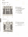
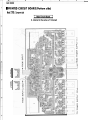
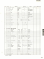
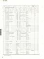
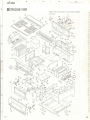
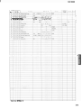
ERE0 POWER AMPLIFIER
f
IMPORTANT NOTICE
This manual has been provided for the use of authorized Yamaha Retailers and their service personnel.
I t has been assumed that basic service procedures inhennt to the industry, and more specifically Yamaha
Products, are already known and understcad by the users, and have therefore not been restated.
WARNING:
Failure to follow appropriate service and safety procedures when servicing this product
may result in personal injury, destruction of expensive Eamponentr and failure of the
product to perform as specified. For these reasons, we advise all Yamaha product ownel
rhat all sewib~required should be performed by an authorized Yamaha Retailer or th
appointed service representative.
IMPORTANT: The presentation or sale of this manual to any individual or firm does not ~onstitute
authorization, certification or remgnitidn of any appllcaMe technical aapabillties, or
establish a principle-agentrelationship o f any form.
The data provided is believed to be accurate and applicable to the unit(s) iddftxtted an the wver. The
research, engineering, and service departments of Yamaha are continually striving to imptwe Yamaha
products. Modifications are, therefore, inevitable and specificationsare subjectt~chaage wi&out notice or
obligation to retrofit. Should any discrepancy appear to exist, please contact the distributor's Servim
Division.
WARNING:
Static discharges can destroy expensive components. Discharge any staticelectricity your
body may have accumulated by grounding yourself to the ground buss in the unit (heavy
gauge black wires c~lncctto this buss).
IMPORTANT: Turn the unit OFF during d~sassemblyand parts replacement. Recheck all work before
you apply power to the unit.
L
- - -
CONTENTS
................. 1
................... 1
....................... 2
...................... 2
..................... 3
.............. 4
TO SERVICE PERSONNEL
FRONTIREAR PANELS
SPECIFICATIONS
BLOCK DIAGRAM
INTERNAL V I E W . .
DISASSEMBLY PROCEDURES
........................ 4
............. 5 9
.................. 10
........................... 11
ADJUSTMENTS
PRINTED CIRCUIT BOARD
SCHEMATIC DIAGRAM
WIRING..
PARTSLIST..
-
....................
12-20
YAMAHA CORPORATION
PO.Box1. Harnarnatsu.Japan
1.35K-604 liq@ Printed in Japan '88.8
I T 0 SERVICE P E R S O N N e '
1. Critical Componentr Information.
Components having special characteristics are marked A
and murt be replaced with parts having specifications equal
to those originally installed.
Meter impedance should be equivalent to 1500ohm shunted
by 0.151iF.
Leakage current murt not exceed 0.5mA.
Be sure to test for leakagewith the AC plug in bath polarities.
,
,
-
EQUIPMENT
+UNDER
TEST
2. Leakage Current Measurement (Far 12OV Model Only).
When service has been completed. it ir imperative that you
verify that all exposed conductive surfaces are properly
insulated from supply circuits.
WALL
OUTLET
INSULATING TABLE
AC LEAKAGE TESTER
JlvALENT
-
POLARIZATION
This amplifier product is equipped with a polarized alternating current line plug (a plug having one blade wider than the
other ).This plug will f i t into the power outlet only one way.
This ia a safety feature.
IFRONT/REAR PANELS
--
SPECIFICATIONS
Mlnlmum RMS Output P o w par Chnnrl
20Hz -20kHz
0.006% THO, 8S2
1 3 W + 130W
0.005% THD, 651
16(IW+lSMN
18OW+180W
0.01% THD, 4 n
Dynamic Pomr per Channel
(by IHF Dqnmlc Hredrmom mesrurinOmethod)
8&2
180W
6n
24w
4n
34ow
zn
49w
m w
~n
Pomr Eand Width
O M % THD, 65W. 8 0
1OHz -100kHr
Dmpinq Factor
1kHz, 8 n
loo0
I w u t San$itiuihl/lmpedama
MAIN IN 130W,8&2
12mV120kn
Fm(uncy R.rpons
20Hz -2OkHz. MAIN IN
+O, -0.3dB
Total Harmonic DMonion IZOHz -ZOkHz)
MAIN IN TO SP OUT, 1 3 0 ~8, n
0.005%
S i i l t o Noise Ratio (IHF-A-Nwork)
MAIN IN (Shorted)
126dB
R r i d u J Noise (IHF-A-Network)
15@V
Chonlrl Sopantion
IkHz, Input Shorted, Vol. max.
96d6
Powor SUPMY
ACIMV, WHz
Powa Consumption
880W
AC OvNR
Un Sw~tchedx 1
WOW max.
D i m w l o n (W x H x D)
473 x 170 x 469mm
1185/8"x6-11/16
x 187/16"l
WaIglu
28kg I61 lbs 11 or)
_1
DIMENSION
-io
.
-
-
o :
-?!
3
-'P
Unit: mm (inch)
*~mot~om
n : u b b t m d m m without notice.
IUI
ICI
.-... U.S.A. Modal
D W m hl&
B L O C K DIAGRAM
P101,103.ID5.107
INPUT
SP
A N m
P W LEVa METER
PrnTECTlON
*=
M L T H ALP
0%-Zm
D301.302
UNSWITCHEO
otr
.INTERNAL
VIEW
TOP VlEW
0 ELECTRICAL CAPACITOR:
22000pF 80V x 2
OINPUTCIRCUIT BOARD:
VOLTAGE AMP SECTION 81DIRECT
ERROR CORRECTION SECTION
@MAIN CIRCUITBOARD (Lch):
H.C.A. POWER STAGE
@POWER TRANSFORMER
U model : XE669001
C model : XE670001
@MAIN CIRCUIT BOARD (Rch):
H.C.A. POWER STAGE
BOTTOM VlEW
@POWERSUPPLY CIRCUIT BOARD (2):
OUTPUT COIL 81OUTPUT ERROR
P O W E R SUPPLY CIRCUIT BOARD (11:
POWER SUPPLY SECTION
(* B1.f BZandiB3)
&PROTECTION CIRCUITSECTION
@METER CIRCUIT BOARD (1)
DISASSEMBLY PROCEDURES
-
(Remove parts in disassembly order as numbered.)
1. Removal of Top Cover Ass'y
Remove 11 screws ( @ ) in Fig. 1.
2. Removal of Bottom Cover
Remove 24 screws ( @ ) in Fig. 1.
3. Removal of Wood Panel Ass'y
Remove 8 screws ( @ ) in Fig. 1.
4. Removal of Front Panel
Remove 4 screws ( @ ) and plastic rivet ( @ ) in
Fig. 1.
--
8
Q
Fig. 1
-
ADJUSTMENTS
Idling Adjustment
1) Remove the wood panel assembly.
2) Adjust VR201 (both L and R) so that the voltage
between t e s t pins TP1 and TP2 in the main circuit
board becomes DCGOmV + 590mV.
,
. -.--
1
I
TPl
.
lvlerer Circuit Board
Main Circuit Board
VR201
Meter A d justment
~
1 ) Connect a 8.9 dummy load.
,. . ,.
,.
2) Aalusr v n r u d IL ch) and VR404 (R ch) so that
meter indicator reads OW with no signal applied.
3) Apply 1kHz sine wave signal to INPUT and set the
signal level so that 28.3Vrms voltage is obtained at
both ends of the dummy load.
4) Adjust VR401 (L ch) and VR402 (R ch) so that the
meter indicator reads 1OOW.
5) Recheck t hat the meter indicator reads OW with no
signal applied and adjiust again if necessary.
TP2
=
.PRINTED
Note)
CIRCUIT B O A R D (Pattern side)
ZTEi : Component ride
I
Main Circuit Board
1
(L channel is the same as R channel)
FROM :POWER SUPPLY II )
TO : POWER SUPPLY
( I)
TO :POWER SUPPLY ( I )
a
T O :POWER SUPPLY (2
.:
FROM : POWER SUPPLY (1 1
%WER SUPPLY (1 1
METER Lch
J
ER SUPPLY (31
L
PROTECTION
POWER SPEAKERS OFF
FR0M:PQWER SUPPLY (1)-
Meter Circuit Board (2)
-
C
L
A
6
C
D
IW-1000
l
PRINTED CIRCUIT BOARD(Pattern side)
1
Notal ZTES : Component side
FROM : POWER
SU
Meter Circuit Board
I Power Supply Circuit Board (3)1
-
FROM :METER ( I )
2
-
5
-
-
4
Opention Check of Input Circuit Bbafd Alone
Connect IN and E of board-in going to R channel
main circuit board of the input circuit board and IN
and E of board-in going to L channel one to sockets
R, RE, LE and L which receive board-in of the power
circuit board (2) with wires.
Connect i a O V power source to +82, E and -82 of
board-in going to the power supply circuit board L1 I
and then wnnect EM terminal to -82 with 47k.Q.
resistance included.
I
TO : MAIN
Input Circuit Board
1
,,..
-.
!
R 13%
C
0
K
A
5
A
6
9
m-20a0
WIRING
150mA 8 V x 6
METER (II
POWER SUPPLY ( 1 )
POWER SUPPLY (2)
-2000
=WARNING
LIST
I
ELECTRICAL PARTS
E
E
XNew Parts
(%%%a)
NR
Components having special characteristicsare marked
and must be replaced
with Parts having specificationsequal to those originally installed.
*Carbon resistors Il/BW or 1/4W) are not included in the ELECT
PARTS list. For the parts No. of the carbon resistor, refer to p. 20.
*New Parts
(%I&$&)
NR
%New Parts
(M%BI$)
NR
i
I
L
*
i
L
i N s w Parts
(RfLlbb) NR
IMECHANI S M PARTS
NO-, 9 : Diameter
IEXPLODED VIEW
Tighten this scraw.securely as it grounds the circuit
the chartis.
\
k,..
I
1
Part No.
41
1 Fi
42
/
38 j 41 jOO(Ceramic Cap.
CB i 60 i 08
i
1
10 Cover
%!New Parts (%R%&)NR
0.0lpF
t
5
2
i
Parts List for Carbon Resistor