1
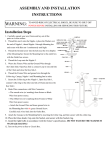
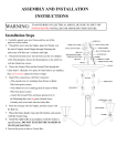
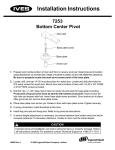
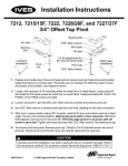
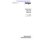
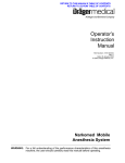
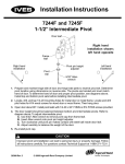
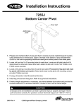
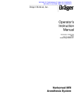
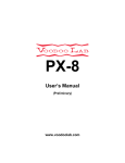
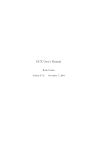
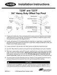
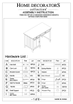
Installation Guide
Dräger Narkomed 6000 Mounting Channel(s) Installation
The purpose of this guide is to:
1.
2.
3.
4.
Describe attachment of the GCX Top Shelf Base Plate with 28" Channel (NAD P/N: 4116581).
Describe attachment of the GCX Top Shelf Base Plate with Philips Camlock Rails (NAD P/N: 4116585).
Describe attachment of the GCX 20.25" Left Side Channel (NAD P/N: 4116582).
Describe attachment of the 44" Right Side Channel with Adapter (NAD P/N: 4116584).
Top Shelf Base Plate with 28" Channel (NAD P/N: 4116581)
1. Find the threaded inserts by locating the two (2) or four (4) dimples in the top of the anesthesia machine. If you have
difficulty finding these dimples, use the top shelf base plate provided as a template, and mark the top of the machine in
the locations indicated.
2. Drill in the locations marked in step #1 (only where dimples are present), using a ¼” diameter drill bit. Drill bit should
not penetrate material more than ¼”. Drilling too deeply will damage insert threads and internal components of the
machine. Remove all drilling chips.
3. Run the (2) or (4) #10-32 x 1" PHMS screws through the top plate and into the holes drilled in step #2.
4. Attach the Tip Warning Label (Figure 1) to the front-center of the blue top shelf bezel.
Figure 1
Location of threaded
inserts for 2-hole
NM6000 Top Shelf
Top Shelf Base Plate
with 28" Channel
secured using 2 or 4
#10-32 x 1" PHMS
Location of threaded
inserts for 4-hole
NM6000 Top Shelf
Tip Warning
Label Location
Top Shelf Base Plate with Philips Camlock Rails (NAD P/N: 4116585)
1. Follow Steps 1 - 4 in the above section.
2. Top Shelf Base Plate and Camlock Rails to be mounted only in orientation shown in pictures below.
DU-DR-0013-DM Rev B 7/20/00 Page 1 of 2
20.25" Left Side Channel (NAD P/N: 411652)
1. There are two mounting hole cover plates on the left side of the upper portion of the NM6000 (only one if Hose
Management Boom Arm is present). To remove the upper mounting hole cover plate, remove the top access door by
loosening thumb screw and pulling door down (if Integrated Patient Monitoring Module is present refer to Dräger
Medical Service Manual for removal and reinstallation). With a 3/8" hex nut driver, remove the 2 nuts holding the
mounting hole cover plate and set plate aside. Replace and secure top access door, if present or module per
Service Manual. To remove the lower mounting hole cover plate, remove the Gas Analyzer Pod by loosening thumb
screw. Exercise caution when pulling the Pod as a 1/8" hose and cable with 25 pin D connector are attached. The
hose and connector must be disconnected from the Pod to proceed - HANDLE WITH CARE! With a 3/8" hex nut
driver, remove the 2 nuts holding the mounting hole cover plate and set plate aside. To remove and replace Gas
Analyzer Pod, refer to Section 4.23 of the current edition of Service Information CD Subscription, Dräger Medical
P/N 4114417(-001, -002, -003, -004) (A printed service manual is available, Dräger Medical P/N 4112817-012) for
installing and testing the Pod before returning to service.
2. If Hose Management Boom Arm is present in upper holes, remove and remount with Dräger Boom Arm Adapter
Kit, Dräger Medical P/N 4116586.
3. Attach the Channel using the supplied (4) ¼-20 x ¾” FHMS.
4. Attach the Tip Warning Label (reference figure 1) to the blue top shelf bezel just above the channel.
Tip Warning
Label Location
(Ref. Figure 1)
Top Access
Door
¼-20
Inserts
20.25" Channel
secured with
(4) ¼-20 x ¾” FHMS
Mounting Hole
Cover Plates
Bottom Access
(Gas Analyzer Pod)
44" Right Side Channel with Adapter (NAD P/N: 4116584)
1. The Mounting Channel attaches to the NM6000 using threaded inserts on the right side panel. Determine if the right
side panel has the threaded inserts. February 2000 and later machines have the appropriate threaded inserts.
Any machines manufactured previously could require the right side panel kit to be ordered from Dräger Medical
(P/N: 4114788). Remove (2) two screws on front edge, (6) six screws on back edge then tilt back edge away from
machine and slide front edge forward to remove panel. Note: Top front edge screw may hold a spacer for alignment
of panel with top shelf. Reverse procedure to install new panel.
2. Remove Hole Plug Caps (if necessary), and attach the right side Mounting Channel with Adapter using the supplied
#8-32 x 3/8" PHMS-SEMS (10).
3. Attach Tip Warning Label (reference figure 1) to the upper-rear section of the right side panel.
Tip Warning Label Location
(Ref. Figure 1)
NM6000 Right Side Panel
Mounting Channel with Adapter
#8-32 (10) Threaded Inserts
(Remove Caps, if necessary)
#8-32 x 3/8" PHMS-SEMS (10)
DU-DR-0013-DM Rev B 7/20/00 Page 2 of 2