1
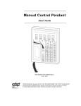
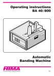
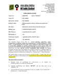
VHS MECHANICAL ADJUSTMENT MANUAL VII TS-10 MECHANISM Please use this manual with the service manual. MECHANISM DECK 1. TABLE OF CONTENTS Disassembly and Reassembly 1-1 1-1-1 1-1-2 1-2 1-2-1 1-2-2 1-2-4 1-2-3 1-2-5 1-2-6 1-2-7 1-2-8 Deck Parts Locations ........................................................... 3 Top View ............................................................................. 3 Bottom View ....................................................................... 5 Main Deck ........................................................................... 6 Lever FL Door Removal ..................................................... 6 Holder FL Cassette Ass’y Removal .................................... 6 Lever FL Arm Ass’y Removal ............................................ 7 Slider FL Drive, Gear FL Cam Removal ............................ 7 Gear Worm Wheel Removal ............................................... 8 Motor Loading Ass’y Removal ........................................... 8 Bracket Gear, Gear Joint 2, 1 Removal ............................... 9 Gear Loading Drive, Slider Cam, Lever Load S, T Ass’y Removal ................................................................. 9 1-2-9 Gear Loading Drive, Slider Cam, Lever Load S, T Ass’y Assembly ............................................................. 10 1-2-10 Lever Pinch Drive, Lever Tension Drive Removal ........... 10 1-2-11 Lever Tension Ass’y, Band Brake Ass’y Removal ........... 11 1-2-12 Lever Brake S, T Ass’y Removal ...................................... 11 1-2-13 Gear Idle Ass’y Removal .................................................. 12 1-2-14 Disk S, T Reel Removal .................................................... 12 1-2-15 Holder Clutch Ass’y Removal ........................................... 13 1-2-16 Lever Up Down Ass’y, Gear Center Ass’y Removal ........ 13 1-2-18 Lever Unit Pinch Ass’y, Plate Joint, Spring Pinch Drive Removal ............................................. 14 1-2-17 Guide Cassette Door Removal .......................................... 14 1-2-19 Lever #9 Guide Ass’y Removal ........................................ 15 1-2-20 FE Head Removal .............................................................. 15 1-2-21 ACE Head Removal .......................................................... 16 1-2-22 Slider S, T Ass’y Removal ................................................ 16 1-2-23 Plate Ground Deck, Cylinder Ass’y Removal ................... 17 1-2-24 Belt Pulley Removal .......................................................... 17 1-2-26 Damper Capstan, Motor Capstan Ass’y Removal ............. 18 1-2-27 How to Eject the Cassette Tape ......................................... 18 1-3 The table of clearing, Lubrication and replacement time about principal parts .............................. 19 1-4 Tools and fixtures reguired for service................................20 2. Alignment and Adjustment 2-1 2-2 2-2-1 2-2-2 2-2-3 2-2-4 2-2-5 2-3 Tape Transport System and Adjustment Locations ........... 21 Tape Transport System Adjustment .................................. 22 ACE Head Assembly Adjustment ..................................... 22 Linearity Adjustment (Guide roller S, T adjustment) ..... 23 Check Transitional Operation from RPS to Play ............. 24 Envelope Check ................................................................. 24 Tape Wrinkle Check .......................................................... 24 Reel Torque ....................................................................... 24 –2 – 1. Disassembly and Reassembly 1-1 Deck Parts Locations 1-1-1 Top View Œ ˇ ¨ ˆ Fig. 1-1 Top parts Location-1 Œ ´ ˇ ¨ ˆ Ø GEAR FL CAM MOTOR LOADING ASS’Y LEVER FL ARM ASS’Y HOLDER FL CASSETTE ASS’Y LEVER FL DOOR SLIDER FL DRIVE –3 – Ø ´ ´ Œ Ø ∏ ” ˇ ’” Ô ˝ ¨ ˆ Ò Fig. 1-2 Top Parts Location-2 Œ ´ ˇ ¨ ˆ Ø ∏ FE HEAD CYLINDER ASS’Y ACE HEAD ASS’Y LEVER UNIT PINCH ASS’Y LEVER #9 GUIDE ASS’Y LEVER TENSION ASS’Y BAND BRAKE ASS’Y ” ’ ˝ Ô Ò –4 – DISK S REEL LEVER S BRAKE ASS’Y GEAR IDLE LEVER IDLE LEVER T BRAKE ASS’Y DISK T REEL 1-1-2 Bottom View Œ ´ ¨ ˇ ” ’ ˆ Ø ˝ Fig. 1-3 Bottom Parts Location Œ ´ ˇ ¨ ˆ Ø ∏ ” ’ ˝ GEAR JOINT 1 GEAR JOINT 2 BRACKET GEAR MOTOR CAPSTAN ASS’Y LEVER T LOAD ASS’Y GEAR LOADING DRIVE LEVER S LOAD ASS’Y HOLDER CLUTCH ASS’Y BELT PULLEY SLIDER CAM –5 – ∏ 1-2 Main Deck 1-2-1 Lever FL Door Removal 1-2-2 Holder FL Cassette Ass’y Removal 1) Push the Holder FL Cassette Ass'y Œ about 20mm in the direction of arrow “A”. 2) Rotate the Lever FL Door ´ in the direction of arrow “B”. 3) Release the Hook ˇ and Remove the Lever FL Door ´ in the direction of arrow “C”. 1) Pull the Holder FL Cassette Ass'y Œ to the eject position. 2) Pull the Holder FL Cassette Ass'y Œ as grasping the Holder FL Cassette Ass'y Œ and Lever FL Cassette-R ´ in the same time to release hooking from Main Base until the Boss [A] of Holder FL Cassette Ass'y Œ is taken out from the Rail [B]. 3) Lift the Holder FL Cassette Ass'y Œ, in this time, you have to grasp the Lever FL Cassette-R ´ Continuously until the Holder FL Cassette Ass'y Œ is taken out completely. Œ HOLDER FL CASSETTE ASS'Y "A" Note : Be sure to insert Lever FL Cassette-R ´ in the direction of “A” to prevent separation and breakage of the Lever FL Cassette-R ´ at disassembling and reassembling. "B" ´ LEVER FL DOOR ˇ HOOK "C" Fig. 1-4 Lever FL Door Removal RAIL [B] Œ HOLDER FL CASSETTEE ASS`Y "A" ´ LEVER FL CASSETTEE -R BOSS [A] Fig. 1-5 Holder FL Cassette Ass’y Removal –6 – 1-2-3 Slider FL Drive, Gear FL Cam Removal 1-2-4 Lever FL Arm Ass’y Removal 1) Pull the Slider FL Drive Œ to the front direction. 2) Remove the Slider FL Drive Œ in the direction of arrow. (Refer to Fig. 1-6) 3) Remove the Gear FL cam ´. 1) Push the hole “A” in the direction of arrow “B” use the pin.(about Dia.2.5) 2) Pull out the Lever FL Arm Ass'y Œ from the Boss of Main Base. 3) Remove the Lever FL Arm Ass'y Œ in the direction of arrow “C”. Note : When reinstalling be sure to reassemble Slider FL drive Œ after you insert the Boss of Lever FL ARM-R in Groove of Slider Fl drive Œ. HOLE "A" Assembly : Align the Gear FL Cam Œ with the Gear worm wheel Post as shown drawing. (Refer to Timing point) PIN "B" "C" Œ LEVER FL ARM ASS`Y Fig. 1-8 Lever FL Arm Ass’y Removal ´ GEAR FL CAM Œ SLIDER FL DRIVE Fig. 1-6 Slider FL Drive Removal Œ GEAR FL CAM GEAR WORM WHEEL POST TIMING POINT Fig. 1-7 Gear FL Cam, Gear Worm –7 – 1-2-5 Gear Worm Wheel Removal 1-2-6 Motor Loading Ass’y Removal 1) Remove the Gear Worm wheel Œ. 1) Remove the screw Œ. 2) Remove the Motor Loading Ass’y ´. ´ MOTOR LOADING ASS`Y Œ SCREW Œ GEAR WORM WHEEL Fig. 1-10 Motor Loading Ass’y Removal Fig. 1-9 Gear Worm Wheel Removal –8 – 1-2-7 Bracket Gear, Gear Joint 2, 1 Removal 1) Remove the SCREW Œ. 2) Remove the Bracket Gear ´. 3) Remove the Gear Joint 2 ˇ. 4) Remove the Gear Joint 1 ¨. Assembly : 1) Be sure to align dot mark of Gear Joint 1 Œ with dot mark of Gear Joint 2 ´ as shown Fig 1-12. (Refer to Timing point1) 2) Confirm the Timing Point 2 of the Gear Joint 2 ´ and Slider Cam ˇ. 1-2-8 Gear Loading Drive, Slider Cam, Lever Load S, T Ass’y Removal 1) Remove the Belt Pulley. (Refer to Fig. 1-30) 2) Remove the Gear Loading Drive Œ after releasing Hook [A] in the direction arrow as shown in detail drawing. 3) Remove the Slider Cam ´. 4) Remove the Lever Load S ˇ, Link Load S ˆ & Lever Load T ¨, Link Load T Ø. HOOK(A) ¨ GEAR JOINT 1 ´ SLIDE CAM ˇ GEAR JOINT 2 Œ SCREW Œ GEAR LOADING DRIVE ¨ LEVER LOAD T Ø LINK LOAD T ´ BRAKET GEAR ˇ LEVER LOAD S ˆ LINK LOAD S Fig. 1-11 Bracket Gear, Gear Joint 1,2 Removal Fig. 1-13 Gear Loading Drive, Slider Cam, Lever T, S Load Ass’y Removal Œ GEAR JOINT1 ´ GEAR JOINT2 ˇ SLIDER CAM TIMING POINT 1 TIMING POINT 2 Fig. 1-12 Gear Joint 1,2 Assembly –9 – 1-2-9 Gear Loading Drive, Slider Cam, Lever Load S, T Ass’y Assembly 1-2-10 Lever Pinch Drive, Lever Tension Drive Removal 1) When reinstalling, be sure to align dot of Lever Load T Ass'y Œ with dot of Lever Load S Ass'y ´ as shown in drawing, (Refer to Timing Point 1). 2) Insert the Pin A,B,C,D into the Slider Cam ˇ hole, 3) Be sure to align dot of Lever Load T Œ and dot of Gear Loading Drive ¨, (Refer to Timing Point 2). 4) Aline dot of Gear Loading drive ¨ with mark of Slider Cam ˇ as shown in drawing(Refer to Timing Point 3). 1) Remove the Lever Pinch Drive Œ, Lever Tension Drive ´. Œ LEVER PINCH DRIVE ´ LEVER TENSION DRIVE TIMING POINT 1 Œ LEVER LOAD T ´ LEVER LOAD S LEVER LOAD T Fig. 1-15 Lever Pinch Drive, Lever Tension Drive Removal LEVER LOAD S TIMING POINT 2 TIMING POINT 3 PIN A PIN C PIN D PIN B ˇ SLIDER CAM Fig. 1-14 Gear Loading Drive, Slider Cam, Lever Load S, T Ass’y Assembly – 10 – 1-2-11 Lever Tension Ass’y, Band Brake Ass’y Removal 1-2-12 Lever Brake S, T Ass’y Removal 1) Remove the Lever Brake S Ass'y (Refer to Fig 1-17). 2) Remove the Spring Tension Lever Œ. 3) Rotate stopper of Main Base in the direction of arrow “A”. 4) Lift the Lever Tension Ass'y ´ & Band brake Ass'y ˇ. Note : 1) When replacing the Lever Tension Ass'y ´, be sure to apply Grease on the post, 2) Take care not to touch stain on the felt side, and not to be folder and broken Band brake Ass'y 3) After Lever Tension Ass'y seated, Rotate stopper of Main Base to the Mark[B]. 1) Release the Hook [A] and the Hook [B], [C] in the direction of arrow as shown in Fig 1-17. 2) Lift the Lever S, T Brake Ass'y Œ, ´ with spring brake ˇ. Assembly : 1)Assembly the Lever S Brake Ass'y Œ on the Main Base. 2)Assembly the Lever T Brake Ass'y ´ with spring brake ˇ. Note : Take extreme care not to be folded and transformed Spring Brake at removing or reinstalling. ˇ BAND BRAKE ASS`Y HOOK(A) ´ LEVER TENTION ASS`Y ˇ SPRING BRAKE Œ SPRING TENTION LEVER STOPPER "A" MARK[B] Œ LEVER S BRAKE ASS`Y HOOK(C) HOOK(B) ´ LEVER T BRAKE ASS`Y Fig. 1-16 Lever Tension Ass’y, Band Brake Ass’y Removal Fig. 1-17 Lever Brake S, T Ass’y Removal – 11 – 1-2-13 Gear Idle Ass’y Removal 1-2-14 Disk S, T Reel Removal 1) Push the Lever Idle Œ in the direction of arrow “A”, “B”. 2) Lift the Lever Idle Œ. 1) Lift the Disk S, T Reel Œ, ´. Œ DISK S REEL Assembly : 1) Apply oil in two Bosses of Lever Idle Œ. 2) Assemble the Gear Idle ´ with the Lever Idle Œ. Note : When replacing the Gear Idle ´, be sure to add oil in the boss of Lever Idle Œ. ´ DISK T REEL "A" Œ LEVER IDLE ´ GEAR IDLE "B" ´ GEAR IDLE HOOK "C" Fig. 1-19 Disk S, T Reel Removal Fig. 1-18 Gear Idle Ass’y Removal – 12 – 1-2-15 Holder Clutch Ass’y Removal 1-2-16 Lever Up Down Ass’y, Gear Center Ass’y Removal 1) Remove the Washer Slit Œ. 2) Lift the Holder Clutch Ass’y ´. Note : When you reinstall Holder Clutch Ass'y 1) Check the condition of spring as shown in detail A. 2) Don't push Holder Clutch Ass'y down with excessive force Just insert Holder Clutch Ass'y into post center with dead force and Rotate it smoothly. Be sure to confirm that spring is in the slit of Gear Center Ass'y as shown in detail B. Œ WASHER SLIT ´ HOLDER CLUTCH ASS`Y 1) Remove the 2 hooks in the direction of arrow as shown Fig. 1-21 and lift the Lever Up Down Ass’y Œ. 2) Lift the Gear Center Ass’y ´. Assembly : 1) Insert the Lever Up Down Ass'y Œ in the rectangular holes on Main Base as shown in Fig 1-22. 2) Lift the Lever Up Down Ass'y Œ about 35 degree.(Refer to Fig 1-22) 3) Insert Ring of the Gear Center Ass'y ´ in the Guide of the Lever Up Down Ass'y Œ. 4) Insert the Gear Center Ass'y ´ in the post on Main Base. 5) Push down the Lever Up Down Ass'y Œ for locking of the Hook. Note : 1) Take care not to separate and sentence does not mark sense. 2) Be sure to confirm that Ring of the Gear Center Ass'y ´ is in the Guide of the Lever Up Down Ass'y Œ after finishing assembly of Lever Up Œ LEVER UP DOWN ASS`Y ´ GEAR CENTER ASS`Y DETAIL A <BAD> SPRING <GOOD> DETAIL B Fig. 1-21 Lever Up Down Ass’y Removal SPRING GEAR CENTER ASS'Y GUIDE LEVER UP DOWN ASS'Y <BAD> RING <GOOD> GEAR POST HOOK 35 Fig. 1-20 Holder Clutch Ass’y Removal MAIN BASE Fig. 1-22 Lever Up Down Ass’y Removal – 13 – 1-2-17 Guide Cassette Door Removal 1) Lift the Hook [A]. 2) Rotate the Guide Cassette Door Œ in the direction of arrow. Note : After reinstalling the Guide Cassette Door Œ sure the Hook [A]. Œ GUIDE CASSETTE DOOR 1-2-18 Lever Unit Pinch Ass’y, Plate Joint, Spring Pinch Drive Removal 1) Lift the Unit Pinch Ass’y Œ. 2) Remove the Plate Joint ´ from Lever Pinch Drive. 3) Remove the Spring Pinch Drive ˇ. Note : 1) Take extreme care not to touch the grease on the Roller Pinch. 2) When reinstalling, be sure to apply grease on the post pinch roller. Œ LEVER UNIT PINCH ASS`Y HOOK [A] ´ PLATE JOINT ˇ SPRING PINCH DRIVE Fig. 1-23 Guide Cassette Door Removal Fig. 1-24 Lever Unit Pinch Ass’y, Plate Joint, Spring Pinch Drive Removal – 14 – 1-2-19 Lever #9 Guide Ass’y Removal 1-2-20 FE Head Removal 1) Remove the Spring #9 Guide Œ. 2) Lift the Spring #9 Guide Ass’y ´ in the direction of arrow “A”. 1) Remove the screw Œ. 2) Lift the FE Head ´. Note : 1) Take extreme care not to get grease on the tape Guide Post. 2) After reinstalling, check the bottom side of the Post #9 Guide to the top side of Main Base. Œ FE HEAD "A" Œ SPRING #9 GUIDE ´ LEVER #9 GUIDE ASS`Y "B" Fig. 1-26 FE Head Removal Fig. 1-25 Lever #9 Guide Ass’y Removal – 15 – 1-2-21 ACE Head Removal 1-2-22 Slider S, T Ass’y Removal 1) Pull out the FPC from connector of ACE Head Ass’y ´. 2) Remove the screw Œ. 3) Lift the ACE Head Ass’y ´. 1) Move the Slider S, T Ass’y Œ, ´ to slot, and then lift it to remove. (Refer to arrow) Œ SLIDER S ASS`Y Œ SCREW ´ SLIDER T ASS`Y ´ HEAD ACE ASS`Y Fig. 1-28 Slider S, T Ass’y Removal Fig. 1-27 ACE Head Removal – 16 – 1-2-23 Plate Ground Deck, Cylinder Ass’y Removal 1-2-24 Belt Pulley Removal 1) Remove the 3 Screws Œ. 2) Lift the Plate Ground Deck ´. 3) Lift the Cylinder Ass’y ˇ. 1) Remove the Belt Pulley Œ. Note : Take extreme care not to get grease on Belt Pulley Œ at assembling or reassembling. Assembly : 1) Match the 3 holes in the bottom of Cylinder ass'y ˇ to the 3 holes of Main Base as attending not to drop or knock the Cylinder ass'y ˇ. 2) Tighten the 1 Screw Œ. 3) Match the Plate Ground Deck ´ to the Hole of Base Main. 4) Tighten the other 2 Screws Œ. Œ BELT PULLEY Note : 1) Take care not to touch the Cylinder Ass'y ˇ and the tape guide post at reinstalling. 2) When reinstalling, Don't push down too much on Screw Driver. Œ 3 SCREWS Fig. 1-30 Belt Pulley Removal ´ PLATE GROUND DECK 1-2-25 Level Head Cleaner Ass’y Removal 1) Release the Hook Œ. 2) Lift the Lever Head Cleaner Ass’y ´. ´ LEVER HEAD CLEANER ASS'Y Œ HOOK SLEEVE-HEAD CLEANER ˇ CYLINDER ASS'Y Fig. 1-31 Level Head Cleaner Ass’y Removal Fig. 1-29 Plate Ground Deck, Cylinder Ass’y Removal – 17 – 1-2-26 Damper Capstan, Motor Capstan Ass’y Removal 1) Remove the Damper Capstan Œ in the direction of arrow. 2) Remove the 3 Screws ´. 3) Remove the Motor Capstan Ass’y ˇ. 1-2-27 How to Eject the Cassette Tape (If the unit does not operate on condition that is inserted into housing ass’y) 1) Turn the Gear worm Œ clockwise with screw driver. (Refer to arrow) (Other method : Remove the Screw of Motor Load Ass'y, Separate the Motor Load Ass'y) Assembly : 1) Match the 3 holes of Motor Capstan Ass’y ˇ to the 3 holes of Main Base. Be careful not to drop or knock the Motor Capstan Ass'y ˇ. 2) Tighten the 3 Screws ´ in the direction of arrow as shown detail drawing. 3) Assemble the Damper Capstan Œ. Œ GEAR WORM Note : After tightening screws, check if there is gap between the head of screws and the top side of Main Base. There should have no gap between the head of screws and the top side of Main Base. After reinstalling, adjusting the tape transport system again. ´ 3 SCREWS A B Fig. 1-33 C Œ DAMPER CAPSTAN 2) When Slider S,T are approched in the position of unloading, rotate holder Clutch counterclockwise after inserting screw driver in the hole of frame's bottom in order to wind the unwinded tape. (Refer to Fig.1-34) (If you rotate Gear Worm Œ continuously when tape is in state of unwinding, you may cause a tape contamination by grease and tape damage. Be sure to wind the unwinded tape in the state of set horizently.) 3) Rotate Gear Worm Œ clockwise using screw driver again up to the state of eject mode and then pick out the tape.(Refer to Fig.1-33) ˇ MOTOR CAPSTAN ASS'Y Fig. 1-32 Damper Capstan,Motor Capstan Ass’y Removal FRAME Fig. 1-34 – 18 – 1-3 The table of clearing, Lubrication and replacement time about principal parts 1) The replacement time of parts is not life of parts. 2) The table 1-1 is that the VCR Set is in normal condition (normal temperature, normal humidity). The checking period may be changed owing to the condition of use, runtime and environmental conditions. 3) Life of the Cylinder Ass’y is depend on the condition of use. 4) See exploded view for location of each parts. <Table 1-1> * T A P E P A T H S Y S T E M D R I V I N G S Y S T E M B R A K E S Y S T E M Parts Name POST TENSION SLANT POST S, T #8 GUIDE SHAFT CAPSTAN SHAFT #9 GUIDE POST #3 GUIDE POST GUIDE ROLLER S, T CYLINDER ASS’Y FE HEAD ACE HEAD PINCH ROLLER POST REEL S, T SLEEVE TENSION POST CENTER LEVER IDLE BOSS (2Point) CAPSTAN MOTOR PULLEY BELT PULLEY HOLDER CLUTCH ASS’Y Checking Period 500 1000 1500 2000 2500 3000 3500 4000 4500 5000 ∆ ∆ ∆ ∆ ∆ ∆ ∆ ∆ ∆ ∆ ∆ ∆ ∆ ∆ ∆ ∆ ∆ ∆ O ∆ O O ◆ ◆ ◆ ◆ ∆ ∆ ∆ ∆ ∆ ∆ ∆ O ∆ O O ∆ ∆ ∆ ∆ ∆ ∆ O O O O O ◆ ◆ ◆ ◆ ∆ ∆ ∆ ∆ ∆ ∆ O O O O O ∆ ∆ ∆ ∆ ∆ ∆ O O O O O ◆ ◆ ◆ ◆ ∆ ∆ ∆ ∆ ∆ ∆ O O O O O ∆ ∆ ∆ ∆ ∆ ∆ O O O O O ◆ ◆ ◆ ◆ ∆ ∆ ∆ ∆ ∆ ∆ O O O O O ∆ ∆ ∆ ∆ ∆ ∆ O O O O O ◆ ◆ ◆ ◆ ∆ ∆ ∆ ∆ O O O O O O O O O O O O ∆ O O O O O O O ∆ O O O O O O O O O O O O O O O O O O O O O O O O O O O O O O O O O O O O O O O GEAR CENTER ASS’Y GEAR IDLE (2Point) LOADING MOTOR BAND BRAKE ASS’Y BRAKE T ASS’Y ∆ : Cleaning O : Check and replacement in necessary – 19 – Remark - To clean the parts, use patch and alcohol (solvent). - After cleaning, use the video tape after alcohol is gone away completely. - We recommend to use oil [NT-68] or solvent. - One or two drops of oil should be applied after cleaning with alcohol. - Periodic time of applying oil (Apply oil after cleaning) - The excessive applying oil may be the cause of malfunction. O O O O O O O O ◆ : Add Oil 1-4 Tools and fixtures reguired for service Ref. No. J-1 Name Torque Measurement Cassette VHT-103S Torque Measurement Cassette VHT-404S Alignment Tape KRV-52NE (NTSC) KRV-51N2 (NTSC) KRV-52PL (PAL) KRV-51P (PAL) Cleaning Fluid Chamois Leather Part No. Caved Jig No. J-6090-072-A J-6082-012-A 8-192-605-41 8-192-605-32 8-192-605-46 8-192-605-36 Y-2031-001-0 — 2-034-697-00 — Remarks For FWD & back tension torque measurement For CUE and REVIEW torque measurement Tape path, Audio azimuth, X-value adjustments Electrical adjustments, Operation check Tape path, Audio azimuth, X-value adjustments Electrical adjustments, Operation check Dental Mirror (with Handle) Dental Mirror (Mirror) Grease Molykote EM 30LG Diamond Oil NT-68 J-6080-029-A J-6080-030-1 J-6090-014-A 7-661-018-18 Tape path and tape traveling adjustments or checks Net. 20 g J-1 J-2 J-3 J-5 J-6 J-7 J-2 J-3 J-4 J-5 J-6 J-6 <Fig 1-35> – 20 – SL-5052 J-4 2. Alignment and Adjustment 2-1 Tape Transport System and Adjustment Locations The tape transport system has been adjusted precisely in the factory. Alignment is not necessary except for the following : 1) Noise observed on the screen. 2) Tape damage. 3) Parts replacement in the tape transport system. Lower flange height of tape guide is used as the reference for the transport adjustment. To maintain the height of the tape guide and prevent damage, do not apply excessive force onto the main base. CYLINDER ASS'Y GUIDE ROLLER "S" GUIDE ROLLER "T" FULL ERASE HEAD HEIGHT SCREW #3 GUIDE POST TENSION POST PINCH ROLLER TILT SCREW X - POSITION ADJUST SILT #9 GUIDE POST AZIMUTH SCREW CAPSTAN #8 GUIDE POST TAKE UP REEL DISK SUPPLY REEL DISK Fig. 2-1 Location of Tape Transport Adjustment PINCH ROLLER FE HEAD CYLINDER ASS'Y GUIDE ROLLER "S" GUIDE ROLLER "T" POST TENSION #8 GUIDE POST #9 GUIDE POST #3 GUIDE POST MAIN BASE ACE HEAD CAPSTAN SHAFT Fig. 2-2 Tape Travel Diagram – 21 – 2-2 Tape Transport System Adjustment When parts are replaced, perform the required adjustments by referring to procedures for the tape transport system. If there are any changes to the tape path, first run a T-120 tape and make sure excessive tape wrinkle does not occur at the tape guides. 1) If tape wrinkle is observed at the guide roller S, T, turn the guide roller S, T until wrinkle disappears. 2) If the tape wrinkle is still observed at the tape guide, perform the tilt adjustment of the ACE head. (See page 5-3 of the Service Manual for Test Point Locations.) 2-2-1(b) ACE HEAD TILT ADJUSTMENT 1) Playback a blank tape and observe the position of the tape at the lower flange of tape guide. 2) Confirm that there is no curl or wrinkle at the lower flange of tape guide as shown in Fig. 2-5 (B). 3) If a curl or wrinkle of the tape occurs, slightly turn the screw (A) tilt adjust on the ACE head ass’y. 4) Reconfirm the ACE head height. 2-2-1 ACE Head Assembly Adjustment WRINKLE 2-2-1(a) ACE HEAD HEIGHT ADJUSTMENT 1) Run the alignment tape (KRV-52NE (NTSC)/52PL (PAL)) in the playback mode. 2) Observe surface of the audio head using a dental mirror. 3) Turn screw (C) clockwise or counterclockwise until the gap of lower tape edge and the lower edge of the control head is about 0.25mm. (Refer to Fig. 2-3 and 2-4) SCREW (A) TLIT ADJUST SCREW (C) HEIGHT ADJUST X-POSITION ADJUSTING SLIT SCREW (D) X-POSITION LOCKING SCREW (B) AZIMUTH ADJUST Fig. 2-3 Location of ACE Head Adjustment Screw (BAD) (GOOD) Fig. 2-5 Tape Guide Check 2-2-1(c) AUDIO AZIMUTH ADJUSTMENT 1) Load alignment tape (KRV-52NE (NTSC)/52PL (PAL)) and playback the NTSC : 5KHz (PAL : 4KHz) signal. 2) Connect channel-1 scope probe to audio output test point. 3) Adjust screw (B) to achieve maximum audio level. (See Fig. 2-3) 2-2-1(d) ACE HEAD POSITION (X-POINT) ADJUSTMENT 1) See “2. Alignment and Adjustment” for ACE Head position (X-Point) adjustment. AUDIO HEAD VIDEO HEAD 0 ~ 0 .25 mm CONTROL HEAD Fig. 2-4 ACE Head Height Adjustment – 22 – 2-2-2 Linearity Adjustment (Guide roller S, T adjustment) c a b 1) Playback the alignment tape (KRV-51N2 (NTSC)/51P (PAL)) (SP mode, Mono Scope). 2) Observe the video envelope signal on an oscilloscope (triggered by the video switching pulse). 3) Make sure the video envelope waveform (at its minimum) meets the specification shown in Fig. 2-6. If it does not, adjust as follows : abcd c,b,d/a d 63% Fig. 2-6 Envelope Waveform Adjustment Note : a=Maximum output of the video RF envelope. b=Minimum output of the video RF envelope at the entrance side. c=Minimum output of the video RF envelope at the center point. d=Maximum output of the video RF envelope at the exit side. H'D SWITCHING PULSE A ENVELOPE 4) If the section A in Fig. 2-7 does not meet the specification, adjust the guide roller S up or down. 5) If the section B in Fig. 2-7 does not meet the specification, adjust the guide roller T up or down. B A B Fig. 2-7 Adjustment Points 6) Play back the alignment tape (SP mode, Mono Scope). 7) Connect an oscilloscope CH-1 to the Envelope and CH-2 to the H’D SW Pulse for triggering. 8) Turn the guide roller heads with a flat head ( ) driver to obtain a flat video RF envelope as shown in Fig. 2-8. IDEAL ENVELOPE S HEIGHT TOO HIGH S HEIGHT TOO LOW T HEIGHT TOO HIGH GUIDE ROLLER S T HEIGHT TOO LOW GUIDE ROLLER T Fig. 2-8 Guide Roller S, T Height Adjustment – 23 – 2-2-3 Check Transitional Operation from RPS to Play 2-2-4 Envelope Check Check transition from RPS mode to play mode : Using a pre-recorded SP tape, make sure the entry side of envelope comes to an appropriate steady state within 3 seconds (as shown in Fig. 2-9). If the envelope waveform does not reach specified peak-to peak amplitude within 3 seconds, adjust as follows : 1) Make sure there is no gap between the supply roller lower flange and the tape. If there is a gap, adjust the supply guide roller again. 2) Change operation mode from the RPS to the play mode (again) and make sure the entry side of envelope rises within 3 second. 1) Make recordings on T-120 (E-120) and T-160 (E-180) tape. Make sure the playback output envelope meets the specification as shown in Fig. 2-10. 2) Play back a self recorded tape (recording made on the unit using with T-120 (E-120). The video envelope should meet the specification as shown in Fig. 2-10. In SP mode, (A) should equal (B). If the head gap is wide, upper cylinder should be checked. A B ENTRANCE SIDE ENVELOPE Fig. 2-10 Envelope Output and Output Level 2-2-5 Tape Wrinkle Check 1) Run the T-160 (E-180) tape in the playback, FPS, RPS and Pause modes and observe tape wrinkle at each guide. 2) If excessive tape wrinkle is observed, perform the following adjustments in Playback mode : Fig. 2-9 Video Envelope Rising when Operation mode Changes from RPS to Play Mode ◆ Tape wrinkle at the guide roller S, T section : Linearity adjustment. ◆ Tape wrinkle at tape guide flange : ACE head assembly coarse adjustment. 2-3 Reel Torque 1) The rotation of the capstan motor causes the Holder Clutch Ass’y to rotate through the Belt Pulley. 2) The spring wrap PLAY/REV of holder clutch ass’y drives the disk reel S, T through gear idle by rotation of gear center ass’y. 3) Brake is operated by slider cam at FF/REW mode. 4) Transportation of accurate driving force is done by gears. (Gear Center Ass’y) Note : If the spec. does not meet the followings specifications, replace the holder clutch ass’y and then recheck. – 24 – <Table 2-1> MODE TORQUE g/cm GAUGE PB 42 ± 11 Cassette Torquemeter RPS 145 ± 30 Cassette Torquemeter MEMO – 25 – VHS MECHANICAL ADJUSTMENT MANUAL VII Sony Corporation 9-921-790-11 Network Entertainment Group – 26 – 2001A1600-1 © 2001.1 Published by Quality Assurance Dept.