1
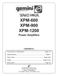
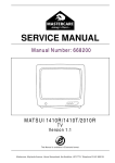
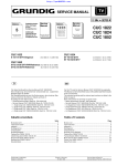
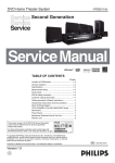
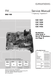
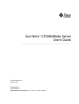
SERVICE MANUAL
Service
Manual
Sach-Nr./Part No.
72010-019.80
Service
Manual
Additionally
required Service
Manuals for the
Complete Service:
P14 - 6210/4
P14 - 6210/4 text
P14 - 6210/6
P14 - 6210/6 text
P14 - 6210/8
P14 - 6210/8 text
T20 - 6210/4
T20 - 6210/4 text
T20 - 6210/6
T20 - 6210/6 text
Safety
Sach-Nr./Part No.
72010-800.00
CUC 400
(9.21508-0302 / G.CD 3902)
(9.21508-0202 / G.CD 3602)
(9.21508-2202 / G.CE 0502)
(9.21509-0375 / G.CD 4075)
T20 - 6210/8
T20 - 6210/8 text
T51 - 721/5
T51 - 721/5 text
T21 - 6210/4
T21 - 6210/4 text
T21 - 6210/6
T21 - 6210/6 text
T21 - 6210/8
T21 - 6210/8 text
(9.21509-0275 / G.CD 3775)
(9.21509-0475 / G.CE 2375)
(9.21510-0375 / G.CD 4175)
(9.21510-0275 / G.CD 3875)
TP 711 (29642-062.01)
Subject to alteration
VK 221 / 0797
Service Manual Part No. 72010-019.80A
General Section
CUC 400
Table of Contents
Page
General Section .................................... 1-2…1-7
Safety Advice ...............................................................................
Circuit Diagram Symbols .............................................................
Technical Data .............................................................................
Operating Instructions ..................................................................
25Hz
1-2
1-2
1-3
1-4
Volume
Tint
Brightness
Alignments ..................................................... 2-1
Contrast
Layout of the PCBs
and Circuit Diagrams ........................... 3-1…3-7
Oscillograms Chassis Board ........................................................
General Circuit Diagram ..............................................................
Chassis Board PCB .....................................................................
CTR Panel PCB ...........................................................................
3-1
3-2
3-5
3-7
Spare Parts List .................................... 4-1…4-5
Colour contrast
AGC
AUDIO
AUDIO
OUT
Audio signal output
BB
Baseband
Coincidence
FBAS
CCVS signal
G
Green signal
The regulations and safety instructions shall be valid as provided
by the "Safety" Service Manual, part number 72010-800.00, as
well as the respective national deviations.
Horizontal synchronizing pulse
IF
Intermediate frequency
R
Red signal
SB
SCL
SDA
SOUND
IF
VERT.
SYNC
VIDEO
Beam current limiting
I2C-Bus Clock
I2C-Bus data
Sound intermediate frequency
Vertical synchronizing pulse
Video signal
VIDEO
IN
Video signal input
VIDEO
OUT
Video signal output
U
U
U
U
U
AV
Switching voltage AV
Switching voltage data mode
DATA
Switching voltage norm
NORM
Switching voltage standby
STBY
UHF
UHF switching voltage
Automatic frequency control voltage
U
AFC
Voltage synthesizer tuning
U
TUN.
Tuning voltage
TUN
Vertical amplitude
Blue signal
COIN
HOR.
SYNC1
Circuit Diagram Symbols
Audio signal
Audio signal input
General Section
The X-radiation developing in the sets conforms to the X-radiation
Regulations (January 8, 1987), issued by the Physikalisch-Technische
Bundesanstalt (federal physiotechnical institution).
The high tension for the picture tube and thus the developing Xradiation depends on the precise adjustment of the +A power supply.
After every repair of the power supply unit or the horizontal deflection
stage it is imperative that the EHT for the picture tube is checked and
re-adjusted if necessary.
To avoid consequential damages to the chassis or the picture tube
the integrated protective circuits are allowed to be put out of operation
only for a short time.
When replacing the picture tube use only the types specified in the
spare parts lists.
Automatic gain control
AUDIO
IN
B
Safety Advice
25Hz interlace signal
ADJ.
Delayed control voltage
U
U
VH
U
VL
Horizontal amplitude
Switching voltage VHF high band
Switching voltage VHF low band
Horizontal picture position
Vertical picture position
Vertical linearity
1-2
GRUNDIG Service
P14-6210/8
P14-6210/8 text
T20-6210/4
T20-6210/4 text
T20-6210/6
T20-6210/6 text
T20-6210/8
T20-6210/8 text
T 51-721/5
T 51-721/5 text
T21-6210/4
T21-6210/4 text
T21-6210/6
T21-6210/6 text
T21-6210/8
T21-6210/8 text
34cm
34cm
34cm
48cm
48cm
48cm
48cm
51cm
51cm
51cm
37cm (14")
37cm (14")
37cm (14")
51cm (20")
51cm (20")
51cm (20")
51cm (20")
55cm (21")
55cm (21")
55cm (21")
90°
90°
90°
90°
90°
90°
90°
90°
90°
90°
50Hz
50Hz
50Hz
50Hz
50Hz
50Hz
50Hz
50Hz
50Hz
50Hz
99 TV + 1 AV
99 TV + 1 AV
99 TV + 1 AV
99 TV + 1 AV
99 TV + 1 AV
99 TV + 1 AV
99 TV + 1 AV
99 TV + 1 AV
99 TV + 1 AV
99 TV + 1 AV
hyperband (optional)
hyperband
hyperband
hyperband (optional)
hyperband
hyperband
hyperband
hyperband (optional)
hyperband
hyperband
PAL/
NTSC 3.58 / 4.43MHz
B/G
PAL/SECAM/
NTSC 3.58 / 4.43MHz
B/G, D/K
PAL/SECAM/
NTSC 3.58 / 4.43MHz
B/G, D/K, M, I
PAL/
NTSC 3.58 / 4.43MHz
B/G
PAL/SECAM/
NTSC 3.58 / 4.43MHz
B/G, D/K
PAL/SECAM/
NTSC 3.58 / 4.43MHz
B/G, D/K, M, I
PAL/SECAM/
NTSC 4.43MHz
B/G, D/K
PAL/
NTSC 3.58 / 4.43MHz
B/G
PAL/
NTSC 3.58 / 4.43MHz
B/G
PAL/SECAM/
NTSC 3.58 / 4.43MHz
B/G, D/K, M, I
East / West
only model with text
East / West
only model with text
East / West
only model with text
East / West
only model with text
East / West
only model with text
East / West
only model with text
Cyrillic
only model with text
East / West
only model with text
East / West
only model with text
East / West
only model with text
3W
3W
3W
4W
4W
4W
4W
8W
8W
8W
Video IN / OUT
2 x Cinch
2 x Cinch
2 x Cinch
2 x Cinch
2 x Cinch
2 x Cinch
2 x Cinch
2 x Cinch
2 x Cinch
2 x Cinch
Audio IN / OUT
2 x Cinch
2 x Cinch
2 x Cinch
2 x Cinch
2 x Cinch
2 x Cinch
2 x Cinch
2 x Cinch
2 x Cinch
2 x Cinch
Mains voltage (variable)
90…270V
90…270V
90…270V
90…270V
90…270V
90…270V
90…270V
90…270V
90…270V
90…270V
Mains frequency
50 / 60Hz
50 / 60Hz
50 / 60Hz
50 / 60Hz
50 / 60Hz
50 / 60Hz
50 / 60Hz
50 / 60Hz
50 / 60Hz
50 / 60Hz
Power consumption
ca. 40W
ca. 40W
ca. 40W
ca. 55W
ca. 55W
ca. 55W
ca. 55W
ca. 60W
ca. 60W
ca. 60W
Standby
ca. 7W
ca. 7W
ca. 7W
ca. 7W
ca. 7W
ca. 7W
ca. 7W
ca. 7W
ca. 7W
ca. 7W
Picture Tube
Visible picture
Screen diagonale
Deflection angle
Vertical frequency
CUC 400
P14-6210/6
P14-6210/6 text
Technical Data
GRUNDIG Service
P14-6210/4
P14-6210/4 text
Electronic
Programme positions
Tuner
TV-Standard
Teletext
Music power
Connections Rear Panel
Mains Stage
General Section
1-3
General Section
1-4
Operating Instructions CUC 400
Note:
This chapter contains excerpts from the operating instructions. For further particulars please refer to the
appropriate user instructions.
LOCAL CONTROL OPERATION
1. Mains On/Off Switch.
PICTURE ADJUSTMENT MODE
Press the power switch 1 on the TV set. The indicator will light up. Program Press (
-) and (+
) simultaneously into picture adjustment mode.
number is automatically appears on upper left corner of the screen for With button (P+), the symbol and scale will be selected sequentially as follows :
approximately 5 seconds.
Press the power switch once again to switch off the set.
Brightness
Contrast
Colour
Tint (in case of NTSC)
Brightness.
2. Indicator - Operating (green*/red),
Standby (red).
Adjust to required analog level with (
3. Remote Sensor.
-) and (+
) simultaneously or no other local key is pressed for
Press (
approximately 5 seconds will go back to normal.
-), (+
4. (
volume.
-) and (+
) buttons.
) for setting the sound
5. ( P- ), ( P+) Program selection button.
6. Aerial input 75 Ohms.
7. Video Output.
8. Audio Output.
9. Video Input.
* For particular models
CUC 400
GRUNDIG Service
10. Audio Input.
CUC 400
GRUNDIG Service
REMOTE CONTROL UNIT
The Remote Control Unit is the Primary Control Unit of your TV receiver. It allows
you to operate all functions and setting.
1...9 (0/AV) Direct select program position
(also AV).
Standby On/Off.
-/+
Brightness, Contrast.
-/+
Colour, Tint.
PC/AUX Shift key for Contrast, Tint.
Hold down for 3 seconds to call up the
tuning system and program setting
data.
TXT
P+ / Pi
OK
Teletext On/Off.
Select program position.
DispIay program position.
Display sleep timer.
Teletext overview.
Hold down for 3 seconds to call up the
multifunction menu.
To confirm and store selected values.
Press and hold for 3 seconds to call up
optimum analogue parameters.
TUNING AND PROGRAMMING
Press the (PC/AUX) button for approx. 3 seconds. The programming menu appears,
active parameter will become red, and the other remain cyan. To terminate press
(PC/AUX) button for approx. 3 seconds to leave the menu at any position.
Press (0...9) or (P+ P-) buttons to select program number.
Press (PC/AUX) button to move to the next parameter.
Press (P+) button to select frequency band sequentially as follows:
VHF L
VHF H
UHF
VHF L
Press (PC/AUX) button to move to the next parameter.
Press (P+) button to select 'AUTO' (automatic tuning) or 'MANUAL' (manual
tuning).
Press (PC/AUX) button to move to the next parameter.
- +
buttons.
Start tuning with
- +
buttons are for manual tuning (positive and negative direction).
To start auto tuning with +
button and stop with
- , during this time you can
- button to reverse tuning for overjumped station.
press and hold
Press +
button again to continous auto tuning.
Press (PC/AUX) button to move to the next parameter.
SOUND SYSTEM
Press (P+) button to select system sequentially as follows:
BG
DK
I
M
BG
Press (PC/AUX) button to move to the next parameter.
STATION LABEL (particular model only)
- +
Volume.
1-5
General Section
Sound On/Off (muting).
Press (+
) buttons to select one of four digits and (P+), (P-) buttons to select
charactors.
Press (OK) button to call up the STORE mode.
General Section
1-6
STORE P_ _appears to request for the displayed number or a possibly new program SOUND MUTE
number (copy function is also possible).
By pressing the button (
) the sound can be cut off and press the same button
once to get the sound back.
You can activate this function by pressing (OK) button at any position.
Press OK, storage and display of the current programming menu.
SLEEP TIMER
Press (PC/AUX) button for approx. 3 seconds to leave the menu.
You can set the timer so that the TV is automatically switched off to Stand By mode
after a period of 5 to 120 minutes in steps of 5 minutes.
For example, if you wish to set the timer to switch off after 60 minutes, press the
button (i) for approximately 3 seconds till multifunction display is on the screen.
Press the button (i) to select symbol (
) change from cyan to red, then
repeatedly press (P+) to change the time from OFF to 60 minutes. The TV
automatically switches to stand by after 60 minutes. If you have made a wrong entry
and want to cancel the entry set the timer to (OFF).
During the timer is activated, you can recall the remaining time by pressing (i)
button once.
SECRET CODE
With a four digit secret code you can protect your TV against unauthorised use.
Press the button (i) for approx. 3 sec. till multifunction display is on the screen.
Press the button (i) to move to the 'key' symbol change from cyan to red.
Enter a four digits secret code via 0...9, confirm by OK button and leave the menu
with storage by pressing the button (i) for approx. 3 seconds.The 'XXXX' show that
the set will be locked after having been switched off once by mains button.
Erasing the secret code by entering the last code again.
NOTE
CUC 400
GRUNDIG Service
If you ever forget your secret code number, the key on the last page will help you. Pressing the button combinations as shown will cancel
the secret code and restore the unit back into operation. Please cut and keep this portion of cover in the safe custody immediately on
purchase.
PROGRAM NUMBER POSITION
VIDEO RECORDING
Select with (P+) or (P-) buttons to the required program number. For direct access
press the required program number on the key board. For two digit program number
(from 10 to 99) press the first digit and the second digit. The second digit should be
pressed immediately after the first, before the first digit with a '-' disappears from the
screen. AV programing can be accessed directly by pressing button (0/AV).
At the rear of the TV receiver are 2 sets of cinch sockets for video/audio in/out, see
page 6.
CUC 400
GRUNDIG Service
AV RECORDING & PLAYBACK
PICTURE & SOUND ADJUSTMENTS
Similarly in Video Cassette Recorders, sockets are provided for 'Video in' and
'Audio in'.
Press (i) button once. The program number position will be displayed on the left Interconnecting Cables between VCR & TV set are commercially available as
accessories. VCR manual should be referred to ensure that appropriate connectors
corner of the TV screen. The display will disappear after 5 seconds.
are used.
SOUND/VOLUME
For recording, connect
Adjust to required level with (+
) and (
-) buttons. The scale and symbol will be • 'Video out' from TV Receiver to 'Video in' of VCR/VCP.
indicated on the screen.
• 'Audio out' from TV Receiver to 'Audio in' of VCR/VCP.
BRIGHTNESS
Select the program you wish to record with (P+) or (P-) button.
-). The scale and brightness symbol will be displayed. Make suitable Start the VCR/VCP and operate in the recording mode as described in the operating
Press (+
manual for your VCR/VCP.
adjustment by pressing (+) for increase and (-) for decrease before the scale
disappears.
PLAYBACK IN AV MODE
CONTRAST
For VCR and VCP
Press (PC/AUX) button once then press (+
-).The scale and contrast symbol will For play back interconnect as follows :
be displayed. Make suitable adjustment by pressing (+) for increase and (-) for • 'Video in' socket 9 from Receiver to 'Video out' of VCR/VCP.
decrease before the scale disappears.
• 'Audio in' socket 10 from Receiver to 'Audio out' of VCR/VCP.
COLOUR
Press and hold button (P+) or (P-) or (AV) directly till display of 'AV' appears on the
Press (+
-). The scale and colour symbol will be displayed. Make suitable upper left hand corner of the TV screen. Start the VCR and operate it in the play
back mode as described in the operating manual for VCR.
adjustment by pressing (+) for increase or (-) for decrease before the scale
disappears.
PLAYBACK IN RF MODE
TINT
1-7
13
General Section
Connection - Connect "RF out" of VCR to "Aerial input" of TV.
Allocate the channel of VCR Output (Refer to your VCR Manual) to any program
be
(+
Press (PC/AUX) button once then press
-). The scale and tint symbol will
displayed. Make suitable adjustment by pressing (+) for increase or (-) for decrease position by channel search procedure as already explained.
before the scale disappears
Alignment
CUC 400
Alignments
All alignment controls not mentioned in this description are preset at the factory and must not be re-aligned in the case of repairs.
Measuring instruments: Oscilloscope with 10:1 test probe, high-resistance voltmeter, colour bar test pattern.
Cecks and alignments after replacement or repair of :
Power Supply: Power voltages must be checked after every repair and before every alignment. See alignment 1.1
Tuner, IF Amplifier: alignment 1.8
Vertical Deflection: alignment 1.4…1.6
Horizontal Deflection: alignment 1.2, 1.3, 1.7
IC201: alignment 1.2, 1.8, 1.9
F202: alignment 1.10
CRT Panel: alignment 1.2, 1.11
Preparations
Alignment
1.1
+A voltage
Brightness:
Contrast:
Volume:
Voltmeter:
minimum
minimum
minimum
D910 Cathode
1.2
Screen grid
voltage USG
Feed in a test pattern with grey scale
Align the screen brightness with the remote control
handset so that the grey aeras just become dark
(Switch the TV receiver to AV mode)
Oscilloscope: collector TR602/604/606
choose test point with the highest voltage level
Alignment Procedure
Set control VR901 to 124V ± 0.2V
With the control SG on DS-transformer set the voltage
to 110V (14") or 150V (20"/21")
Schwarzwert
Black level
110V
14"
105-110V
150V 20"/21"
1.3
Focus
Feed in a convergence test pattern
Contrast:
maximum
Brightness: medium
With the focus control FOC on DS-transformer align the
horizontal lines for maximum sharpness
1.4
Line width
Feed in a test pattern
Align picture-overscan to 2-3mm with L801
1.5
Vertical shift
Feed in a test pattern
Align picture to vertical middle position with VR703
1.6
Vertical
geometry
Feed in a test pattern
Align linearity with VR701 and amplitude to 2-3mm overscan with VR702
1.7
Horizontal
shift
Feed in a test pattern
Align test pattern to middle position with VR202
1.8
Tuner AGC
Feed in a standard test pattern UHF band channel 60;
the RF must be ≥1.5mV (64dBµV, noise-free picture)
With VR201 align voltage at IC201-(47) to maximum,
approx. 4.5V, and then reduce it by approx. 0.5V
1.9
Demodulator
filter
Disconnect contact 1 from tuner
With L203 align voltage to 2V
Feed in 38.9MHz from test generator to pin 1 from F201
Voltmeter :
IC201-(9)
Re-connect contact 1 to tuner after alignment
1.10
Sound trap
Feed in a NTSC picture (4.5MHz sound) without colour With L202 align to minimum
carrier
Oscilloscope:
emitter TR202
1.11
White balance
Feed in a colour test pattern
Colour contrast (E): minimum
Contrast (W):
maximum
Align the screen brightness (R) so that the gradation
from the darkest grey scale value to black is just still
visible
2-1
Set the controls VG (VR601) and VB (VR602) so that no
discolouration is visible in the grey scale
GRUNDIG Service
CUC 400
Layout of the PCBs and Circuit Diagrams
Layout of the PCBs and Circuit Diagrams
Oscillograms Chassis Board
1
0V
0V
3
2
0V
4
0V
6
0V
0V
1
2
8 9
3
4
10V/cm, 2µs/cm
1V/cm, 2µs/cm
100V/cm, 2µs/cm
1V/cm, 2µs/cm
5
8
10
0V
0V
9
11
0V
0V
500mV/cm, 20µs/cm
10 11
7
0V
6 7
2V/cm, 10µs/cm
0V
0V
12
2V/cm, 20µs/cm
100V/cm, 2µs/cm
13
1V/cm, 20µs/cm
line
1V/cm, 500µs/cm
picture
18
14
17
0V
0V
0V
15
0V
0V
16 17
5V/cm, 20µs/cm
1V/cm, 20µs/cm
19
16
0V
14
15
0V
5V/cm, 20µs/cm
test probe 100:1
18
19
5V/cm, 5ms/cm
10V/cm, 5ms/cm
20
1V/cm, 5ms/cm
R
0V
G
0V
B
0V
0V
0V
0V
21
1V/cm, 20µs/cm
22
2V/cm, 5ms/cm
23
2V/cm, 20µs/cm
24
5V/cm, 20µs/cm
R
SCL
0V
0V
G
0V
0V
B
0V
25
100V/cm, 20µs/cm
GRUNDIG Service
SDA
0V
0V
26
1V/cm, 100ns/cm
27
1V/cm, 10µs/cm
28
2V/cm, 200µs/cm
on text mode
3-1
Layout of the PCBs and Circuit Diagrams
CUC 400
OPTION FOR TELETEXT
General Circuit Diagram
15
22
+5V
C402
10n
F
C405
10u25V
13
2
7
21
18
19
20
25
26
27
IC401
11
TELETEXT
4
EEPROM
OPTION
+5V
+12V
3
8
K
C102
100n
STV5346/5348
3
17
16
6
5
10
8
9
12
1
14
1
R140
1K
LED1
RED
R101
270
R103
10K
R102
22K
R106
10K
R105
10K
R104
10K
IC104
7
5
VOL+
R107
220
R407
1K
R403
100
R413
100
4
24C04
SW4
R411
5K6
2
R405
1K
R404
12K
R406
12K
R408
3K3
R409
5K6
R414
5K6
K
C401
100n
6
R
3
SW5
DIODES
OPTION
VOL-
C107
K
C101
2
IC101
R401
4K7
D102
1N4148
100p
R110
68K
R402
4K7
R109
1K
R113
1K
100p
C112
100p
K
K
35
17
7
8
4K7
10
13
14
15
16
33
40
41
26
27
25
24
23
CT101
K
8p2
L101
56uH
C113
IC102
ST6377
GHK3
29
K
15p
39
F
34
18
19
20
37
21 30
11
1
9
2
R124
4K7
R1
19
1K5
K
R125
56K
R123
10K
D108
1N4148
F
C1
15
10n
R120
10K
3
R122
100K
C1
16
10u50V
4
R127
4K7
5
6
R133
2K2
R128
4K7
R137
33K
R130
18K
27
38
R134
12K
R131
5K5
R126
18K
36
R135
1K8
R132
18K
R138
47K
R162
2K2
R163
2K2
SYSTEM
/5;/6;/8
ONLY
R136
100K
A
B
5
C920
100p1KV
R901
4M7
K
K
FS902
T2AL
PCT901
DOUBLE PTC
F
C903
220u400V
C904
1n
400V AC
K
SW1-2
12K
K
C906
K 1n1KV
C908
1n1KV
F
L901
2X49mH
C901
0.15u250V AC
K
C907
1n1KV
C909
1n1KV
R913
4K7
D908
1
R903
1
F. BEAD
3
FS903
T2AL
C918
15n
R909
6
C924
220n
12
A
D
J
VO
C
1
IC902
LM317
F.BEAD
C932
2n2 400V AC
10K
VR901
2K
K
D909
5K6
220
C923
470u25V
L904
R910
R907
470
R908
BYW172D
VI
R91
1
56
4
C910
47u50V
C925
2n2
1
D911
15
9
10
R918
3K4 1%
K
R912
BYT53B
8
33K
C921
100u250V
C922
100p1KV
L903
TDA4605-3
4
6
CIRCUIT NOT MAINS-ISOLATED
D907
BYT54M
C915
470p2KV
PPN
TR901
BUZ90A
47
1
BYW178
R917
15K
F
R914
5
D901-D904
PC2010RX4
K
NTC901
4.7
3
R915
10
IC901
F.BEAD
D906
BYT54M
2
7
F
D910
F
D905
BYT53A
2n5
3
C91
1
100n
FS901
T3.15AL
K
C905
1n
400V AC
2
18
L905
R916
15K
C914
33n630V
C913
F
R906
SINGLE PTC
14" ONLY
4
C919
470p2KV
R905
270K
R904
680K
SW1-1
T901
LBV288/1
c.a. 320V
C902
0.1u250V AC
90V TO
260V AC
1
CNR3
R118
22
42
CNR8
2
28
32
COIL
3
R114
1K
Q101
8MHz
CNR7
4
R117
31
C1
14
100p
5
4K7
26
C106
470n
6
R116
4K7
F
C1
10
100n
D101
1N4148
+5V
7
C
R112
1K
D103
1N4148
C109
K
1
K
8
4K7
D107
1N4148
R108
100K
D104
1N4148
C108
K
100p
C105
27p
9
R115
+5V
D105
1N4148
3
K
10
SW3
TFMS5300
C104
27p
11
D106
1N4148
PRO-
100p
47u25V
12
28
SW2
PRO+
BYT53B
C916
1u63V
F
C917
3n9
1
C929
1u100V
IC903
L7805CV
VI
G VO
N
D
2
DIODE OPTION
REF
WITH DIODES
WITHOUT DIODES
D101
WITH LOGO
WITHOUT LOGO
D102
AV2V1,A
D103
MULTI SOUND IF
D105
D106
5.5MHz SOUND IF
TINT
D104
IMPORTANT CIRCUIT SYMBOLS
APPROX. VALUES
PIN ASSIGNMENT
1
TINT
15
KBCOL2
29
2
COLOUR
16
KBCOL3
30
TEST (GND)
3
BRIGHTNESS
17
KBCOL4
31
OSC-IN
4
CONTRAST
18
VHF LOW
32
5
VOLUME
___
AV1/AV2
19
VHF HIGH
33
OSC-OUT
_____
RESET
6
20
UHF
34
VS TUNING
7
KBROW0
21
GROUND (VSS)
35
8
KBROW1
22
RED-OUT
36
REMOTE IN
__
AV/TV
9
AFC IN
23
GREEN-OUT
37
POWER ON/OFF
10
KBROW2
24
BLUE-OUT
38
SOUND IF SELECT
11
TV STATUS
25
BLANKING
39
SOUND IF SELECT
12
N.C.
26
H-SYNC
40
SDA
13
KBCOL0
27
V-SYNC
41
SCL
14
KBCOL1
28
OSD OSC-IN
42
5V (VDD)
AV
1/8W
WIRE WOUND
NO TINT
HYPERBAND
NO HYPERBAND
POWER ON START
1/4W
POWER ON STANDBY
1/2W
CRT SOCKET
2--4V
FLAME RESISTANT
1--4V
NORM ASSIGNMENT
1W
CNR5
STANDARD
FUSIBLE
0--5V
U-NORM
A
B
1
B/G
1
1
2
D/K
1
0
3
I
0
1
4
M
0
0
2W
ELECTROLYTC
K
2--4V
CERAMIC
F
7W
FOIL
3--4V
OSD OSC-OUT
CRT SOCKET 22.5mm
3-2
GRUNDIG Service
CUC 400
Layout of the PCBs and Circuit Diagrams
1u25V
R164
33K
+12V
R165
33K
24
K
33p
6
16
10
11
1
Q401
13.875MHz
14
R408
3K3
K
33p
R412
100K
K
14
3
15
R168
1u100V
47
13
4
5
F
C118
220n
C502
3n3
R143
33K
R144
C141
100p
K
R141
10K
33K
F
C121
100n
C122
100n
+12V
R209
470
4
TUNER
TR102
BC558B
5
R173
7K5
L201*
1
1uH
R153
10K
R157
D110
BA282
SYSTEM
/8 ONLY
10K
R158
R159
6K8
+12V
18K
10
10K
C117
6K8
5
47u25V
4
R154
6K8
A
TR107
BC548B
R178
R179
470
75
R161
22K
R160
22K
5
F
12K
CNR6
J1
10K
12K
J2
#R607
2K7
10K
J3
#R616
2K7
10K
J4
#R625
2K7
10K
J5
#R632
6.2
6.8
J6
R608
270
D602
L602
2
4
11
R615
5K1
#R616
13
6
7
VR601
1K
K
1K
1K5
9
3
4
5
RED
CNR4
7
GND
6
8
1
GREEN
5
GND
4
BLUE
3
+12V
2
SW
1
K
R177
470
D202
1N4148
A
B
B
R620
C606
#R625
C212
100n
R621
R622
1K
1K5
C.A.
25KV
TR605
BF421
#TR606
VR602
1K
23
K
VB
R626
270
C608
680p
+5V
C214*
1u100V
+12V
R627
470
D604
10
24
+12V
1N4148
CNR10
3
F
SYSTEM
/4 ONLY
VIDEO
OUT
R630
1K5
1K
K
220p
1N4148
1K2
F203*
SFE 5.5MHz
D201
1N4148
D603
L603
R624
5K1
9O O
6
R617
270
C605
390p
150uH
9
H
7
R612
#TR604
1K2
C508
220n
15 14 12
8
J
CNR5
25
R613
TR603
BF421
R614
3
C126
100n
A51JSW90X03
1K5
R611
1K
K
220p
1N4148
C604
VG
IC204*
4052BP
TR108
BC558B
8
TR109
BC548B
10K
#R619
C602
390p
150uH
C507
2n2
R505
1
R502
100
16
SYSTEM
/8 ONLY
+12V
R176
4K7
3
1
4K7
K
F201*
1
2
#R610
1K
R623
R212
R171
1K
D1
11BA282
R156
1K5
C211
47p
AUDIO
OUT
220
C125
2n2
K
12K
+12V
TR202
BC558B
K
R175
R174
1K2
BFG71
10K
R504
F202
TPS 5.5MHz
C124
10u50V
3300KHC3X9751
8
R155
TR106
BC548B
ENV-578G9F2
TR103
BC558B
BF422
#R603
+12V
F204*
SFE 5.5MHz
TR105
BC548B
ANTENNA
6
R503
K
R506
220
F205*
SFE 6.5MHz
SYST
.
/4/5/6
ONLY
7
R172
22K
K
#R619
L202
15mH
R21
1
1K2
+12V
3
2
TR101
BC558B
R152
10K
3
#TR606
A48JLL90X01
R606
F206*
SFE 6.0MHz
82
K
C249
330p
+12V
C123
47u25V
2
1
BFG71
R210
150
L103
120uH
SYSTEM
/8
ONLY
TR201
BC548B
R217
R151
10K
R244
10K
C248
47p
33K
47K
F
TR104
PH2222
R142
3K3
R146
R145
L202
07202-405
K
BF422
TR601
BF421
#R610
C504
2.2u100V
R501
3K9
F207*
SFE 4.5MHz
#TR604
K
220p
#R607
R602
2K2
C506
470u16V
C505
0.47u100V
1K5
680
BFG71
C601
R601
10K
8
R220
D109
ZTK33A/KA33V
20"/21"
BF422
2
C501
100n
15K
R147
100K
14"
#TR602
#TR602
3n3
F
+124V
K
C120
47u50V
K
R216
360
R148
C119
100n
4
C503
K
470
22uH
MUTE
TDA7245A
TR203
BC558B
R215
560
L102
STAND
BY
7
C509
22u25V
1
6
10
11
12
13
14
15
16
17
18
9
R213
560
R214
#-PARTS
1K
+12V
CNR9
3
IC501
5
TR502
BC337
R169
75
+8V
33K
1
CNR3
C512
100u25V
R511
1K
R507
15K
21"
ONLY
R604
R605
VIDEO IN
R410
3K3
2
R510
1K
220n
C511
470u25V
D501
2.7V
1
C130
R508
4K7
TR501
BC558B
5K6
C129
470p
K
4053BP
R166
TR401
BC558
C401
100n
AUDIO IN
2
IC103
9
TR110
BC548B
8
12
C403
23
7
D502
2.7V
R167
150uH
F C510
A34JLL90X23
D601
1N4148
L601
#R603
+16.5V
6.2
C128
4.7u25V
C404
SPEAKER
14" 12 OHM
20"/21" 8 OHM
SPEAKER
8 OHM
R509
1u100V
28
Layout of the PCBs and Circuit Diagrams
+12V
C127
C406
CUC 400
+124V
14" ONLY
K C213
100p
2
A
GND
C610
4n71KV
K
1
+180V
20"/21"
ONLY
TER
#R632
HEATER
SG
FOC
B
T801
FLYBACK
FBT
+8V
R205
+124V
R206
27K
R207
47K
L203
19202-185
C201
100n
R218
22K
R208
1
R222
750
K
C203
100n
R919
390 1%
C925
2n2
C206
1n
6K8
K
R203
390
K
D912
1N4148
45
46
2
3
A
D
J
+12V
7
C210
10
C927
470u25V
C926
100n
R920
430 1%
4
7
16
15
13
5
1
C928
22u25V
3
VR201
5K
AGC
C931
220u16V
PIN 1
2,9V
PIN 19
2,5V
PIN 36
8,5V
PIN 2
6,2V
PIN 20
2,5V
PIN 37
4,2V
PIN 3
6,2V
PIN 21
0,2V
PIN 38
0,7V
PIN 4
6,2V
PIN 22
3,3V
PIN 39
2,9V
PIN 5
1,2V
PIN 23
3,3V
PIN 40
PIN 6
3,9V
PIN 24
3,3V
PIN 41
–
PIN 7
3,4V
PIN 25
2,0V
PIN 42
2,2V
PIN 8
1,8V
PIN 26
1,5V
PIN 43
2,9V
PIN 9
3,8V
PIN 27
2,5V
PIN 44
3,2V
8,4V
PIN 28
3,8V
PIN 45
4,2V
PIN 11
–
PIN 29
3,8V
PIN 46
4,2V
PIN 12
3,2V
PIN 30
1,5V
PIN 47
4,8V
PIN 13
4,4V
PIN 31
1,5V
PIN 48
3,9V
PIN 15
3,5V
PIN 32
1,7V
PIN 49
1,8V
PIN 16
0,0V
PIN 33
0,7V
PIN 50
3,5V
PIN 17
2,2V
PIN 34
1,4V
PIN 51
4,5V
PIN 18
2,5V
PIN 35
3,6V
PIN 52
6,5V
GRUNDIG Service
IC202
1,7V
PIN 3
8,5V
PIN 1
5,0V
PIN 7
3,4V
PIN 5
0,8V
PIN 8
4,2V
PIN 9
5,0V
PIN 9
1,4V
PIN 11
2,9V
PIN 10
1,5V
PIN 12
2,9V
PIN 15
0,7V
PIN 14
1,3V
PIN 16
5,7V
PIN 16
1,3V
10K
22uH
C706
R703
470
R
R227
R228
R705
22K
HORIZONTAL
DRIVE
TDA3653B
1
R816
33K
2
+26V
C703
14" 470U35V
20"/21" 1000U35V
19
3
C234
390p
F
5K6
F
C701
10n
3
16
C237
100n
52
F
C225
100n
K
33
35
C226
100n
C224
18p
(NPO)
R234
100K
F C228
BELL
PLL
S
W
I
T
C
H
DEEM
PHAS.
K
9
C242
K
10
C243
K
1
TUNING
7
8
K
C238
100n
CONTROL
TDA4665
LINESTORE
16
F
6
40
39
C231
1u100V
37
R806
1N4936
6.8
L804
TR206
BC558B
TR207
BC548B
R706
390
4
14
R708
3K9
18K
R712
10
C245
K
F
R238
100n
12
560K
C244
K
C233
100n
PLL
9
3K3
8
R237
+8V
C239
220n
TR208
BC558B
8K2
14
6.8
7
10
C805
F
22n50V
21"
J2
JH
17
JUMPER FOR R808 (14")
R808
820
L802
29203-114.04 (20")
29203-115.97 (21")
22
L803
F.BEAD
R710
680
VR702
100
R811
R711
1.8
VR703
10K
4K7
T802
TR801
BU508D
+12V
22
15
R814
C812
330
4.7u63V
C811
1n
TR802
BC637
K
D801
1N4148
/4
PAL
X
SECAM
NTSC 4.43
B/G
R813
120
+12V
SYSTEM
NTSC 3.58
16
R239
+8V
F
100n
C246
4n7
J1
J6
VR701
2K
8
JV
F
C710
1000u35V
C709
4.7u63V
R231
14" 470 2%
20"/21" 390 2%
F
R709
2
15uH
C807 420n
250n
R809 820/2W 1K5/4W
L801 -860.21 -850.21
L801
09246-
R707
1
C708
220n160VMKT
R232
K 510
2%
C235
680p
R230
10K
820K
VR202
10K
C232
10n
F
C711
47n
R229
1K
R235
18K
R805
F
C806
6n81600V
R809
J5
R243
10K
1
F
C807
160VPPN
C702
1n5
42
+8V
3
LINESTORE
5
43
10
11
1n
15
38
R236
1n
INT.
FACE
27
11
IC202
9
C241
100n
TDA8395
32
C229
18p
(NPO)
K
100n
1
K
31
K C230
4n7
R242
4.7
C240
100n
30
Q202
4.43MHz
+5V
R241
4.7
28
+12V
C227
4n7
SYSTEM
/4;/6;/8
ONLY
ACC
29
F
F
3
K
12
Q201
3.58MHz
IDENT
+8V
41
3
D701
K
390p400V
D803
BA157
R807
10K
9
C804 10
22u250V
2
C704
C808
680n250VPPN
F
4
R701
18
1
F
SW
K
5
F
20"/21"
ONLY
D804
BYV16 R804
CNR10
+180V
20"/21"
9
5
J62
J62
K
C705
100n
1N4936
IC701
1K
B
R803
10 C803
330n250VPPN
+124V
1M
R817
1K
D702
6
7
44
VERTICAL
DRIVE
8
R704
G
10K
PAL/NTSC-DECODER
11
34
IC203
SYSTEM /5;/6;/8 ONLY
C236
47u25V
270
R226
14
AMPLI.SEPARATOR
R233
+8V
8K2
SYSTEM /5; ONLY
PIN 1
3,6V
PIN 10
R225
+124V
+124V
14" ONLY
100u35V
+12V
20
J3
J4
14" / 20"
IC203
IC201
17
TDA8362A N3
AGC
+5V
C930
100n
25
3
IC201
C223
2.2u100V
F
C222
100n
K
2
26
18
48
R202
6K8
50
C802
220n
R815
TR803
BC548B
K
L906
51
F
+5V
R702
22K
100
49
+8V
R921
1K2 1%
IC903
L7805CV
VI
G VO
N
D
+8V
TR209
BC558B
4
1K
F
C801
220n
C707
220n
R240
5K1
C805
27p
FOC
SG
R802
+12V
R818
F
6
F
D703
4.7V
C221
2.2u100V
C215
10u50V
47
K
C247
1n
TR205
BC558B
3
21
TR902
BC337/25
C220
21
+8V
100
RGB
SWITCH
22
R922
15
10u50V
19
23
R201
2K2
8
R224
100K
VIDEO
IDENT
24
K
IC902
LM317
36
AFC
2
VO
K
D205
1N4148
4.7u25V
C217
2n7
6
C209
100n
K
9
1
VI
C207
100n
F 100n
K
8
4 1%
TR204
BC548B
R204
C204
12p
20
R223
100K
C219
C216
100n
C202
100n
+16.5V
4.7u25V
K
R219
47K
C208
470u10V
K
D204
1N4148
C218
+8V
100p
K
14" 13K
20"/21" 10K
R801
TER
33K
C205
K
R810
150
F
C810
2n2
F
C809
22n
R812
0.51
GRUNDIG Service
/8
X
X
X
X
X
X
X
X
X
X
X
F203*
F204*
F204*
F204*
F205*
F205*
F05*
I
F206*
M
F207*
IC204*
C214*
L201*
3-3
/6
X
X
D/K
SAW FILTER
F201*
12 13
/5
X
G1875M
2,2µH
X
X
K2955M
K2955M
K6259K
1µH
1µH
1µH
3-4
Layout of the PCBs and Circuit Diagrams
CUC 400
Layout of the PCBs and Circuit Diagrams
CUC 400
Chassis Board
Solder side, bottom view
18
6
13
12
7
14
28
9
8
10
26
27
20
11
19
22
15
21
2
16
17
4
1
3
5
3-5
GRUNDIG Service
3-6
GRUNDIG Service
CUC 400
Layout of the PCBs and Circuit Diagrams
Teletext
CRT Panel
R
0V
G
0V
B
0V
23
2V/cm, 20µs/cm
0V
24
25
23
5V/cm, 20µs/cm
24
R
0V
G
0V
B
0V
25
GRUNDIG Service
100V/cm, 20µs/cm
3-7
POS. NO.
NTC 901
D
7 / 96
Btx 32700 #
*
CUC 400
SACH-NR. / PART NO.: 25560-630.20
POS. NO.
FIG.
FIG.
IO PART NUMBER
QTY.
DESCRIPTION
TUNER
TUNER
PWR SW
PWR SW
FS901-03
AVIN/OUT
75990-700.30
75990-700.09
29633-682.01
29633-736.01
09621-113.02
75990-700.21
IO.26-403300-00
IO.26-257892-00
IO.11-068201-00
IO.11-063601-00
IO.12-050007-00
IO.44-060040-00
1
1
1
1
6
1
UHF/VHF/HYPER VS TUNER
U/V TUNER (ENV-578G9F2) f./4 T
POWER ON/OFF SWITCH KNOB 21“
POWER ON/OFF SWITCH KNOB 14" 20"
FUSE HOLDER
4 IN 1 RCA SOCKET
IC 101
IC 102
IC 103
IC 201
IC 202
IC 203
IC 204
IC 401
IC 401
IC 501
IC 701
IC 901
IC 903
IC 902
LED 1
L 202
L 203
L 801
L 801
L 802
L 901
8305-367-530
75990-700.10
6365-205-064
8305-338-362
8305-334-665
8305-338-395
6365-205-041
75990-700.29
75990-700.49
8305-367-245
8305-343-653
8305-354-605
8383-101-397
75990-700.18
75954-028.71
07202-405.10
19202-185.97
09246-850.21
09246-860.21
29203-115.97
75990-700.40
IO.29-005300-00
IO.29-006377-00
IO.29-014053-00
IO.29-008362-00
IO.29-004665-00
IO.29-008395-00
IO.29-014052-00
IO.29-005346-00
IO.29-005281-00
IO.29-007245-00
IO.29-003653-00
IO.29-004605-00
IO.29-007805-00
IO.29-100317-00
IO.31-520202-00
IO.36-402405-10
IO.36-353185-10
IO.33-461100-00
IO.33-437196-00
IO.33-480085-00
IO.42-349335-00
1
1
1
1
1
1
1
1
1
1
1
1
1
1
1
1
1
1
1
1
1
IC - TFMS 5300
IC - ST 6377 GHK3
IC - MC14053BCP/CD4053BP/
IC - TDA 8362 A N3
IC - TDA 4665
IC - TDA 8395
IC - MC14052BCP/CD4052BE/
IC - STV 5346
IC - SAA 5281 ZP/RM3/BALTIC/RUSSIAN
IC - TDA 7245 A
IC - TDA 3653 B
IC - TDA 4605/TDA 4605-3
IC - 7805 REGULATOR
IC - LM 317 REGULATOR
LED - RED Dia 3mm
IFT
(07202-405.10)
IFT
(19202-185.97)
HORIZONTAL WIDTH COIL
HORIZONTAL WIDTH COIL 14“ 20" T51
LINEARITY COIL
LINE FILTER 2X49mH 1.3A
VR 202
VR 702
VR 901
8792-002-151
8792-001-309
75990-700.38
IO.34-080103-00
IO.34-280101-00
IO.34-080202-00
1
1
1
TRIM.POTEN. 10K OHM 8mm H
TRIM.POTEN. 100 OHM 8mm V
TRIM.POTEN. 2K OHM 8mm H
SW-1
SW 2
SW 3
SW 4
SW 5
75990-700.39
29703-357.11
29703-357.11
29703-357.11
29703-357.11
IO.35-210204-00
IO.35-611105-00
IO.35-611105-00
IO.35-611105-00
IO.35-611105-00
1
1
1
1
1
POWER SWITCH WITHOUT M/C
MINIATURE TACT SWITCH
MINIATURE TACT SWITCH
MINIATURE TACT SWITCH
MINIATURE TACT SWITCH
F 201
F 202
F 204
F 205
F 206
F 207
8319-006-259
8602-755-021
19203-011.97
19203-013.97
19203-012.97
19203-014.97
IO.42-006259-00
IO.42-200552-00
IO.42-210552-00
IO.42-210652-00
IO.42-210602-00
IO.42-210452-00
1
1
1
1
1
1
SAW FILTER - OFW K6259K
CERAMIC TRAP - TPS 5.5MHZ
CER. FILTER - SFE 5.5MHZ
CER. FILTER - SFE 6.5MHZ
CER. FILTER - SFE 6.0MHZ
CER. FILTER - SFE 4.5MHZ
Q 201
Q 202
Q 401
Q 401
8382-047-004
8382-136-004
8382-501-138
75990-700.50
IO.42-413581-00
IO.42-414431-00
IO.42-401382-00
IO.42-400273-00
1
1
1
1
QUARTZ - 3.579545MHZ
QUARTZ - 4.433619MHZ
QUARTZ - 13.875MHZ
QUARTZ - 27.000MHZ/BALTIC/RUSSIAN
T 801
T 802
T 901
S
S
75990-700.16
75990-700.15
75990-700.17
IO.38-060481-00
IO.38-000401-00
IO.38-070488-00
1
1
1
FLYBACK TRANSFORMER
DRIVING TRANSFORMER
SWITCHING X’FORMER
PCT 901
PCT 901
S
S
75990-699.01
75990-700.22
IO.54-912180-00
IO.54-930000-00
1
1
PTC DOUBLE THERMISTOR
PTC 30 OHM(ZPB46BL300H)14“
IO PART NUMBER
QTY.
DESCRIPTION
8311-000-590
IO.54-947900-00
1
NTC 4.7 OHM
FS 903
FS 902
FS 901
S
S
S
8315-620-003
8315-620-003
8315-622-003
IO.62-232002-00
IO.62-232002-00
IO.62-233152-00
1
1
1
FUSE-SEMKO T 2.0AL 20x5mm
FUSE-SEMKO T 2.0AL 20x5mm
FUSE-SEMKO T 3.15AL 20x5mm
R 241
R 242
R 509
R 632
R 632
R 711
R 804
R 806
R 807
R 809
R 811
R 901
R 922
S
S
S
S
S
S
S
S
S
S
S
S
S
8700-199-017
8700-199-017
8700-199-023
75990-700.51
75990-700.52
8700-199.007
75990-700.41
75990-700.53
75990-700.54
75990-700.56
8700-199-033
8766-349-161
8700-199-029
IO.64-847935-00
IO.64-847935-00
IO.64-862955-00
IO.64-862955-00
IO.64-868955-00
IO.64-818965-00
IO.64-810045-00
IO.64-868955-00
IO.64-810335-00
IO.64-482165-00
IO.64-822035-00
IO.8766-349-16
IO.64-815035-00
1
1
1
1
1
1
1
1
1
1
1
1
1
FUSIBLE RES. 1/4W 4.7 OHM 5%
FUSIBLE RES. 1/4W 4.7 OHM 5%
FUSIBLE RES. 1/4W 6.2 OHM 5%
FUSIBLE RES. 1W 6.2 OHM 5% 14“
FUSIBLE RES. 1W 6.8 OHM 5% 20“
C.F.RES
1/4W 1.8 OHM 5%
FUSIBLE RES. 1/2 W 10 OHM 5%
FUSIBLE RES. 1W 6.8 OHM 5%
FUSIBLE RES. 1/4W 10 KOHM 5%
M. O. RES.
2W 820 OHM 5%
FUSIBLE RES. 1/4W 22 OHM 5%
C.F.RES LI 0414 4.7M OHM VDE
FUSIBLE RES. 1/4W 15 OHM 5%
TR 101
TR 102
TR 103
TR 104
TR 105
TR 106
TR 107
TR 108
TR 109
TR 110
TR 201
TR 202
TR 203
TR 204
TR 205
TR 206
TR 207
TR 208
TR 209
TR 501
TR 502
TR 801
TR 802
TR 803
TR 901
TR 902
8302-201-579
8302-201-579
8302-201-579
8302-920-223
8302-201-553
8302-201-553
8302-201-553
8302-201-579
8302-201-553
8302-201-553
8302-201-553
8302-201-579
8302-201-579
8302-201-553
8302-201-579
8302-201-579
8302-201-553
8302-201-579
8302-201-579
8302-201-579
8303-272-337
8302-260-508
8303-285-637
8302-201-553
8302-269-092
8303-272-337
IO.70-200558-00
IO.70-200558-00
IO.70-200558-00
IO.70-002222-00
IO.70-200548-00
IO.70-200548-00
IO.70-200548-00
IO.70-200558-00
IO.70-200548-00
IO.70-200548-00
IO.70-200548-00
IO.70-200558-00
IO.70-200558-00
IO.70-200548-00
IO.70-200558-00
IO.70-200558-00
IO.70-200548-00
IO.70-200558-00
IO.70-200558-00
IO.70-000558-00
IO.70-000337-00
IO.30-100508-00
IO.70-000637-00
IO.70-200548-00
IO.30-100090-00
IO.70-000337-00
1
1
1
1
1
1
1
1
1
1
1
1
1
1
1
1
1
1
1
1
1
1
1
1
1
1
TRANSISTOR - BC 558 B
TRANSISTOR - BC 558 B
TRANSISTOR - BC 558 B
TRANSISTOR - PH 2222
TRANSISTOR - BC 548 B
TRANSISTOR - BC 548 B
TRANSISTOR - BC 548 B
TRANSISTOR - BC 558 B
TRANSISTOR - BC 548 B
TRANSISTOR - BC 548 B
TRANSISTOR - BC 548 B
TRANSISTOR - BC 558 B
TRANSISTOR - BC 558 B
TRANSISTOR - BC 548 B
TRANSISTOR - BC 558 B
TRANSISTOR - BC 558 B
TRANSISTOR - BC 548 B
TRANSISTOR - BC 558 B
TRANSISTOR - BC 558 B
TRANSISTOR - BC 558
TRANSISTOR BC 337-25
TRANSISTOR - BU 508 D
TRANSISTOR - BC 637
TRANSISTOR - BC 548 B
MOS FET - BUZ 90 A
TRANSISTOR BC 337-25
D 101
D 103
D 104
D 105
D 106
D 107
D 108
D 110
D 111
D 201
D 202
D 204
D 205
D 501
D 502
D 701
D 702
D 703
D 801
D 803
D 804
D 901
D 902
D 903
D 904
8309-215-045
8309-215-045
8309-215-045
8309-215-045
8309-215-045
8309-215-045
8309-215-045
8309-201-283
8309-201-283
8309-215-045
8309-215-045
8309-215-045
8309-215-045
8309-707-505
8309-707-505
8309-210-138
8309-210-138
8309-707-012
8309-215-045
8309-201-005
8309-204-268
75990-700.42
75990-700.42
75990-700.42
75990-700.42
IO.71-204148-00
IO.71-204148-00
IO.71-204148-00
IO.71-204148-00
IO.71-204148-00
IO.71-204148-00
IO.71-204148-00
IO.71-200282-00
IO.71-200282-00
IO.71-204148-00
IO.71-204148-00
IO.71-204148-00
IO.71-204148-00
IO.71-445279-00
IO.71-445279-00
IO.71-204936-00
IO.71-204936-00
IO.71-445479-00
IO.71-204148-00
IO.71-200157-00
IO.71-200016-00
IO.71-302007-00
IO.71-302007-00
IO.71-302007-00
IO.71-302007-00
1
1
1
1
1
1
1
1
1
1
1
1
1
1
1
1
1
1
1
1
1
1
1
1
1
DIODE - 1N 4148
DIODE - 1N 4148
DIODE - 1N 4148
DIODE - 1N 4148
DIODE - 1N 4148
DIODE - 1N 4148
DIODE - 1N 4148
DIODE - BA 282
DIODE - BA 282
DIODE - 1N 4148
DIODE - 1N 4148
DIODE - 1N 4148
DIODE - 1N 4148
ZENER DIODE - 2V7 0.5W 5%
ZENER DIODE - 2V7 0.5W 5%
DIODE - 1N 4936
DIODE - 1N 4936
ZENER DIODE - 4V7 0.5W 5%
DIODE - 1N 4148
DIODE - BA 157
DIODE - BYV 16
DIODE - RF 2007 (PS2010R)
DIODE - RF 2007 (PS2010R)
DIODE - RF 2007 (PS2010R)
DIODE - RF 2007 (PS2010R)
CUC 400
GRUNDIG Service
PART NUMBER
PART NUMBER
Spare Parts List
4-1
Ersatzteilliste
Spare Parts List
FIG.
D 905
D 906
D 907
D 908
D 909
D 910
D 911
D 912
C 804
C 901
C 902
C 904
C 905
C 921
C 932
S
S
S
S
S
PART NUMBER
IO PART NUMBER
QTY.
DESCRIPTION
8309-516-753
8309-516-854
8309-516-854
8309-516-754
8309-516-754
8309-517-178
8309-517-172
8309-215-045
IO.71-201053-00
IO.71-200054-00
IO.71-200054-00
IO.71-202053-00
IO.71-202053-00
IO.71-200178-00
IO.71-200172-00
IO.71-204148-00
1
1
1
1
1
1
1
1
DIODE - BYT 53 A
DIODE - BYT 54 M
DIODE - BYT 54 M
DIODE - BYT 53 B
DIODE - BYT 53 B
DIODE - BYW 178
DIODE - BYW 172D
DIODE - 1N 4148
75990-700.43
75990-700.28
75990-700.55
8660-098-234
8660-098-234
75990-700.25
75990-700.27
IO.95-222627-00
IO.95-415427-00
IO.95-410427-00
IO.95-110236-00
IO.95-110236-00
IO.95-010727-00
IO.95-122237-00
1
1
1
1
1
1
1
HV-ELE.CAP. 22uF 20% 250V
VDE AC CAP. 0.15uF 250VAC
VDE AC CAP. 0.1uF 250VAC
VDE C.CAP. 1nF 10% 400VAC
VDE C.CAP. 1nF 10% 400VAC
HRC-E.CAP. 100uF250V665mA
VDE C.CAP.2.2nF20% 400VAC
CUC 400
GRUNDIG Service
POS. NO.
Ersatzteilliste
Spare Parts List
D
7 / 96
Btx 32700 #
*
P 14-6210/4
P 14-6210/4 text
P 14-6210/6
P 14-6210/6 text
P 14-6210/8
P 14-6210/8 text
SACH-NR. / PART NO.: 25560-660.00
POS. NO.
FIG.
PART NUMBER
IO PART NUMBER
QTY.
DESCRIPTION
1
2
3
4
5
6
7
8S
9S
75990-700.00
75990-700.01
29501-664.01
29632-082.01
75990-700.02
29620-017.01
75990-700.03
09246-170.73
8300-020-039
29642-062.01
IO.11-017391-00
IO.11-029511-00
IO.11-066401-00
IO.11-078201-00
IO.14-018701-00
IO.22-105103-00
IO.57-140512-00
IO.91-060334-00
IO.8300-020-039
IO.29642-062.01
1
1
1
1
1
1
1
1
1
1
FRONT CABINET 14“ CUC-400
BACK CABINET 14“ CUC-400
4 IN 1 UP/DOWN UNIT
GRUNDIG LOGO 14“
IR WINDOW
TELESCOPE ANTENNA
SPEAKER - 4“ 12 OHM 1.5W
DEGAUSSING COIL 14“
A 34 JLL 90X23 ORION 14“
REMOTE CONTROL TP-711
25560-630.20
25560-205.42
X
X
CUC 400
PICTURE TUBE BOARD
72010-019.80
SERVICE MANUAL
X = SEE SEPARATE PARTS LIST
()
The regulations and safety instructions shall be
valid as provided by the "Safety" Service Manual,
part number 72010-800.00, as well as the respective
national deviations.
Es gelten die Vorschriften und Sicherheitshinweise
gemäß dem Service Manual "Sicherheit", Sach-Nummer 72010-800.00, sowie zusätzlich die eventuell
abweichenden, landesspezifischen Vorschriften!
()
The regulations and safety instructions shall be
valid as provided by the "Safety" Service Manual,
part number 72010-800.00, as well as the respective
national deviations.
Spare Parts List
4-2
Es gelten die Vorschriften und Sicherheitshinweise
gemäß dem Service Manual "Sicherheit", Sach-Nummer 72010-800.00, sowie zusätzlich die eventuell
abweichenden, landesspezifischen Vorschriften!
Ersatzteilliste
Spare Parts List
D
7 / 96
Btx 32700 #
*
T 20-6210/4
T 20-6210/4 text
T 20-6210/6
T 20-6210/6 text
T 20-6210/8
T 20-6210/8 text
D
7 / 96
FIG.
PART NUMBER
IO PART NUMBER
QTY.
DESCRIPTION
1
2
4
5
7
8S
9S
75990-700.45
75990-700.46
29632-114.01
75990-700.02
75990-700.47
09246-171.73
8300-020-315
29642-062.01
IO.11-017381-00
IO.11-029441-00
IO.11-071401-00
IO.14-018701-00
IO.57-140808-01
IO.91-060776-00
IO.8300-020-315
IO.29642-062.01
1
1
1
1
1
1
1
1
FRONT CABINET 20“ CUC-400"
BACK CABINET 20“ CUC-400"
GRUNDIG LOGO 20“/21"
IR WINDOW
SPEAKER - 4“ 8 OHM 4W“
DEGAUSSING COIL
A48JLL90X01 20“ ORION“
REMOTE CONTROL TP-711
25560-630.20
25560-205.42
X
X
CUC 400
PICTURE TUBE BOARD
72010-019.80
SACH-NR. / PART NO.:
POS. NO.
FIG.
1
2
3
4
5
6
7
8
9S
10 S
PART NUMBER
IO PART NUMBER
QTY.
75990-700.31
75990-700.32
75990-700.33
29632-114.01
29633-431.01
75990-700.34
75990-700.35
75990-700.36
8300-020-534
09246-171.73
29642-062.01
IO.11-017491-00
IO.11-029731-00
IO.11-064401-00
IO.11-071401-00
IO.14-013101-00
IO.12-081281-00
IO.12-081291-00
IO.57-160908-00
IO.8300-020-534
IO.91-060776-00
IO.29642-062.01
1
1
1
1
1
1
1
2
1
1
1
FRONT CABINET 21“ CUC-400
BACK CABINET 21“ CUC-400
4 IN 1 UP/DOWN UNIT
GRUNDIG LOGO 20“/21"
IR WINDOW
SPEAKER GRILL - LEFT
SPEAKER GRILL - RIGHT
SPEAKER 6“ X 2.25" 8 OHM
A 51LSW90X03 21“ ORION
DEGAUSSING COIL
REMOTE CONTROL TP-711
25560-630.20
25560-205.42
X
X
CUC 400
PICTURE TUBE BOARD
SERVICE MANUAL
X = SEE SEPARATE PARTS LIST
*
T 21-6210/4
T 21-6210/4 text
T 21-6210/6
T 21-6210/6 text
T 21-6210/8
T 21-6210/8 text
SACH-NR. / PART NO.: 25560-660.10
POS. NO.
Btx 32700 #
Spare Parts List
4-3
Ersatzteilliste
Spare Parts List
72010-019.80
DESCRIPTION
SERVICE MANUAL
X = SEE SEPARATE PARTS LIST
()
The regulations and safety instructions shall be
valid as provided by the "Safety" Service Manual,
part number 72010-800.00, as well as the respective
national deviations.
Es gelten die Vorschriften und Sicherheitshinweise
gemäß dem Service Manual "Sicherheit", Sach-Nummer 72010-800.00, sowie zusätzlich die eventuell
abweichenden, landesspezifischen Vorschriften!
()
The regulations and safety instructions shall be
valid as provided by the "Safety" Service Manual,
part number 72010-800.00, as well as the respective
national deviations.
CUC 400
GRUNDIG Service
Es gelten die Vorschriften und Sicherheitshinweise
gemäß dem Service Manual "Sicherheit", Sach-Nummer 72010-800.00, sowie zusätzlich die eventuell
abweichenden, landesspezifischen Vorschriften!
Ersatzteilliste
Spare Parts List
D
7 / 96
Btx 32700 #
*
T 51-721/5
T 51-721/5 text
7 / 96
PICTURE TUBE BOARD
SACH-NR. / PART NO.: 25560-660.10
POS. NO.
SACH-NR. / PART NO.:
FIG.
PART NUMBER
IO PART NUMBER
QTY.
DESCRIPTION
POS. NO.
1
2
3
4
5
7
8S
9S
75990-700.45
75990-700.46
29501-664.01
29632-114.01
75990-700.02
75990-700.47
09246-171.73
8300-020-534
29642-062.01
IO.11-017381-00
IO.11-029441-00
IO.11-066401-00
IO.11-071401-00
IO.14-018701-00
IO.57-140808-01
IO.91-060776-00
IO.8300-020-315
IO.29642-062.01
1
1
1
1
1
1
1
1
1
FRONT CABINET 20“ CUC-400
BACK CABINET 20“ CUC-400
4 IN 1 UP/DOWN UNIT
GRUNDIG LOGO 20“/21"
IR WINDOW
SPEAKER - 4“ 8 OHM 4W
DEGAUSSING COIL
A 51 JSW 90X 03 ORION 20“
REMOTE CONTROL TP-711
25560-630.20
25560-205.42
X
X
CUC 400
PICTURE TUBE BOARD
72010-019.80
PART NUMBER
IO PART NUMBER
QTY.
DESCRIPTION
TR 601
TR 602
TR 602
TR 602 OPTIONAL
TR 603
TR 604
TR 604
TR 604 OPTIONAL
TR 605
TR 606
TR 606
TR 606 OPTIONAL
8302-220-421
8302-220-422
8302-220-871
75990-700.44
8302-220-421
8302-220-422
8302-220-871
75990-700.44
8302-220-421
8302-220-422
8302-220-871
75990-700.44
IO.70-000421-00
IO.70-000422-00
IO.70-000881-00
IO.30-004357-00
IO.70-000421-00
IO.70-000422-00
IO.70-000881-00
IO.30-004357-00
IO.70-000421-00
IO.70-000422-00
IO.70-000881-00
IO.30-004357-00
1
1
1
1
1
1
1
1
1
1
1
1
TRANSISTOR - BF 421
TRANSISTOR - BF 422 14“
TRANSISTOR - BFG 71/BF881 20/21“
TRANSISTOR - ON 4357 20/21“
TRANSISTOR - BF 421
TRANSISTOR - BF 422
14“
TRANSISTOR - BFG 71/BF881 20/21“
TRANSISTOR - ON 4357 20/21“
TRANSISTOR - BF 421
TRANSISTOR - BF 422
14“
TRANSISTOR - BFG 71/BF881 20/21“
TRANSISTOR - ON 4357 20/21“
CNR 5
75990-700.05
IO.45-500012-11
1
CRT SOCKET - 22.5mm NECK
75990-700.07
IO.64-862955-00
1
FUSIBLE RES. 1 W 6.2 OHM 5%
D 601
D 602
D 603
D 604
8309-215-045
8309-215-045
8309-215-045
8309-215-045
IO.71-204148-00
IO.71-204148-00
IO.71-204148-00
IO.71-204148-00
1
1
1
1
DIODE - 1N 4148
DIODE - 1N 4148
DIODE - 1N 4148
DIODE - 1N 4148
L 601
L 602
L 603
75990-300.06
75990-300.06
75990-300.06
IO.73-315121-00
IO.73-315121-00
IO.73-315121-00
1
1
1
CHOKE COIL - 150uH
CHOKE COIL - 150uH
CHOKE COIL - 150uH
C 610
75990-700.06
IO.96-147258-00
1
HV-CER.CAP. 4.7nF 1KV Z
SERVICE MANUAL
R 632
X = SEE SEPARATE PARTS LIST
()
The regulations and safety instructions shall be
valid as provided by the "Safety" Service Manual,
part number 72010-800.00, as well as the respective
national deviations.
FIG.
S
Es gelten die Vorschriften und Sicherheitshinweise
gemäß dem Service Manual "Sicherheit", Sach-Nummer 72010-800.00, sowie zusätzlich die eventuell
abweichenden, landesspezifischen Vorschriften!
()
The regulations and safety instructions shall be
valid as provided by the "Safety" Service Manual,
part number 72010-800.00, as well as the respective
national deviations.
Spare Parts List
4-4
Es gelten die Vorschriften und Sicherheitshinweise
gemäß dem Service Manual "Sicherheit", Sach-Nummer 72010-800.00, sowie zusätzlich die eventuell
abweichenden, landesspezifischen Vorschriften!
CUC 400
GRUNDIG Service
Ersatzteilliste
Spare Parts List
Spare Parts List
Subject to alteration
CUC 400
Printed in Germany
VK 221 0797
Service Manual Part No. 72010-019.80A