1
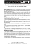
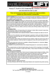
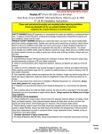
ReadyLift® (Part# 66-2515 & 66-2516) Installation Instructions
SAFETY WARNING:ReadyLift Suspension Inc. recommends this system be installed by a professional technician. In addition to these instructions, professional knowledge of disassembly/ reassembly procedures and
post installation checks must be known.
PRODUCT SAFETY WARNING:Modifying your vehicle ride height may result in the vehicle handling differently than a factory equipped vehicle. Extreme care must be used to prevent loss of control or vehicle rollover.
Failure to drive your modified vehicle safely may result in serious injury or death. ReadyLift Suspension Inc.
does not recommend the combined use of suspension lifts, body lifts, or other lifting devices. You should
never operate your modified vehicle under the influence of alcohol or drugs. Always drive your modified vehicle
at reduced speeds to ensure your ability to control your vehicle under all driving conditions. Always wear your
seat belt.
Pre-Installation Notes
1. Special literature required: OE Service Manual for model/year of vehicle. Refer to manual for proper disassembly/reassembly procedures of OE and related components.
2. Adhere to recommendations when replacement fasteners, retainers and keepers are called out in the OE
manual.
3. Larger rim and tire combinations may increase leverage on suspension, steering, and related components.
When selecting combinations larger than OE, consider the additional stress you could be inducing on the OE
and related components.
4. Post suspension system vehicles may experience drive line vibrations. Angles may require tuning, slider on
shaft may require replacement, shafts may need to be lengthened or trued, and U-joints may need to be replaced.
5. Secure and properly block vehicle prior to installation of ReadyLift Suspension Inc. components. Always
wear safety glasses when using power tools.
6. If installation is to be performed without a hoist, ReadyLift aSuspension Inc. recommends rear alterations
first.
7. Due to payload options and initial ride height variances, the amount of lift is a base figure. Final ride height
dimensions may vary in accordance to original vehicle attitude. Always measure the attitude prior to beginning
installation.
POST-INSTALATION WARNINGS
1. Check all fasteners for proper torque. Check to ensure for adequate clearance between all rotating, mobile,
fixed, and heated members. Verify clearance between exhaust and brake lines, fuel lines, fuel tank, floor
boards and wiring harness. Check steering gear for clearance. Test and inspect brake system.
2. Perform steering sweep to ensure front brake hoses have adequate slack and do not contact any rotating,
mobile or heated members. Inspect rear brake hoses at full extension for adequate slack. Failure to perform
hose check/ replacement may result in component failure. Longer replacement hoses, if needed can be purchased from a local parts supplier.
3. Headlight adjustment is highly recommended.
4. Re-torque all fasteners after 500 miles. Always inspect fasteners and components during routine servicing.
ReadyLift Suspension, Inc
ReadyLift® (Part# 66-2515 & 66-2516) Installation Instructions
Please read instructions thoroughly and completely before beginning installation.
Check www.readylift.com for any updated installation instructions.
Installation by a trained mechanic is recommended.
Torque Specs in FT/LB
Bolt
Size
Millimeters
Metric Grade Metric
8.8
Grade 10.9
6mm
6
8
8mm
16
22
10mm
40
45
12mm
54
70
14mm
89
117
16mm
132
175
18mm
182
236
Bill of Materials
Description
Qty
Metal coil spacer
Polyurethane sound insulator
Shock extension bracket
M14 x 90mm bolt
M14 Washer
M14 Nylon lock nut
16mm carrier bearing spacer
7/16x2 1/4 bolt
Bump stop extension bracket
M8x1.25 Nylon lock nut
05-07 F350 Pan hard bracket (66-2515 only)
08-09 F350 Pan hard bracket (66-2516 only)
Inner Fender Liner brackets w/ hardware
ReadyLift Suspension, Inc
2
2
2
2
4
2
1
2
2
1
1
1
2
ReadyLift® (Part# 66-2515 & 66-2516) Installation Instructions
Please read instructions thoroughly and completely before beginning installation.
Installation by a trained mechanic is recommended.
Position truck on a flat surface and lift vehicle by the frame until the front wheels are off
the ground. Using a floor jack and support the frame with jack stands, or a (2) two post
lift if available. Two jacks may be needed to lift and lower the front differential during
installation.
1.
Remove front wheels. Remove the lower
shock bolt.
You can use a jack to lift the differential and
release any pressure on the lower shock
bolt making the removal easier.
2.
With the jack still supporting the axle, unbolt
the 13mm brake line support bracket from
the frame on both sides.
2005-2007 Fig A
2008 Fig B
3.
Remove upper track bar 30mm bolt.
Fig B
Fig A
Remove this bolt.
Remove this bolt.
Remove sway bar end link bolt on both
sides. 19mm, 21
4.
5.
Lower differential and remove spring.
Install Readylift® coil spacer.
(Order of assembly: Coil(A), factory isolator
(B), coil spacer(C), polyurethane donut(D).)
Reinstall coil and raise differential.
Install shock extension onto shock using the
hardware provided. Please note that there is a
driver and passenger side shock extension.
Look for the D and P stamped on the inside
leg of the brackets. Install shock extension
bracket into factory shock mounting location on
the axle using the factory hardware. Torque to
factory specs.
ReadyLift Suspension, Inc
D
B
A
C
ReadyLift® (Part# 66-2515 & 66-2516) Installation Instructions
Please read instructions thoroughly and completely before beginning installation.
Installation by a trained mechanic is recommended.
6.
7.
Track Bar
Remove the two 19mm bolts on the factory
track bar bracket (one on each side of the
track bar mount).
Remove the three 21mm nuts located on the
cross member.
Remove track bar bracket. Install ReadyLift® track bar bracket using the factory
hardware.
Using factory hardware re-install track bar
onto the new ReadyLift® track bar bracket.
Re-install sway bar end links.
Torque to factory specs.
8.
Remove OEM front bump stops.
Remove the 10mm bolts that attach the
bump stop brackets to the frame.
Install ReadyLift® bump stop extension
bracket. Use a Phillips screw driver to
tighten.
Install OEM bump stop bracket using nut
provided. Install OEM bump stop.
9.
2005-2007 Models - Reinstall brake line
support brackets.
2008 models drill 3/8” hole approximately
2” below the factory hole, use the factory
self-tapping screw to re-attach the brake
line support bracket.
ReadyLift Suspension, Inc
Driver side
Passenger side
OEM Hole
OEM Hole
ReadyLift® (Part# 66-2515 & 66-2516) Installation Instructions
Please read instructions thoroughly and completely before beginning installation.
Installation by a trained mechanic is recommended.
10.
Remove the two 15mm bolts, use a
jack stand to support the drive shaft.
Install the ReadyLift® carrier bearing
spacer using the hardware provided.
Torque to factory specifications.
Be sure to double check that all hardware has been tightened and torqued to
factory specs.
Remount wheels and tires and torque to factory specs. Re-torque wheels after
25 miles.
*See next page for Tire and Wheel fitment specifications.
Wheel Alignment; a Certified Alignment Technician that is experienced with
lifted vehicles is recommended to perform the alignment.
*It is recommended that you have your vehicle’s alignment checked whenever
installing new tires.
*It is also recommended that you adjust your headlights whenever your vehicle’s
ride height is altered.
Vehicle Handling
Warning
Vehicles with larger
wheels and tires will
handle differently than
stock vehicles. Take
time to familiarize
yourself with the handling of your vehicle.
DRIVE SAFELY and
WEAR YOUR SEATBELT.
ReadyLift Suspension, Inc.
3201 W. MacArthur Blvd, Santa Ana, CA, 92704
Toll Free (888)922-2294 Fax 714-8622972
Installation
Warning
Always wear proper
safety equipment and
use the correct tools
when installing any
suspension upgrade.
Make sure vehicle is
on a flat surface and
you are using jack
stands or a lift rated
for the weight of the
vehicle.
Warning! This ReadyLift® Leveling Kit is designed and engineered to level out a
stock vehicle with no prior modifications. The use of this kit along with items
such as suspension lifts , body lifts or any other type of lifting accessory shall
be done at the vehicles owners risk and will void any and all warranties in effect
or implied by ReadyLift®. This kit is not for off road abuse.
ReadyLift Suspension, Inc
ReadyLift® (Part# 66-2515 & 66-2516) Installation Instructions
Please read instructions thoroughly and completely before beginning installation.
Installation by a trained mechanic is recommended.
Tire and Wheel Fitment
For 35” tires: 35x12.50 Mounted on a wheel no wider than 9.5” with 0 offset or 5.25”
backspacing.
For 37” tires: 37x12.50 Mounted on the factory wheel or on a wheel no wider than 8”
with a +35 offset or 6” backspacing. Please note that with this fitment the tire will
rub a little at full turn on the radius arm.
You will also need to pull the inner fender liner back with both of these fitments.
The best way to accomplish this is to install the ReadyLift® inner fender liner support
kit. Drill an 1/8” hole on the inner lip of the fender liner and an 1/8” hole on the underside of the body. Using the self-tapping screw and speed clip provided attach the
bracket to the fender liner then attach the other end to the body. See photos below.
Alignment Specs
Toe Left:
1/32
Toe Right
1/32
ReadyLift Suspension, Inc