1
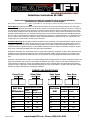
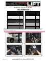
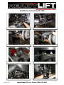
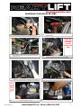
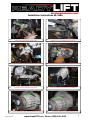
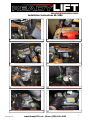
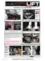
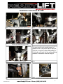
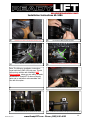
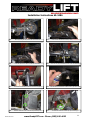
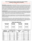
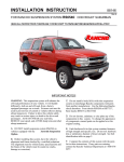
Installation Instructions 69-3486
WARNING TO END USER, INSTALLER
AND SELLER OF THIS PART!
By installing this part you are accepting full responsibility and liability for proper wheel
and tire fitment after installation.
It is the installer’s responsibility to properly align the vehicle before use. Using a wheel
tire fitment combination that results in any contact from the tire and/or wheels with the
new installed ReadyLIFT® upper control arm or inner fenders at any point including full
steering lock will void the ReadyLIFT® warranty and may result in failure of the ball
joints. Failure to do so may cause damage to your vehicle and/or injury or death to the
driver and passengers.
IF YOUR ReadyLIFT® PRODUCT IS MISSING A PART OR HAS A DAMAGED
PART, PLEASE CONTACT CUSTOMER SERVICE DIRECTLY.
A NEW REPLACEMENT PART WILL BE SENT TO YOU IMMEDIATELY
(800)549-4620 MON-FRI 7AM-5PM PST EMAIL:[email protected] WEBSITE:ReadyLIFT.COM
**Please retain this document in your vehicle at all times**
Limited Lifetime Warranty
This unique product warranty proves our commitment to the quality and reliability of every product
that ReadyLIFT® manufactures. The ReadyLIFT® product warranty only extends to the original purchaser of any ReadyLIFT® product, if it breaks, we will give you a new part. Warranty does not apply
to discontinued parts. Our Limited Lifetime Warranty excludes the following ReadyLIFT® items; bushings, bump stops, ball joints, tie rod ends, heims joints and shock absorbers. These parts are subject
to wear and are not considered defective when worn. They are warranted for 12 months from the date
of purchase for defects in workmanship. This product warranty is voided if the vehicle is not aligned
after kit installation and proper maintenance is routinely done.
Product purchased directly from ReadyLIFT® has a 30 day return policy on uninstalled products from the date of
purchase. Uninstalled product returns must be in the original ReadyLIFT® packaging. Please call 800-549-4620 to
get an RGA# for any return. Customer is responsible for shipping costs back to ReadyLIFT®. Returns without
RGA# will be refused. Contact ReadyLIFT® directly about any potentially defective parts prior to removal from
vehicle. If the part in question is deemed warrantable an RGA# will be assigned and can be returned for repair or
replacement. Replacement parts required prior to warranty claim completion must be purchased. Upon receipt and
verification of deemed warranty parts claim, a credit or refund can then be processed to complete warranty claim
transaction.
ReadyLIFT® products are NOT intended for off-road abuse. Any damage or failure as a result from off-road abuse
voids the warranty of the ReadyLIFT® product. ReadyLIFT® is NOT responsible for any subsequent damages to
any related vehicle parts due to misuse, abuse, improper installation, or lack of maintenance. Furthermore, ReadyLIFT® reserves the right to change, modify or cancel this warranty without prior notice.
Revised Feb-2014
www.ReadyLIFT.com - Phone: (800) 549-4620
Installation Instructions 69-3486
Please read Instructions thoroughly and completely before beginning installation.
Installation by a certified mechanic is recommended.
ReadyLIFT® Suspension Inc. is NOT responsible for any damage or failure resulting from improper installation.
Safety Warning: Suspension systems or components that enhance the on and off-road performance of your vehicle may
cause it to handle differently than it did from the factory. Extreme care must be used to prevent loss of control or vehicle rollover during abrupt maneuvers. Always operate your vehicle at reduced speeds to ensure your ability to control your vehicle
under all driving conditions. Failure to drive safely may result in serious injury or death to driver and passengers. Driver and
passengers must ALWAYS wear your seat belts, avoid quick sharp turns and other sudden maneuvers. ReadyLIFT® Suspension Inc. does not recommend the combined use of suspension lifts, body lifts, or other lifting devices. You should never operate your vehicle under the influence of alcohol or drugs. Constant maintenance is required to keep your vehicle safe. Thoroughly inspect your vehicle before and after every off-road use.
Installation Warning: All steps and procedures described in these instructions were performed while the vehicle was properly supported on a two post vehicle lift with safety jacks. Use caution during all disassembly and assembly steps to insure
suspension components are not over extended causing damage to any vehicle components and parts included in this kit. Included instructions are guidelines only for recommended procedures and are not meant to be definitive. Installer is responsible to insure a safe and controllable vehicle after performing modifications.
ReadyLIFT® Suspension Inc. recommends the use of an OE Service Manual for model/year of vehicle when disassembly and
assembly of factory and related components. Unless otherwise specified, tighten all bolts and fasteners to standard torque
specifications listed within the OE Service Manual, or as referenced in the torque specification list provided in these instructions.
Suspension components that use rubber or urethane bushings should be tightened with the vehicle at normal ride height. This
will prevent premature wear or failure of the bushing and maintain ride comfort. Larger tire and wheel combinations may increase leverage on suspension, steering, and related components. Due to payload options and initial ride height variances,
the amount of lift is a base figure. Final ride height dimensions may vary in accordance to original vehicle ride height. Always
measure the vehicle ride height prior to beginning installation.
Vehicle ride height chart
Driver Front:
Driver Rear:
Stock Lifted
Bolt Size
Millimeters
Stock Lifted
Torque Specs in FT/LB
Metric
Metric
Grade 8.8 Grade 10.9
6mm
6
8
8mm
16
10mm
Pass. Front:
Pass. Rear:
Stock Lifted
Bolt Size
SAE
Stock Lifted
Torque Specs in FT/LB
Grade 5
Grade
5/16
15
20
22
3/8
30
35
40
45
7/16
45
60
12mm
54
70
1/2
65
90
14mm
89
117
9/16
95
130
16mm
132
175
5/8
135
175
18mm
182
236
3/4
185
280
Revised Feb-2014
www.ReadyLIFT.com - Phone: (800) 549-4620
8
2
Installation Instructions 69-3486
Bill of Materials
DESCRIPTION
QTY
1" Cup O‐Ring 1" To 5/8" Short Mis Spacer 1" To 5/8" Wide Base Spacer 1" Uniball F1 Spec 1" Uniball Cup Cover 1/2" G8 Flat Washer 1/2"‐20 G8 Stover Nut 1/4" G8 Flat Washer 1/4"‐20 X 1" G8 Hex Bolt 2007+ Chevy 1500 UCA Pin Steel Arm A‐Arm GM 1500 07‐Up. Left A‐Arm GM 1500 07‐Up. Right Bushing Half Bushing Inner Sleeve Bushing Washer Driver Differential Relocation Bracket Front Differential Skid Plate 2 2 2 2 2 2 2 4 2 2 1 1 8 4 8 1 1 Grease Tube 1 DESCRIPTION
QTY
M10 Flat Washer M10‐1.25 Serrated Flange Nuts M10‐1.50 C‐Lock Nut (Stover) M10‐1.50x60 10.9 Hex Head Bolt M10x30 Thread Cutting Bolt M12 Fender Washer M12 Flange Nut M12 Flat Washer M12 Socket Cap 35mm M12 Socket Cap 45mm M12 Socket Cap 70mm M12 Socket Cap 80mm M12 Split Lock Washer M12x35 Head Bolt Passenger Diff Relocation Bracket Spacer For Abs Line Steel Strut Extension 54mm Tall Uniball Snap Ring. Black 8 6 4 4 3 2 2 2 1 1 1 1 4 4 1 2 2 2 The Bill of Materials represents the component contents of this kit. All hardware is of the highest grade and the components are manufactured to exacting specifications for a trouble free installation. Use the attached torque specifications chart when final tightening of the nut and bolts are done. 1.
3.
Revised Feb-2014
Raise the vehicle and support the frame with jack stands.
Remove the front plastic debris plate.
2.
Remove the wheels and tires.
4.
Disconnect the ABS sensor at the frame.
www.ReadyLIFT.com - Phone: (800) 549-4620
3
Installation Instructions 69-3486
5.
Unbolt the ABS bracket from the upper control arm.
6.
7.
Remove the outer tie rod nut.
8.
9.
11.
Revised Feb-2014
Remove the lower strut mounting hardware and the nut clips.
Remove the upper mounting nuts.
10.
12.
Disconnect and remove both sway bar end links.
Strike the spindle with a hammer to break loose the tie rod.
Remove the clips from on top of the upper strut mounting nuts.
Remove the strut assembly from vehicle.
www.ReadyLIFT.com - Phone: (800) 549-4620
4
Installation Instructions 69-3486
13. Loosen, but do not remove the upper ball joint nut.
14.
Strike the spindle as shown to break loose the ball joint,
then disconnect.
Note: Remove the
axle from
the diff.
There are 6
bolts.
15.
Use a pry bar to push down on the upper control arm,
remove the nut.
17.
Unbolt the upper control arm marking the cam location.
16.
18.
Carefully separate the ball joint from the spindle.
Remove the upper control arms.
Steps 1936 are for
4wd vehicles. If
you have
a 2wd go
to step
37.
19.
Revised Feb-2014
Unplug the differential solenoid.
20.
Disconnect the u-joint at the differential and slide back.
www.ReadyLIFT.com - Phone: (800) 549-4620
5
Installation Instructions 69-3486
21.
23.
Unbolt the CV axle bolts at the differential.
Support the differential with a jack and unbolt the passenger side.
25.
27.
Carefully lower the differential from vehicle.
Mark the differential, as shown, indicating material to be removed.
Revised Feb-2014
22.
Unbolt the rear cross member bolts and remove.
24. Remove the drivers side mounting bolts and unplug the vent line.
26.
28.
Secure the differential to perform the modification.
Use a grinder to remove the material marked previously.
www.ReadyLIFT.com - Phone: (800) 549-4620
6
Installation Instructions 69-3486
29.
Remove the passenger side differential mounting bracket.
30.
Secure in a vise and remove the mounting studs with hammer.
31.
Re-install the bracket and attach the billet spacer as shown.
32.
Attach both sides with the socket head hardware.
33.
Position the differential into the vehicle, checking for clearance.
34.
View of the passenger side bolted in with the new hardware.
36.
35.
Revised Feb-2014
Attach with new hardware, re-connect the differential vent line.
Re-connect the differential solenoid.
www.ReadyLIFT.com - Phone: (800) 549-4620
7
Installation Instructions 69-3486
Reinstall OEM
hardware
without the
plastic cam
locks into is
original location
noting original
direction of
cam bolts and
marks done
when you removed them.
37.
Re-install the rear cross member as original.
Place the new strut extension spacer onto the strut. Install
strut with spacer leaving nuts loose.
39.
38.
40.
Install ReadyLIFT® Uni-Ball Control Arm.
Remove the factory clips, attach the lower strut mount with new
shorter hardware.
When attaching strut to vehicle be sure to
use provided hardware. The serrated
flange nuts go on top and the self locking
nuts with washers go on bottom with
grade 8 bolts.
The OEM lower nut clips and bolts will not
be used. Doing so will cause damage to
you vehicle.
42.
41.
Tighten lower mount then torque the upper strut nuts.
Note:
Steps 43-1
to 43-8 are
the same
for aluminum or
steel suspension.
43-1.
Revised Feb-2014
Install the pin into the spindle.
43-2.
Add a washer and a standard nut. Tighten down to seat the
www.ReadyLIFT.com - Phone: (800) 549-4620
8
Installation Instructions 69-3486
43-3.
43-5.
Remove the standard nut, replace it with a c-lock nut and tighten.
43-4.
Insert the pin into the lower misalignment spacer.
Lock-tite the upper misalignment spacer and install.
43-6.
Tighten down the misalignment spacers and install the cap.
You may need to put a small amount of
grease on the o-ring of the cap to help prevent the o-ring from rolling and binding up.
A trick also is to twist the cap while applying
pressure to achieve a nice and snug fit.
43-7.
44.
Revised Feb-2014
Make sure the cap fits nice and tight.
Connect outer tie rod end and sway bar end links and tighten.
43-8.
44-1.
Re-attach brake calipers & torque to 145ft lbs.
www.ReadyLIFT.com - Phone: (800) 549-4620
9
Installation Instructions 69-3486
45.
Re-attach the CV axles to the differential (6 bolts per side).
46.
47.
Attach the ABS/brake line bracket to the upper control arm.
48.
Re-connect the ABS plug near the frame.
Install the new differential skid plate w/ 3 self tapping bolts.
Note: The following installation instructions
cover both the 2/4WD 1500 pick-ups. This kit
will work on vehicles with AutoRide, NOT
AutoLeveling, unless you are willing to make
modifications. ReadyLIFT® does not supply
parts and or methods to accommodate vehicles with this option.
49.
51.
Revised Feb-2014
Disconnect and remove the rear shocks from the vehicle.
50.
Unclip the ABS/traction control lines at the frame.
52.
Install the shock extensions to the upper shock mount as shown.
www.ReadyLIFT.com - Phone: (800) 549-4620
10
Installation Instructions 69-3486
53.
While supporting the axle, remove the u-bolts from axle.
54.
Lower the axle and remove the factory block, do not reuse.
55.
Lower the axle more in order to install the new lift block.
56.
Raise the axle, align and attach the new u-bolts and hardware.
57.
Re-install the shock with the extension attached and tighten.
58.
Lube the ABS wire and slide the rubber mount to gain more slack.
59.
Attach the ABS wire to the u-bolts with the provided zip ties.
60.
The differential brake line bracket may require bending up.
Revised Feb-2014
www.ReadyLIFT.com - Phone: (800) 549-4620
11
Installation Instructions 69-3486
WARNING TO END USER, INSTALLER AND
SELLER OF THIS PART!
By installing this part you are accepting full responsibility and liability for
proper wheel and tire fitment after installation.
It is the installer’s responsibility to properly align the vehicle before use.
Using a wheel tire fitment combination that results in any contact from the
tire and/or wheels with the new installed ReadyLIFT® upper control arm or
inner fenders at any point including full steering lock will void the ReadyLIFT® warranty and may result in failure of the ball joints. Failure to do so
may cause damage to your vehicle and/or injury or death to the driver and
passengers.
Final Checks & Adjustments
Post Installation Warnings: Once the vehicle is lowered to the ground, check all parts which have
rubber or urethane components to insure proper torque. Torque wheels to factory specs. Move vehicle
backwards and forwards a short distance to allow suspension components to adjust. Turn the front
wheels completely left then right and verify adequate tire, wheel, brake line, and ABS wire clearance.
Test and inspect steering, brake and suspension components for tightness and proper operation. Inspect brakes hoses and ABS lines for adequate slack at full extension. Failure to perform the post inspection checks may result in vehicle component damage and/or personal injury or death to driver and/
or passengers and void your warranty. Test drive vehicle and re-check the torque of all fasteners and
re-torque wheels on vehicle.
Vehicle Handling Warning: Vehicles with larger tires and wheels will handle differently than stock
vehicles. Take time to familiarize yourself with the handling of your vehicle.
Wheel Alignment/Headlamp Adjustment:
It is mandatory to have a proper and professional wheel alignment performed by a certified alignment
technician. Align the vehicle to factory specifications. It is mandatory that your vehicle alignment be
checked after any off-road driving. In addition to your vehicle alignment, for your safety and others, it
is necessary to check and adjust your vehicle headlamps for proper aim and alignment.
Vehicle Re-Torque and Safety Inspection:
Upon completion of all services and adjustments performed on your vehicle, and within 50 miles of driving, check to ensure all fasteners and hardware are properly torqued to specification as noted in the
vehicles factory service manual or the torque chart included.
Revised Feb-2014
www.ReadyLIFT.com - Phone: (800) 549-4620
12