1
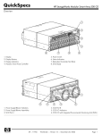
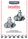
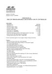
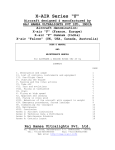
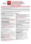
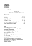
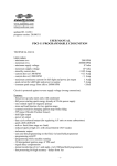
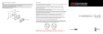
1
PROCEDURE NOTES
SUZUKI DL650
THROTTLE-BODY SYNCHRONISATION
1.
INTRODUCTION
The DL650 has two throttle bodies, one for each cylinder. These throttle bodies meter the air that is
delivered to each cylinder for fuel combustion. To ensure smooth operation of the bike’s engine, these
throttle bodies must be synchronised so that each cylinder receives the same amount of combustion
air for each power stroke.
This document provides notes on the procedure for synchronising the throttle bodies on the K4 to K6
DL650. These notes may also be suitable for later models. Synchronising the throttle bodies requires
the use of a manometer (vacuum pressure measuring device). There are many different types of
manometers available for this procedure and each have their own way of being used. This file does
not cover “how to use your manometer”. To perform this procedure properly, you must thoroughly
understand how to use your manometer.
Note: 1.
2.
2.
This procedure is not for those who are “mechanically challenged”. If you are, please
have this work done by a suitably experienced person. Fully read these instructions
before you start and make sure you understand everything.
It is recommended that you read the Tips & Suggestions at the end of these notes.
TIME & PERSONS
The procedure normally requires only one person and should take 0.5 (if extension tubes have been
fitted) to 2.5 hours. Depending on the manometer you use, your may require an additional person to
read the manometer while the other person makes the necessary adjustments.
3.
TOOLS
The tools and equipment you will need to perform this modification are-
4.
ITEM
REMARKS
Suzuki “Precision” Took Kit
This should have come with your bike. You will find it
under the bike’s seat.
Manometer, suitable for balancing
carburettors/throttle bodies (the DL650
throttle body vacuum pressure is between
14cm and 18cm of Hg)
Available from most good auto shops or you can
make your ownhttp://www.powerchutes.com/manometer.asp
Offset (bent) needle-nose pliers
At lease 200mm (8”)
Short (stubby) No. 2 crosshead (Phillips)
screwdriver
As short as possible.
DL650 Owners Manual
This should have come with your bike.
MATERIALS
The following materials are optional for performing this procedure.
ITEM
REMARKS
2 x 150mm (6”) automotive vacuum tube
Between 3mm to 5mm internal diameter (4mm
preferred). Available from most good auto shops
2 x connector pieces for 4mm diameter
vacuum tube
Available from most good auto shops
1 x small tube blue Loctite 243 (or similar)
A must for all bolted connections on the bike
Prepared by RBS_Cairns of the Yahoo! DL650 group
Suggested improvements to this document should be directed to the author at [email protected]
2
5.
PREPARATION
The bike’s Suzuki service manual calls for the bike’s air box to be removed before synchronising the
throttle bodies. From experience, this has not been found necessary, although it does give easier
access to the throttle body take-off pipes for the manometer. Many believe the effort is not worth it.
For these notes, the air box is not removed.
It is recommend (but not mandatory) that you fit new spark plugs and a clean air filter (if air box is left
in place) to the bike before proceeding with the throttle body synchronisation. See the Owners Manual
for fitting these items.
•
Remove the bike’s seat (see Owners Manual).
•
Remove the left-hand and right-hand black plastic side covers (see Owners Manual).
•
Raise the fuel tank (see Owners Manual) and support on its prop.
Note:
•
To remove the black plastic “press studs” use the smallest hex key in the tool kit to
press in the centre pin of the stud one click (about 2mm). You should then be able to
pull the stud (with pin) straight out. Be careful not to loose the pin.
Disconnect the IAP sensor hose from its connection on the air box (see fig. 1).
Figure 1
IAP Sensor Hose under Tank (lkg to left)
•
Remove IAP sensor vacuum damper from its metal support bracket (see Fig. 2). This is done
by pushing the vacuum damper and supporting rubber towards the rear.
•
Move the IAP sensor vacuum damper and hose forward so that it does not interfere with
access to the rear throttle body.
Prepared by RBS_Cairns of the Yahoo! DL650 group
Suggested improvements to this document should be directed to the author at [email protected]
3
Figure 2
IAP Sensor Vacuum Damper (lkg to rear, up and to left)
6.
CONNECTING THE MANOMETER
The manometer is connected to the vacuum takeoff points on the forward and rear throttle bodies.
There is one vacuum takeoff point on the forward throttle body (see Fig. 3) and two vacuum takeoff
points on the rear throttle body (see Fig. 4).
Figure 3
Forward Throttle Body Vacuum Takeoff Point (lkg to left)
Prepared by RBS_Cairns of the Yahoo! DL650 group
Suggested improvements to this document should be directed to the author at [email protected]
4
Figure 4
Rear Throttle Body Vacuum Takeoff Points (lkg to rear and left)
Two takeoff points on the rear throttle body are provided so that one can be used to power an
accessory (automatic chain oiler, cruise control, etc.) and the other can be used to synchronise the
throttle bodies. For throttle body synchronisation, either of the two rear throttle body vacuum takeoff
points can be used.
To attach a manometer tube, remove the black rubber cap and retaining spring from the appropriate
takeoff point. Then just push the manometer tube onto the takeoff point. You may find the bent
needle-nose pliers handy in removing the retaining springs.
Be careful not to loose the black rubber caps and their retaining springs.
It is not easy to get access to the vacuum takeoff points, however it can be done. To make the job
easier next (and this) time, see Tips & Suggestions at the end of this document.
7.
Note: 1.
The best fitting manometer tube has an internal diameter of 4mm, although 3mm or
5mm may be used.
2.
Always replace the black rubber cap and retaining spring onto the vacuum takeoff
point whenever the manometer tube is removed. There throttle bodies should never
be open to the atmosphere when the engine is running.
BALANCING THE THROTTLE BODIES
You are now ready to balance the throttle bodies.
Note:
Reconnect the IAP sensor hose onto its connection on the air box. The bike’s engine should
not be run with this hose disconnected. For throttle body synchronisation it is not necessary to
refit the IAP sensor vacuum damper back onto its support bracket.
•
Start the bike’s engine and allow it to idle until the temperature gauge shows three bars.
•
With the engine idling (i.e. throttle fully closed) adjust the throttle stop screw (see Owners
Manual – Idel Speed) until the engine speed is at “fast idle”, about 1,300rpm to 1,400rpm.
•
Note the reading(s) on your manometer.
Prepared by RBS_Cairns of the Yahoo! DL650 group
Suggested improvements to this document should be directed to the author at [email protected]
5
•
Using the short crosshead screwdriver, adjust the rear throttle body synchronisation screw.
The screw is found under the fuel tank on the right-hand side of the rear throttle body (see
Fig. 5). The screw may be very hard to turn. Just a little movement of this screw can greatly
affect the manometer reading(s).
Figure 5
TB Synchronising Screw under Tank (lkg forward and to left)
(Courtesy of an anonymous member of the Yahoo! DL560 group.)
•
After turning the screw a little, give the throttle a short “blip” and then allow everything to settle
down again before checking your manometer reading(s).
•
Keep on adjusting the synchronising screw (with throttle “blips”) until you have the throttle
bodies balance as close as your manometer will allow. Balanced means that they both have
equal vacuum pressure.
Your throttle bodies are now synchronised. You may like to dab a small amount of nail polish on
the screw to help keep it from moving with vibration.
8.
PUTTING IT ALL BACK TOGETHER
You are now ready to refit all the parts your removed in the preparation. This is done in the reverse
order by refitting •
Of course, you have removed the manometer tube(s) and replaced the black rubber caps
(including the retaining springs) onto the vacuum takeoff points.
•
Refit the IAP sensor vacuum damper onto its metal support bracket. This is not easy,
however with perseverance it will push back on.
•
Reconnect the IAP sensor hose to its connection on the air box.
•
Lower the fuel tank and secure it in place (see Owners Manual).
Note:
To refit the black plastic “press studs”, press the pin from the pointed end through the
“press stud” so that the pin’s head protrudes about 3mm past the head of the “press
stud”. The “press stud”/pin assembly is then inserted into the hole in the fairing and
the pin is pressed flush with the “press stud” head.
•
Refit the left-hand and right-hand black plastic side covers (see Owners Manual).
•
Refit the bike’s seat (see Owners Manual).
Prepared by RBS_Cairns of the Yahoo! DL650 group
Suggested improvements to this document should be directed to the author at [email protected]
6
9.
TIPS & SUGGESTIONS
Users of these procedure notes have provided the following tips and suggestions.
9.1
EXTENSION TUBES
The hardest part about this procedure is fitting the manometer tube to the throttle body
vacuum takeoff points. To make this easier, vacuum hose extension pieces can be fitted to
the relevant vacuum takeoff points. These hoses are then routed to the right-hand side of the
bike for attaching the manometer tube. The procedure is•
Remove the black rubber cap and retaining spring from the forward throttle body
vacuum takeoff point.
•
Fit a piece of 4mm internal diameter vacuum tube about 150mm long to the forward
throttle body vacuum takeoff point, securing it with the retaining spring that was with
the associated black rubber cap.
•
Route the vacuum tube to the right-hand side of the bike taking care that it is isolated
from any hot surface and will not chafe. Cut the tube to a suitable length if needed.
•
Fit a suitable vacuum tube connector piece to the free end of the tube.
•
Fit the associated black rubber cap to the open end of the connector piece.
•
Tuck the extension tube arrangement out of the way, again ensuring that it is isolated
from any hot surface and will not chafe.
•
Repeat the above procedure with the rear throttle body vacuum takeoff point.
To connect the manometer with these extension pieces fitted, you only have to remove the
black rubber cap from the end of the extension piece and attach the manometer tube.
9.2
MERCURY (Hg)
For those of you who are mathematically inclined and wish to convert mm of Hg to mm of
another liquid, mercury (Hg) has the following densities:
Temperature
(°C)
Mass
(g/ml)
0
13.60
10
13.58
15
13.57
20
13.56
25
13.55
30
13.53
35
13.52
If you use a liquid manometer that has a liquid other than mercury (Hg) and you know the
mass in g/ml of you manometer’s liquid, you can convert your manometer’s reading to mm of
mercury by DIVIDING your manometer’s reading in mm by-
Mass of Hg
Mass of Your Manometer' s Liquid
Prepared by RBS_Cairns of the Yahoo! DL650 group
Suggested improvements to this document should be directed to the author at [email protected]