1
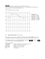
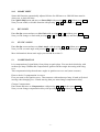
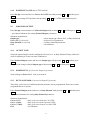
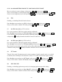
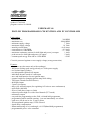
www.zeeltronic.com
[email protected]
updated 17.09.2009
program version: 01.080909
USER MANUAL
PDCI-20V PROGRAMMABLE CDI IGNITION AND PV CONTROLLER
Limit values:
- minimum revs
- maximum revs
- minimum supply voltage
- maximum supply voltage
- stand-by current draw
- current draw at 1300 RPM
- current draw at 12000 RPM
- maximum continuous current for shift light and power jet output
- peak current for shift light and power jet output
- constant spark energy from idle to 13000 RPM
200 RPM
20000 RPM
7 Volts
18 Volts
< 0.09 Amp
< 0.3 Amp
< 1.7 Amp
1 Amp
5 Amp
>35mJ
Circuit is protected against reverse supply voltage (wrong connection).
Features:
- fast power-up (also starts only with condenser)
- full power starting spark energy already at 7Volts power supply
- two isolated input (pickup)
- two independent ignition coil outputs
- individual advance/retard of each output
- store and load function for two ignition maps
- external switch for changing ignition map while riding
- TPS input (Throttle Position Sensor)
- shift light output
- 2 power jet outputs
- duty cycle solenoid output (for regulating A/F ratio on some carburettors)
- quick shift (shift kill)
- soft rev limit (three stage rev limit)
- reduced spark at high revs with closed throttle (TCT mode)
- tachometer output
- easy and fast programming on the field, via hand held programmer
- programming while machine running - you can immediately see effects
- each curve can be set in 4 to 12 curve points
- 3D interpolated ignition map, if TPS selected
- signal delay compensation
- instant monitoring of rev's and angle, via LCD(hand held programmer)
- programmable power valve actuation
-1-
- store and load function for 5 PV curves
- external switch for changing PV curve while riding
- programmable PV deviation
- programmable max close and max open positions
- self PV test on power-up
- PV error detecting (position sensor failure, servo motor failure)
- fast processing for high accuracy - delays from 1us
- timing calculation for every 1 RPM change (1000, 1002, .. , 9805, 9806, ...)
Very important!
Resistor spark plugs must be used, because they produce less electromagnetic disturbances.
Danger of electric shock!
Avoid connecting PDCI to 12V power supply, before connecting it to ignition coil. High voltage
is generated and touching free wires can cause electric shock, or damage the unit.
1.
HOW TO ENTER MENU
PDCI must be connected to power supply. Connect programmer to PDCI and wait few seconds
for activation of programmer and then press enter. With pressing + or - you can move
through menu and with pressing enter you can choose.
You can exit menu with choosing Exit.
2.
MENU ORGANISATION
Set Ign.
Set PV
Exit
2.1.
- set ignition parameters submenu
- set PV parameters submenu
SET IGNITION PARAMETERS SUBMENU
Load Ign. Map
Save Ign. Map
Set Ignition Map
Advance
Advance 1
Advance 2
Gear Shift Light
Quick Shift
Rev Limit
Static Angle
Compensation
Power Jet 1
Solenoid Output
TPS
TPS close [0%]
TPS open [100%]
- load (select) ignition map (from #1 to #2)
- save new ignition map (from #1 to #2)
- ignition map parameters submenu
- advance/retard whole ignition map on both ignition coil outputs
- advance/retard ignition coil output 1
- advance/retard ignition coil output 2
- shift light
- quick shift settings
- rev limit
- static angle (stator position)
- signal delay compensation (from pickup to spark plug)
- power jet 1
- solenoid output settings (power jet 2, or duty solenoid)
- enable, or disable TPS
- calibrating TPS close position
- calibrating TPS open position
-2-
TCT mode
Ign. Map SW
Pulses Per Rev
Exit
2.2.
SET PV PARAMETERS SUBMENU
Load PV Curve
Save PV Curve
Set PV Curve
Deviation +Close Position
Open Position
PV Test
Power-up Test
PV Curve SW
Exit
3.
- reduced spark at high revs with closed throttle
- activating/deactivating external switch for selecting ignition map
- number pulses per revolution from pickup
- load (select) PV curve (from #1 to #5)
- save new PV curve (from #1 to #5)
- PV curve parameters submenu
- deviation of PV position
- max close PV position
- max open PV position
- PV position test
- enable, or disable test cycle at power-up
- activating/deactivating external switch for selecting PV curve
LOAD IGN. MAP
Enter Set Ign. menu and move to Load Ign. Map with pressing + or - and then press enter .
Now you can select number of saved ignition map, with pressing + or - and then press enter .
4.
SAVE IGN. MAP
Enter Set Ign. menu and move to Save Ign. Map with pressing + or - and then press enter .
Now you can select number to which you want to save your ignition map, with pressing + or and then press enter .
5.
SET IGNITION MAP (if TPS disabled)
Enter Set Ign. menu and move to Set Ignition Map with pressing + or - and then press enter.
...you entered submenu for setting ignition map.
Submenu organisation:
Nr. of Points
- number of ignition curve points (from 4 to 12)
1)
- first ignition curve point
2)
- second ignition curve point
...
...
...
...
Exit
- exit submenu
-3-
Important!
To avoid wrong processing, don't make unreasonable curve course.
Every time you make any changes to ignition curve, it is automatically saved to number #0.
Later you can save it to any other number #1 or #2.
Curve Example with six curve points:
5.1.
SET IGNITION MAP (if TPS enabled)
Three ignition curves must be programmed for different TPS positions. PDCI does not only
switch between ignition curves, but also interpolate 3D map for all TPS positions above 33%.
Enter Set Ign. menu and move to Set Ignition Map with pressing + or - and then press enter.
...you entered submenu for selecting ignition curve.
Submenu organisation:
Nr. of Points
- number of ignition curve points (from 4 to 10)
Curve 0-33%
- ignition curve from 0 to 33% TPS
Curve 66%
- ignition curve for 66% TPS
Curve 100%
- ignition curve for 100% TPS
Exit
- exit submenu
-4-
Important!
To avoid wrong processing, don't make unreasonable curve course.
Every time you make any changes to ignition curve, it is automatically saved to number #0.
Later you can save it to any other number #1 or #2.
Ignition Map Example:
5.2.
Change NUMBER OF IGNITION CURVE POINTS
Move to Nr. of Points with pressing + or - and then press enter .
Now you can select number of ignition points, with pressing + or - and then press enter .
5.3.
Change PARAMETERS OF IGNITION CURVE POINT
Move to point you want to change, with pressing + or - and then press enter .
Now you can change rev point with pressing + or - (in 100 rpm steps) and then press enter .
Now you can change advance angle with pressing + or - (in 0.1deg steps) and then press
enter .
6.
ADVANCE
With this setting is possible to advance, or retard whole ignition map on both ignition coil
outputs. When setting is positive, then ignition map is advanced and when setting is negative,
than ignition map is retarded. Ignition map is unchanged, with setting 0.0deg.
Enter menu and move to Advance, with pressing + or - and then press enter .
Now you can set advance with pressing + or - (in 0.1deg steps) and then press enter .
-5-
7.
ADVANCE 1
With this setting is possible to advance, or retard ignition map only on ignition coil output 1.
When setting is positive, then ignition map is advanced and when setting is negative than,
ignition map is retarded. Ignition map is unchanged, with setting 0.0deg.
Enter menu and move to Advance, with pressing + or - and then press enter .
Now you can set advance with pressing + or - (in 0.1deg steps) and then press enter .
8.
ADVANCE 2
With this setting is possible to advance, or retard ignition map only on ignition coil output 2.
When setting is positive then, ignition map is advanced and when setting is negative than,
ignition map is retarded. Ignition map is unchanged, with setting 0.0deg.
Enter menu and move to Advance, with pressing + or - and then press enter .
Now you can set advance with pressing + or - (in 0.1deg steps) and then press enter .
9.
GEAR SHIFT LIGHT
Enter Set Ign. menu and move to Gear Shift Light with pressing + or - and then press enter .
Now you can change rev point with pressing + or - (in 100 rpm steps) and then press enter .
10.
QUICK SHIFT
Enter Set Ign. menu and move to Quick Shift with pressing + or - and then press enter .
...you entered submenu for quick shift settings.
Submenu organisation:
Shift Kill Time
- basic kill time
Smart Shift
- activating/deactivating automatic kill time for different revs
Exit
- exit submenu
10.1. SHIFT KILL TIME
Enter Quich Shift menu and move to Shift Kill Time with pressing + or - and then press
enter.
Now you can change kill time with pressing + or - (in 10 ms steps) and then press enter .
-6-
10.2. SMART SHIFT
Smart shift function automatically adjusts kill time for different revs. Shift kill time must be
always set, as basic kill time.
Enter Quich Shift menu and move to Smart Shift with pressing + or - and then press enter.
Now you can enable, or disable function with pressing + or - and then press enter .
11.
REV LIMIT
Enter Set Ign. menu and move to Rev Limit with pressing + or - and then press enter .
Now you can change rev limit with pressing + or - (in 100 rpm steps) and then press enter .
12.
STATIC ANGLE
Enter Set Ign. menu and move to Static Angle with pressing + or - and then press enter .
Now you can set static angle with pressing + or - (in 0.1deg steps) and then press enter .
More information's about static angle you can find in section 31.
13.
COMPENSATION
It is compensation of signal delay from pickup to spark plugs. You can check this delay with
stroboscope lamp. Without this compensation, ignition advance angle decreasing with rising
revs.
This compensation helps that advance angles in ignition curve are real (more accurate).
How to check, if compensation is correct:
First you must set flat ignition curve. Then measure with stroboscope lamp, if mark at flywheel
moving when changing revs. If mark moving then you must change compensation delay.
Change Compensation:
Enter menu and move to Compensation with pressing + or - and then press enter .
Now you can change compensation delay with pressing + or - and then press enter .
-7-
14.
POWER JET 1
Enter Set Ign. menu and move to Power Jet 1 with pressing + or - and then press enter .
...you entered submenu for setting Power Jet 1 parameters.
Submenu organisation:
Power Jet 1 ON RPM
Power Jet 1 OFF RPM
Power Jet 1 ON TPS (if TPS enabled)
Power Jet 1 OFF TPS (if TPS enabled)
Exit
- revs for activating power jet 1
- revs for deactivating power jet 1
- throttle position for activating power jet 1
- throttle position for deactivating power jet 1
- exit submenu
Example:
Power jet 1 ON (RPM) = 8000rpm
Power jet 1 OFF (RPM) = 10000rpm
Power jet 1 ON (TPS) = 70%TPS
power jet 1 OFF (TPS) = 90%TPS
Power jet is switched on when revs are between 8000-10000rpm and throttle position is between
70-90%, otherwise power jet is switched off.
14.1. POWER JET 1 ON RPM
Enter Set Ign. menu and move to Power Jet 1 ON RPM with pressing + or - and then press
enter .
Now you can change Power Jet 1 ON RPM with pressing + or - (in 100 rpm steps) and then
press enter .
14.2. POWER JET 1 OFF RPM
Enter Set Ign. menu and move to Power Jet 1 OFF RPM with pressing + or - and then press
enter .
Now you can change Power Jet 1 OFF RPM with pressing + or - (in 100 rpm steps) and then
press enter .
14.3. POWER JET 1 ON TPS (if TPS enabled)
Enter Set Ign. menu and move to Power Jet 1 ON TPS with pressing + or - and then press
enter .
Now you can change TPS position with pressing + or - (in 1%TPS steps) and then press
enter .
-8-
14.4. POWER JET 1 OFF TPS (if TPS enabled)
Enter Set Ign. menu and move to Power Jet 1 OFF TPS with pressing + or - and then press
enter .
Now you can change TPS position with pressing + or - (in 1%TPS steps) and then press
enter .
15.
SOLENOID OUTPUT
Enter Set Ign. menu and move to Solenoid Output with pressing + or - and then press enter .
...you entered submenu for setting Solenoid Output parameters.
Submenu organisation:
Output type
Power Jet 2 (if selected)
Duty Solenoid (if selected)
Exit
- select output type (Power Jet 2, or Duty Solenoid)
- set Power Jet 2 parameters
- set Duty Solenoid parameters
- exit submenu
15.1. OUTPUT TYPE
Solenoid output function can be configured as Power Jet 2, or Duty Solenoid. Duty solenoid is
used for adjusting A/F ratio on some carburettors.
Enter Solenoid Output. menu and move to Output type with pressing + or - and then press
enter .
Now you can change solenoid Output type with pressing + or - and then press enter .
15.2. POWER JET 2 (if selected in Output Type menu)
Same settings as Power Jet 1...look at section 14.
15.3. DUTY SOLENOID (if selected in Output Type menu)
Three duty cycle curves for different throttle positions can be programmed. Each curve can be
programmed in 8 rev points.
Enter Solenoid Output menu and move to Duty Solenoid with pressing + or - and then press
enter .
...you enterd submenu for setting Duty Solenoid parameters.
Submenu organisation:
Curve 0-33%
- duty cycle curve from 0 to 33% TPS
Curve 34-66%
- duty cycle curve from 34 to 66% TPS
Curve 67-100%
- duty cycle curve from 67 to 100% TPS
Exit
- exit submenu
-9-
15.3.1 Set PARAMETERS FOR DUTY SOLENOID CURVE POINT
Move to point you want to change, with pressing + or - and then press enter .
Now you can change rev point with pressing + or - (in 100 rpm steps) and then press enter .
Now you can change duty cycle with pressing + or - (in 1% steps) and then press enter .
16.
TPS
Enabling, or disabling Throttle Position Sensor.
Enter Set Ign. menu and move to TPS with pressing + or - and then press enter .
Now you can enable or disable TPS with pressing + or - and then press enter .
17.
Set TPS close [0%] (if TPS enabled)
For correct operation, TPS close position must be calibrated!
Enter Set Ign. menu and move to TPS close [0%] with pressing + or - and then press enter.
Leave throttle at close position and confirm calibrating with pressing enter , or exit calibration
with pressing - . Displayed number should be between 0 and 500.
18.
Set TPS open [100%] (if TPS enabled)
For correct operation, TPS open position must be calibrated!
Enter Set Ign. menu and move to TPS open [100%] with pressing + or - and then press enter.
Move throttle to maximum open position and confirm calibrating with pressing enter , or exit
calibration with pressing -. Displayed number should be between 500 and 1010.
19.
TCT mode
Throttle Close spark Termination mode, reduces number of sparks (spark is active every third
revolution) above 8000rpm, when throttle is closed. TCT mode ensure better engine cooling.
Enter Set Ign. menu and move to TCT mode with pressing + or - and then press enter .
Now you can enable or disable TCT mode with pressing + or - and then press enter .
20.
IGN. MAP SW
Enabling, or disabling ignition map switch, for changing ignition maps while riding.
Enter Set Ign. menu and move to Ign. Map SW with pressing + or - and then press enter .
Now you can enable or disable external switch with pressing + or - and then press enter .
- 10 -
21.
PULSES PER REV
It is number of pulses per rev from pickup coil and is important for correct rev reading. Setting is
2 for all twins with wasted spark ignition system.
Enter Set Ign. menu and move to Pulses Per Rev with pressing + or - and then press enter.
Now you can change nr. of pulses per rev with pressing + or - and then press enter .
22.
LOAD PV CURVE
Enter Set PV menu and move to Load PV Curve with pressing + or - and then press enter.
Now you can select number of PV curve with pressing + or - and then press enter .
23.
SAVE PV CURVE
Enter Set PV menu and move to Save PV Curve with pressing + or - and then press enter.
Now you can select number to save your PV curve, with pressing + or - and then press enter .
24.
Set PV Curve
Enter Set PV menu and move to Set PV Curve with pressing + or - and then press enter .
...you entered submenu for setting PV curve.
Submenu organisation:
Nr. of Points
- number of PV curve points (from 2 to 8)
1)
- first valve position point
2)
- second valve position point
...
...
...
...
Exit
- exit submenu
Important!
To avoid wrong processing, don't make unreasonable curve course.
Every time you make any changes to PV curve, it is automatically saved to number #0. Later you
can save it to any other number from #1 to #5.
24.1. Change Number of Curve Points
Move to Nr. of Points with pressing + or - and then press enter .
Now you can select number of curve points, with pressing + or - and then press enter .
- 11 -
24.2. Change Parameters of PV Curve Points
Move to point you want to change, with pressing + or - and then press enter .
Now you can change rev point with pressing + or - (in 100 rpm steps) and then press enter .
Now you can change PV position from 0% to 100%, with pressing + or - (in 1% steps) and
then press enter .
25.
Set Deviation
Enter Set PV menu and move to Deviation with pressing + or - and then press enter .
Now you can change deviation from 2% to 20% with pressing + or - (in 1% steps) and then
press enter .
Deviation means how accurate valve is moved to calculated position. If deviation is too low then
servo motor won't be stabile – it will always search for calculated position in small movements.
Default setting is +-5% and should meet in most cases.
26.
CLOSE POSITION
Max close position must be calibrated after installation. Max close position is when curve is set
to 0%. Close position can be moved to any desired position.
Enter Set PV menu and move to Close Position with pressing + or - and then press enter .
Now you can set close position with pressing + or - and then press enter .
27.
OPEN POSITION
Max open position must be calibrated after installation. Max open position is when curve is set to
100%. Open position can be moved to any desired position.
Enter Set PV menu and move to Open Position with pressing + or - and then press enter .
Now you can set open position with pressing + or - and then press enter .
Max open position is when curve is set to 100%. This open position can be moved to any desired
position.
28.
PV Test
PV test can be used for testing or measuring valve position. Valve can be moved to any position
from 0% to 100%, without engine running.
Enter Set PV menu and move to PV Test with pressing + or - and then press enter .
Now you can set valve position with pressing + or - and then press enter .
- 12 -
29.
POWER-UP Test
Enabling or disabling test cycle of PV servo at power-up.
Enter Set PV menu and move to Power-up Test with pressing + or - and then press enter .
Now you can enable or disable power-up test with pressing + or - and then press enter .
30.
PV CURVE SW
Enabling, or disabling PV curve switch for changing PV curves while riding.
Enter Set PV menu and move to PV Curve SW with pressing + or - and then press enter .
Now you can enable, or disable PV Curve switch with pressing + or - and then press enter .
31.
MECHANICAL SETTINGS (Static Angle)
Static Angle is ignition advance angle, set with stator (generator).
Measure this angle with dial gauge. This measured Static Angle is your maximum advance
angle you can set with PDCI.
Calculating mm to deg or vice versa:
32.
MONITORING
Connect programmer to PDCI and wait few seconds for activation of programmer. Fist
information displayed on the programmer is software version.
With programmer you can watch revs, calculated advance ignition angle, TPS
position...depends on setting in the menu.
Information!
You can connect or disconnect PDCI unit from programmer any time you want, without any
harm. It is not important, if motor running or not and if power supply is connected or not.
Important!
Do not use too much force when connecting or disconnecting programmer unit!
- 13 -
33.
ERROR REPORTS
PVerr 1 – position sensor error or servo motor disconnected
PVerr 2 – servo motor error (short connection)
- 14 -