1
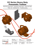
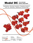
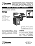
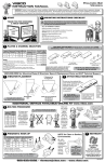
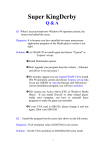
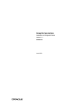
BIG BERTHA
vibco
instruction manual
DUMP BODY VIBRATORS
WARNING: Failure to read and follow these installation instructions and safety precautions could result in personal injury, equipment damage,
shortened service life or unsatisfactory equipment performance. All information in this document is vital to the proper installation and operation of
the equipment. It is important that all personnel who will be coming in contact with this product thoroughly read and understand this manual.
start
1
mounting instructions checklist
2
THANK YOU FOR
CHOOSING A VIBCO
The warranty is void if vibrator is not properly installed. During
installation follow and check off the following steps and your
vibrator should provide you with years of trouble-free service.
BIG BERTHA
TM
DUMPBODY
VIBRATOR!
BIG
a
ith
BERTHA
s w plate!
e
com nting
u
mo
Y
ANT
R
WAR
oDetermine vibrator placement on dump body.
oSelect thickness of mounting plate.
oDetermine length of channel iron
oSTITCH weld mounting plate to channel iron.
oSTITCH weld channel iron to dump body.
oPlace vibrator on mounting plate.
Check the mounting plate for warping. Secure firmly.
oInstall safety chain or wire.
oConnect electrical wiring.
oFILL OUT WARRANTY CARD!!!!
DON’T FORGET
TO MAIL IN YOUR
WARRANTY CARD!
ADDITIONAL DETAILS AVAILABLE ONLINE AT www.vibco.com
vibrator placement & force settings
3
Place vibrator underneath body
a 1/4-1/3 length from front &
centered between sills or
main beams*.
Make sure vibrator clears
hydraulic tanks, gas tanks
etc., when the body is in
down position**.
¢
1/4
to
CUBIC
BODY
BIG BERTHA
YARDAGE LENGTH
2-8
10 - 12
DC-3500-1500
5 - 10
13 - 14
DC-3500-2500
8 - 16
15 - 16
DC-3500-2700
15 - 30
17 - 40
DC-3500
3/4”
mounting plate
provided with
Big Bertha!
Channel iron should be 6”
wide with custom lengths to fit
the specific dump body style.
Reference panel 5 to identify
which mounting style you have
to determine channel length.
Reduced force kits avaiable fom VIBCO.
1/3
* Vibrator CAN be mounted on the side of dump body.
Call or go online
for proper side mount specifications.
** Handle can be removed if needed. Removing it will not effect
performance. Or exchange for handless model DC-3500-S.
5
plates & channel selection
4
mounting style
FOR SMALLER
DUMP BODIES
For aluminum or heated bodies and other types of mounts call VIBCO 401-539-2392
FOR DUMP BODIES
WITH CROSS MEMBERS
FOR CROSS MEMBER LESS
DUMP BODIES
(unheated)
Stitch weld
a 4 in.
channel iron,
inverted, over a
minimum of 3 to
5 cross members
& weld mounting
plate to middle of
channel iron. Be sure unit is directly over
intersection of stiffener & channel iron.
STITCH
weld
a 6 in.
channel
between
cross
members
& to body
(skip weld
to body) & weld mounting plate to
middle of channel iron.
Plate &
Channel
Combo
The success of Big Bertha™
relies on proper mounting with
a plate & channel combo.
Drill 13/16” holes in channel aligned
with tapped holes in mounting
plate. Stitch weld mounting plate to
underside of channel iron starting 1/2”
in from the ends leaving approximately
2” between welds. STITCH weld 6 in.
channel 4’ to 6’ long centered on the
dumpbody 1/4 of the body length from
the front of the
dump body.
stitch weld
6
DO NOT MOUNT
VIBRATOR DIRECTLY
TO SURFACE OF DUMP BODY!!!
Always use mounting plate & channel
STITCH WELDS SHOULD
BE 3” - 6” LONG LEAVING
3” (7.5cm) BETWEEN
EACH WELD
3”
1”
END VIEW
STITCH WELDS
SHOULD START
& STOP 1” (2.5cm)
FROM BOTH ENDS
OF CHANNEL TO
PREVENT CRACKING
800-633-0032 for Mounting Plates & Brackets, Spare & Replacement Parts and 24/7 Technical Support
7
bolting procedure
Use channel iron, NOT angle iron to mount!
A loose vibrator can cause damage
to the truck body & may also get
electrically overloaded, which could
cause motor burnout.
CAUTION:
A warped mounting plate
can cause damage to the
vibrator housing. When
mounting, secure vibrator
with one bolt (use Loctite
242 or equal) & lock washer.
Shim opposite foot
(overshim slightly), then
tighten the other bolt.
!
Be sure surface is smooth,
flat & free of any debris.
9
electrical installation
Push Button Switch
To Ignition Switch
Controlled Power
Source (Fused)
16 AWG Wire
CB12V
Circuit Breaker
Solenoid
BAT
B
DC-3500
Vibrator
16 AWG Wire
110 in-lbs
Power Stud
Nut
4 AWG Wire
Mount one end to the vibrator
and the other to the hopper or bin
above the vibrator
NEVER ATTACH TO THE
MOUNTING PLATE!
safety
cable
install
push button
on panel
If vibrator operates
more than 30 seconds,
circuit breaker will open & shut
it down. It will automatically
reset in approx. 2 minutes.
battery
positive
terminal
BIG BERTHA
circuit
breaker
4 AWG Wire*
* For lengths exceeding
50 ft. use 2 AWG wire.
Using a DC volt meter, take an voltage reading while
vibrator is running. Should read 11.5 volts MINIMUM.
restraint
AUX
Grounds
Through Foot
Grounds
Through Foot
8
ALWAYS INSTALL
SAFETY
CABLE or CHAIN
TORQUE =
260 ft-lbs.
Make sure the vibrator is secured tightly.
Retighten after the first 10 -15 minutes
of operation & check them periodically to
maintain proper tightness.
DO NOT run
unit unless
bolted down!
Grounding strap
supplied w/ wiring kit
Check those
bolts for
tightness!
+
Battery
12 Volt DC
Ground
solenoid
switch
NOTE!
WARRANTY VOID
IF CIRCUIT
BREAKER
NOT INSTALLED!
power
cable
Master & Pilot Circuit Required (wiring kit incl ).
800-633-0032 • [email protected] • www.vibco.com
REV198-15
BIG BERTHA
vibco
instruction manual
DUMP BODY VIBRATORS
WARNING: Failure to read and follow these installation instructions and safety precautions could result in personal injury, equipment damage,
shortened service life or unsatisfactory equipment performance. All information in this document is vital to the proper installation and operation of
the equipment. It is important that all personnel who will be coming in contact with this product thoroughly read and understand this manual.
10
Duty cycle & operation
Model DC-3500 is rated for:
Best operation is short 3-5 second ON cycles
allowing the unit to spin down and go through a
range of frequency. Cycling the ON/OFF times
will aid in faster clean out of the dumpbody.
Timers are avaiable thru VIBCO to automate this
system.
INTERMITTENT DUTY ONLY
MAXIMUM RUN TIME = 30 sec.
(with MINIMUM one (1) minute off time)
DO NOT EXCEED
20 MIN RUN TIME IN ANY 60 MIN PERIOD
13
Troubleshooting
1) Vibrator doesn’t start or runs and stops.
- Make sure vibrator is getting power. Check fuses and make sure all connections are properly secured.
- Make sure the vibrator is properly grounded to the frame. If vibrator is not mounted to main frame, such as on a pivoted truck body, make sure body is grounded to main frame.
- The vibrator is designed to ground through the foot. For more positive grounding, use the grounding strap provided in the wiring kit.
- Make sure push button or on/off switch and solenoid are working. If damaged or non functioning, replace.
- Some newer trucks have additional circuit breakers wired in for accessories. Check for hidden circuit breakers and make sure your power is direct to the battery terminal.
2) Vibrator is running slow (loss of RPM). I did a voltage test on the vibrator and it reads less than 11.5 volts:
- Was test done with truck engine running? If not, test again with engine running. If voltage is now above 11.5 volts, vibrator should be operated only when engine is running (or have
truck’s electrical system checked).
- If voltage is still below 11.5 volts, test voltage at battery. Battery voltage should be a minimum of 13 volts. If less than 13 volts, have truck’s electrical system checked.
- If battery voltage is 13 volts or higher, check power wire to vibrator. Wire gauge should be minimum of 4 AWG for lengths up to 50 ft.; 2 AWG for lengths of 51 ft. to 100 ft. NOTE:
power cables can deteriorate over time, losing their current carrying capacity.
- Check ground connection of vibrator — grounds through foot to dump body. A good ground is critical to proper vibrator operation. Make sure that bottom of vibrator feet and mounting
plate are clean bare metal, and corrosion free. If an adequate ground connection cannot be achieved through the foot, a separate grounding strap may need to be installed.
- Check the brushes and change if necessary. The life of brushes is approximately 1,000 hours. Brush life is dependent on the duty cycle.
3) An unusual sound (banging) coming from the vibrator.
- Check the vibrator mounting bolts for tightness. The vibrator could be loose.
- New installations may be too weak. Reinforce mount area immediately by adding stiffeners-angle iron or channel iron.
- Look for cracks in the housing, mounting angle iron or plates. Also look for fatigued or cracked welds. Repair and reinforce immediately.
ADDITIONAL DETAILS AVAILABLE ONLINE AT www.vibco.com
adjusting eccentrics On DC-3500ADJ*
To change eccentric settings:
1. Unscrew (2) 3/8-16 x 6-1/2 hex head bolts.
2. Remove dust cover.
3. Pull motor field away from armature assembly.
4. Unscrew 3/8-16 x 1-1/4 socket head bolts.
5. Remove cover by unscrewing (3) 10-24 x 3/8” screws & using longer
screws in (3) threaded holes in mounting cover, turn screws to draw
motor assembly out of housing
6. Loosen (2) 3/8-16 x 1/2 set screws on outer most eccentric and
adjust to desired output according to chart at right.
To reassemble:
1. Put eccentric & armature assembly back onto housing using 3/8-16 x
1-1/4 socket head bolts with disk locks.
2. Make sure motor shaft spins freely before reassembling. If it doesn’t,
tap front of the mounting cover until it does.
3. Put motor field back on armature, spreading brushes over
commutator. NOTE: be sure field pin lines up with of mounting cover
holes and terminal port is in center of feet of housing!
4. Put dust cover back on with (2) 3/8-16 x 6-1/2 hex head bolts &
tighten evenly to draw back into place.
Eccentric settings
Standard Factory Setting
3500 lbs.
for
Dump Body Lengths
17 - 40 ft.
2700 lbs. of force
for
Dump Body Lengths
15 - 16 ft.
2500 lbs. of force
for
Dump Body Lengths
13 - 14 ft.
1500 lbs. of force
Adjustable
Eccentric
Kit available
Gasket seals
and rubber
washers should
be used
for operation
in a wet
environment
for
Dump Body Lengths
up to 10 - 12 ft.
5
6
1
3
eccentrics are standard on
*theAdjustable
DC-3500ADJ - adjustable eccentric
kit may be purchaced separately.
2
NOTE:
use Loctite 242 or
equal when replacing
screws
4
VIBCO’s factory sets eccentrics to the proper
specifications for your dump body length.
For custom mounting
applications or any other questions:
800-633-0032
or
[email protected]
Warranty
All warranty claims must be submitted to VIBCO for approval prior to any repairs being done. Failure to do so will
void any and all warranty coverage. All repairs will be done
at the VIBCO factory.
Errors, Shortages & Complaints
Complaints concerning goods received or errors should be
made at once. Claims must be made within five days after
receipt of goods. Clerical errors are subject to correction.
Damage during shipping must be reported to the carrier,
not VIBCO.
Returning Parts **
Parts should not be returned to VIBCO without prior authorization. Call VIBCO’s customer service department
at 800-633-0032 (800-465-9709 in Canada) for a Return
Goods Authorization (RGA) number. A return authorization
will be emailed or faxed to you. Use this as your packing
slip. Return shipping must be prepaid. Material returned
may be subject to a 10% restocking fee. All returned
shipments should clearly display your name, address and
original invoice number to ensure proper credit.
** Orders for custom equipment built to customer’s specifications are not returnable.
Product Changes
VIBCO reserves the right to make changes in pattern,
design or materials when deemed necessary, without prior
notice or obligation to make corresponding changes in previous models. To be sure of exact mounting dimensions,
it is recommended that you obtain a certified dimensional
drawing from the factory.
Ordering Spare Parts
Parts can be ordered through authorized distributors or
from VIBCO’s Spare Parts Department. The following data
should be provided when placing your spare parts order:
From label:
Model number of unit.
From spare parts list: Reference number, part number,
description & quantity required.
Shipping instructions: Specify shipping point and method
of shipping.
800-633-0032 • [email protected] • www.vibco.com
REV198-15