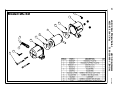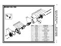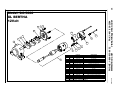
1
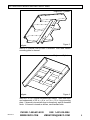
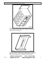
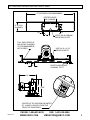
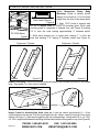
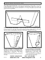
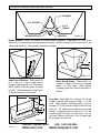
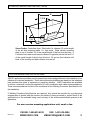
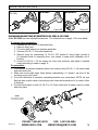
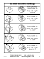
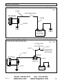
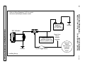
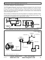
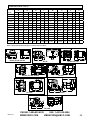
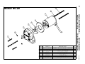
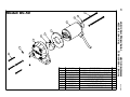
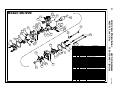
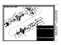
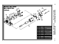
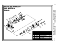
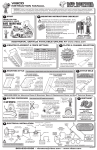
Model DC
12 & 24 Volt
Battery Operated
Specifications • Mounting Instructions • Operating Instructions
Parts List • Dimensions • Maintenance •Technical Data
HQ & Factory:
75 Stilson Road
Wyoming, RI 02898
Canada:
2215 Dunwin Drive
Mississauga, ONT L5L 1X1
E-mail: [email protected]
Phone: 800 633-0032
(401) 539-2392
Fax: (401) 539-2584
E-mail: [email protected]
Phone: 800 465-9709
(905) 828-4191
Fax: (905) 828-5015
WARNING: Failure to read and follow these installation instructions and safety
precautions could result in personal injury, equipment damage, shortened service
life or unsatisfactory equipment performance. All information in this document is
vital to the proper installation and operation of the equipment. It is important that
all personnel who will be coming in contact with this product thoroughly read and
understand this manual.
Thank you for choosing VIBCO, Inc. for your vibration needs. You are now the owner of the
finest 12 volt DC battery operated vibrator available today backed by complete manufacturer
confidence in its quality and dependability. For reference please complete the information below
about your new VIBCO vibrator.
Model Number:
____________________
Serial Number:
____________________
Date of Purchase: ____________________
TABLE OF CONTENTS
Warning Labels and Serial Number Tags.......................................................................................3
DC-3500 Mounting Instructions................................................................................................4-9
DC Mounting Instructions.........................................................................................................9-12
Operating Instructions.................................................................................................................13
Adjusting Eccentrics..............................................................................................................13-15
Electrical Installation...................................................................................................................16
Electrical Installation Procedure .................................................................................................17
Brush Kit Replacement...............................................................................................................17
Wiring Diagrams..........................................................................................................................18-20
Troubleshooting...................................................................................................................21
Technical Data and Dimensions...................................................................................................22-23
Parts Lists and Breakdown
DC-20....................................................................................................24
DC-50........................................................................................................25
DC-60............................................................................................................26
DC-100....................................................................................................27
DC-200................................................................................................28
DC-300................................................................................................29
DC-450T................................................................................................30
DC-500................................................................................................31-32
DC-700..................................................................................................33
DC-900................................................................................................34
DC-1600................................................................................................35
DC-3500 12 & 24 Volt...................................................................................................36-37
DC-5000........................................................................................................38
Warranty and General Information..............................................................................................39
REV295-13
PHONE: 1-800-633-0032
FAX: 1-401-539-2584
WWW.VIBCO.COM
[email protected]
2
WARNING LABELS AND SERIAL NUMBER TAGS
IMPORTANT
WARNING
WARNING!
Do not operate with counterweight guards
removed. Whenever the covers are removed
make sure that the power is turned off and
locked so it cannot be turned on accidentally.
Location: On body of vibrator.
Do not operate with
counterweight guards
removed.
No Opere Con El
Contrapest De
Protección Removido
Ne pas faire fonctionner
si les dispositifs de
protection de contrepoids
sont enlevés.
IMPORTANT
WARNING
WARNING!
Make sure ground connections are completed.
Before working on unit, disconnect electric
supply.
Location: Wrapped around end of cord.
Make sure ground
connections are completed.
Disconnect electric supply
before working on unit.
Asegurese Que La Conexion
A Tierra Esta Hecha. Antes
De Abrur La Unidad
Desconecte La Energia
Eléctrica
S´assurer se les mises à la
masse sont bien effectu `es
Avant de travailler sur
l`appareil, débrancher la
source d`alimentation
Please have the information on this tag
ready when ordering parts or contacting
the technical service department at VIBCO.
Location: On top of conduit box.
DC-3500: Sticker on round motor.
REV295-13
PHONE: 1-800-633-0032
FAX: 1-401-539-2584
WWW.VIBCO.COM
[email protected]
3
MOUNTING INSTRUCTIONS CHECKLIST
The warranty is void if vibrator is not properly installed. During installation follow and check off the
following steps and your vibrator should provide you with years of trouble-free service.
□ Determine the length of the channel iron.
□ Select thickness of vibrator mounting plate and method of mounting.
□ STITCH Weld mounting plate to channel iron.
□ Determine where vibrator should be placed on the bin.
□ STITCH Weld channel iron to bin.
□ Place vibrator on mounting plate. It is important that you check the
mounting plate for any warping. Secure vibrator firmly.
□ Install safety chain or wire.
□ Connect electrical wiring.
□ FILL OUT WARRANTY CARD!!!
Important Safety Instructions
When installing vibrator, make sure that the rotary motion of the vibrator is in the direction of flow (the
length of the vibrators body should be 90 degrees or perpendicular to the direction of flow). Secure
one end of vibrator to the mounting plate using one or two bolts (depending on the model). If mounting
plate is warped or bent due to welding, shim the opposite end of vibrator (over-shim slightly) and tighten
remaining mounting bolt(s) to 260 ft-lbs. Remove end cover on vibrator and spin shaft with finger, it
should spin freely - if not, re-shim vibrator (does not apply to DC-60, DC-500, or DC-3500). Retighten the
bolts after the first 10-15 minutes of running, then check them periodically for tightness. When mounting
the DC-3500 secure vibrator with one bolt (use Loctite 242 or equal), and lock washer. Shim opposite foot
(overshim slightly), then tighten other bolt.
WARPED
PLATE
WARPED
PLATE
Note: A loose vibrator can cause damage to the bin and may also get electrically overloaded, which
could cause motor burnout. Be sure to install a safety chain or cable to vibrator. Adhere to any other local,
state or federal safety codes that may apply.
For no weld, bolt on installations contact the technical service department at VIBCO
at 1-800- 633-0032.
REV295-13
PHONE: 1-800-633-0032
FAX: 1-401-539-2584
WWW.VIBCO.COM
[email protected]
4
DC-3500/5000 MOUNTING INSTRUCTIONS
Push-Button
On panel
Saftey
Cable
Battery
Positive
Terminal
Solenoid
Switch
Power
Cable
Figure 1
Flat Bed Dump Trucks and Tandem Trailers
The vibrator should be located underneath the body, preferably 1/4 the body length from the
front, or as close to this as possible, and centered between sills or main beams (see Figures 1 &
2). Check to make sure the vibrator clears hydraulic tanks, gas tanks etc., when the body is in
the down position. It is important to reinforce the truck body so it will be able to take the vibration
created without causing damage. For large dump body trucks, the easiest and most effective
way to mount the vibrator is to weld a 4 in. channel iron over at least three cross members. Weld
vibrator mounting plate onto the channel iron, positioning the mounting plate on the channel iron
over a stiffener (see Figure 3). For small dump body trucks, weld a 6 in. channel between cross
members and to body (skip weld to body), and weld the vibrator mounting plate to the middle
of the channel iron (see Figure 5). For aluminum body trucks, use an aluminum channel and
weld it over at least three cross members, and weld an aluminum vibrator mounting plate to the
middle of the channel iron, over the middle of a stiffener (see Figures 2 & 3). On front mounted
telescopic hoist bodies, locate vibrator just outside either one of the long members.
Figure 2
Weld sides and underneath channel to dump body stiffener. Place channel as close to the
doghouse as possible.
REV295-13
PHONE: 1-800-633-0032
FAX: 1-401-539-2584
WWW.VIBCO.COM
[email protected]
5
DC-3500/5000 MOUNTING INSTRUCTIONS
Doghouse / Cylinder
Tailgate
Figure 3
Weld 4 in. channel over at least 3 stiffeners. Then weld vibrator
mounting plate to channel.
Doghouse / Cylinder
Tailgate
Figure 4
Weld 4 in. or 6 in. channel between main beams. Then weld sides
and underneath of 5/8 in. x 4 in. or 6 in. x 12 in. long mounting
plate. If channel is turned with legs to dump body, weld in threaded
studs. If channel is turned as shown, use standard bolts.
REV295-13
PHONE: 1-800-633-0032
FAX: 1-401-539-2584
WWW.VIBCO.COM
[email protected]
6
DC-3500/5000 MOUNTING INSTRUCTIONS
Figure 5
For smaller dump bodies stitch weld a 6 in. channel between
cross members & to body (skip weld to body) & weld mounting
plate to middle of channel iron.
Doghouse / Cylinder
Tailgate
Figure 6
Weld 6 in. channel between cross members and to dump body
(skip weld to body). Weld vibrator mounting plate to center of
channel. Notch channel for mounting bolts or weld in bolts.
REV295-13
PHONE: 1-800-633-0032
FAX: 1-401-539-2584
WWW.VIBCO.COM
[email protected]
7
DC-3500/5000 MOUNTING INSTRUCTIONS
FIT BETWEEN CROSSMEMBERS
CENTER HOLES
ON CHANNEL
6” x 10.5#
CHANNEL
3”
1/2”
1/2”
4”
STEEL OR ALUMINUM
MOUNTING PLATE
FULL WELD ENDS OF
MOUNTING CHANNEL
TO CROSSMEMBERS
BOTH SIDES
USE 3/4-10 x 2-1/2”
GRADE 8 BOLTS
3”-6”
KNOTCH MOUNTING
CHANNEL TO FIT
3”
12”
9”
11-3/8”
CENTER OF DC-3500/5000 MOUNTED
AT 1/4 BODY LENGTH FROM THE
FRONT OF DUMP BODY
REV295-13
PHONE: 1-800-633-0032
FAX: 1-401-539-2584
WWW.VIBCO.COM
[email protected]
8
OTHER DC MOUNTING INSTRUCTIONS
Plate Under Channel
Figure 8
DC-3500 Mount
Figure 9
Cross Memberless Dump Body
Mounting. Center of vibrator should
always be mounted at 1/4 of the body
length from the front of the dump body.
1. Align 13/16” holes in channel with
the 3/4-10 tapped holes in 1500PF38 mounting plate. Stitch weld
mounting plate to underside of channel iron (see Figure 8) starting
1/2” in from the ends leaving approximately 2” between welds.
2. Stitch weld channel iron to dump body starting 1” in from the
ends and welding 3”-6” leaving 3” between welds (see Figure 9).
Doghouse / Cylinder
Doghouse / Cylinder
Tailgate
Figure 10
Figure 11
Tailgate
Heated Truck Body. Weld the mounting channel between the sills and to the skin of the heated
body. Stop welds 1 in. from ends of channel.
Figure 7
Hopper Trucks For Spreading Salt, Sand, Lime, etc. Locate the vibrator approximately 1/3 - 1/2 the
overall length from the rear and 1/4 of the overall height of the bin. Add 4 in. channel to the side of the existing
stiffener (see Figure 7). Weld mounting plate to the top of channel legs. Or skip weld 1/4 in. x 2-1/2 in.
x 2-1/2 in. angle iron between the existing stiffeners and weld mounting plate on top (see Figure 8.)
REV295-13
PHONE: 1-800-633-0032
FAX: 1-401-539-2584
WWW.VIBCO.COM
[email protected]
9
OTHER DC MOUNTING INSTRUCTIONS
The Length of the Channel Iron is determined by the thickness of the bin plate. For 3/16 in.
to 3/8 in. thick plate, use 3 ft. to 5 ft. long channel. If the bin plate is under 3/16 in. thick, use
channel equal to the length of the bin or at least 6 ft. to 7 ft. long. If bin plate is over 3/8 in. thick
use 2 ft. to 3 ft. long channel.
Figure 12
Trucks With Bottom Dump Hoppers. Between two bays use 4 in. or 6 in. channel long enough
to cover at least 3/4 of each bay. Skip weld the channel in place stopping weld 1 in. from ends.
Weld the vibrator mounting plate to the center of the channel, between the two bays.
Figure 14
Figure 13
Location of Vibrator on Rectangular Bins.
Skip weld 4 in. channel onto sloping side of bin
stopping weld 1 in. from ends. Weld vibrator
mounting plate to channel 1/4 - 1/3 of the
distance from the bottom of the bin to the top of
the slope.
REV295-13
Location of Vibrator on Conical Bins.
Skip weld 4 in. channel onto side of bin
stopping weld 1 in. from ends. Weld
vibrator mounting plate to channel 1/4
- 1/3 of the distance from the bottom of
the bin to the top of the slope.
PHONE: 1-800-633-0032
FAX: 1-401-539-2584
WWW.VIBCO.COM
[email protected]
10
OTHER DC MOUNTING INSTRUCTIONS
4” CHANNEL
3/8” GUSSETS
4”x 4”
TUBING
MOUNTING PLATE
Figure 15
VIBRATOR
Double Hopper. Weld 4 in. channel to inside slopes of hoppers. Stop welds 1 in. from ends.
Weld a 4 in. square piece of tubing between channel. Weld mounting plate to the center of the
tubing and add 3/8 in. thick gussets for added strength.
AS CLOSE AS
POSSIBLE
FLO
W
Figure 16
Figure 17
Angle Iron Stiffeners. Stitch weld 1/4
in. x 1-1/4 in. x 1-1/4 in. angle iron to
hopper stopping welds 1 in. from ends.
Weld vibrator mounting plate to angle
iron 1/4 - 1/3 the distance from the bottom
of the bin to the top of the slope.
W
Short Screw Feeder. Stitch weld 4 in.
channel to back or side of bin stopping
welds 1 in. from ends. Weld vibrator
mounting plate as close as possible to
feeder.
1/3 W
L
1/3 L
W
FLO
Figure 18
REV295-13
Long Bin. Stitch weld 4 in. channel 1/3 up the
length of the bin side stopping welds 1 in. from
ends. Weld vibrator mounting plate to top of
channel 1/3 of the overall length of the bin from
the front. If 2 vibrators are used mount second
vibrator to opposite side as first and 1/3 of the
overall length of the bin from the back. Do not
run back vibrator until front of bin is empty and
front vibrator is turned off.
PHONE: 1-800-633-0032
FAX: 1-401-539-2584
WWW.VIBCO.COM
[email protected]
11
OTHER DC MOUNTING INSTRUCTIONS
W
1/3 W
L
1/3 L
Figure 19
Screw Feeder. Feeds from front. Stitch weld 4 in. channel 1/3 up the length
of the bin side stopping welds 1 in. from ends. Weld vibrator mounting
plate to top of channel 1/3 of the overall length of the bin from the back. If
2 vibrators are used mount second vibrator to opposite side as first and 1/3
of the overall length of the bin from the front. Do not run front vibrator until
back of bin is empty and back vibrator is turned off.
Custom Mounting Applications
VIBCO’s application specialists provide general instructions and guidelines for the installation of our
vibrators on customer equipment. These instructions and guidelines are based on the industries
best practices and years of experience in applying vibrators. VIBCO specialists are available
to review a customer’s individual application to verify installation and make recommendations. These recommendations should not be considered as the Welding Procedure Specifications for
the installation.
If Welding Procedure Specifications are required, they should be provided by a professional
engineer who is familiar with the structure the vibrator is being mounted to, as well as all of the
specifications of the materials being used, and any of the environmental details present at the
application.
For more custom mounting applications call, email or fax.
REV295-13
PHONE: 1-800-633-0032
FAX: 1-401-539-2584
WWW.VIBCO.COM
[email protected]
12
OPERATING INSTRUCTIONS
Duty Cycle
VIBCO’s 12 and 24 volt DC vibrators are rated for either continuous, intermittent or limited
intermittent duty.
Models DC-20, DC-60, DC-100, DC-200, DC-300, DC-450 and DC-500 are rated for continuous
duty. Be sure to use a continuous duty solenoid (VIBCO part number 1500PF56).
Models DC-700, DC-900 and DC-1600 are rated for intermittent duty. Running time for these
vibrators should not exceed 30 minutes in any 60 minute period. Continuous duty solenoids
(VIBCO part number SW-266) should be used with these units. Drilling holes in the end covers to
provide the unit with ventilation can increase the duty cycle. The duty cycle must be determined
in each particular application. A temperature test of the field casing can help to determine the
duty cycle. Temperature should not exceed 180 degrees Fahrenheit. Longer duty cycles can
considerably decrease brush life, and VIBCO’s liability under the warranty does not cover duty
cycles longer than those stated above.
Models DC-3500 and DC-5000 are rated for limited intermittent duty only. Maximum continuous
running time should not exceed 30 seconds, with a minimum of one (1) minute off time. Total
running time in any 60 minute period is 20 minutes.
Lubrication
All DC vibrator bearings are pre-lubricated to last for the life of the vibrator.
ADJUSTING ECCENTRICS
Models DC-20, 50, 60, 450, 500, 700 have a fixed force settings and cannot be adjusted. DC100 has a single end for adjustment as shown below. DC-200, DC-300, DC-900 and DC-1600
have eccentrics on both ends of the motor. Setting 3 is the maximum and is the rated force
output. Setting 2 is the standard and is approximately 2/3 of the maximum force output. Setting
1 is approximately 1/2 of the maximum force output.
Setting 3
Setting 2
Setting 1
To change the eccentric setting, remove both end covers and the eccentric screws, place the
eccentrics at the desired setting and replace the screws and end covers (see example) Be sure
to set the eccentric on both sides of the vibrator to the same setting (see Figures 20 & 21).
REV295-13
PHONE: 1-800-633-0032
FAX: 1-401-539-2584
WWW.VIBCO.COM
[email protected]
13
ADJUSTING ECCENTRICS
Example
(DC-100)
Correct
Incorrect
x
Figure 20
Figure 21
CHANGING/ADJUSTING ECCENTRICS DC-3500 & DC-5000
Model DC-3500 also has adjustable eccentrics. For reference turn to page 14 for more detail.
To change these eccentrics:
1. Unscrew (2) 3/8-16 x 6-1/2 hex head bolts.
2. Remove dust cover.
3. Pull motor field away from armature assembly.
4. Unscrew 3/8-16 x 1-1/4 socket head bolts.
5. Remove cover by unscrewing (3) 10-24 x 3/8” screws & using longer screws in
(3) threaded holes in mounting cover, turn screws to draw motor assembly out of
housing.
6. Loosen (2) 3/8-16 x 1/2 set screws on outer most eccentric and adjust to desired
output according to chart on page 13.
To reassemble:
1. Put eccentric & armature assembly back onto housing using 3/8-16 x 1-1/4 socket head
bolts with disk locks.
2. Make sure motor shaft spins freely before reassembling. If it doesn’t, tap front of the
mounting cover until it does.
3. Put motor field back on armature, spreading brushes over commutator. NOTE: be sure
field pin lines up with center of mounting cover holes and terminal port is in center of feet
of housing!
4. Put dust cover back on with (2) 3/8-16 x 6-1/2 hex head bolts & tighten evenly to draw
back into place.
NOTE:
use Loctite 242 or equal
when replacing screws
6
5
1
2
3
4
REV295-13
PHONE: 1-800-633-0032
FAX: 1-401-539-2584
WWW.VIBCO.COM
[email protected]
14
DC-3500 Eccentric Settings
Factory Settings
Force = 3500 lbs
0
Dump body lengths
17 ft & up
Force = 3000 lbs
60°
Dump body lengths
15 - 16 ft
Force = 2500 lbs
90°
Dump body lengths
13 - 14 ft
Force = 2000 lbs
110°
Dump body lengths
11 - 12 ft
Force = 1500 lbs
130°
REV295-13
Dump body lengths
up to - 10 ft
PHONE: 1-800-633-0032
FAX: 1-401-539-2584
WWW.VIBCO.COM
[email protected]
15
ELECTRICAL INSTALLATION
DC-20, DC-50,DC-60 JUNIORTM
The DC-20 vibrator is a low amperage unit that can be wired directly through a toggle switch.
One lead connects to positive, the other to negative. One of the leads can be connected to the
body on body grounded applications. To simplify installation, wiring kit number WK-3 is available
and consists of:
(1) SPST
(30 ft.) 16 MTW
(2) BSV14X-L
(2) PV14-10R-M
On/Off Toggle Switch
Wire
#16 Butt Splices
Ring Terminal
Refer to Wiring Diagram 1.
DC-100, DC-200, DC-300, DC-450, DC-500 BULLDOGTM, DC-700, DC-900 & DC-1600
These vibrators require a master current circuit, rated for the vibrators operating current and pilot
circuit. One lead connects to positive, the other to negative. One of the leads can be connected
to the body on body grounded applications. To simplify installation two wiring kits are available.
WK-1 includes a maintained contact toggle switch, and WK-2 includes a momentary contact
push button switch. The wiring kits consist of:
(1) SPST
(1) 1500PF55
(1) 1500PF56
(30 ft.) 10 MTW
(2) PV10-56R-M
(2) BSV10X-L
(20 ft.) 16 MTW
(4) PV14-10R-M
(1) PV14-56R-M
On/Off Toggle Switch (WK-1 only)
Push Button Switch (WK-2 only)
Solenoid
Wire
Ring Terminals
#10 Butt Splices
Wire
Ring Terminals
Ring Terminal
Refer to Wiring Diagram 2.
DC-3500
The DC-3500 requires a master current circuit and a pilot circuit. The DC-3500 is a body
grounded unit. Only one power lead is necessary. The vibrator comes complete with the wiring
and mounting hardware needed for installation which includes:
(1) CB12V
Circuit Breaker
(1) 1500PF56
Solenoid
(1) 1500PF55
Push Button Switch
(34 ft.) 4 AWG
Wire
(3) P4-56R Ring Terminals
(1) PV14-56R-M Ring Terminal
(20 ft.) 16 MTW
Wire
(2) 3/4LW
Lock Washers
(3) PV14-10R-M
Ring Terminals
(1) 1500PF38
Mounting Plate
(2) 3/4-10X2-1/4HH Mounting Bolts
(2) N-7
Nylon Cable Brackets
(1) 10-24X3/8RH
Round Head Screw
(1) 10-24HN
Hex Nut
(12 ft.) 4AWGX12
Wire Assembly
Note: For battery to vibrator distances greater than 50 ft. use 2 AWG Wire.
REV295-13
PHONE: 1-800-633-0032
FAX: 1-401-539-2584
WWW.VIBCO.COM
[email protected]
16
ELECTRICAL INSTALLATION PROCEDURE
The electrical hook-up consists of two circuits, a master circuit and a pilot circuit (except DC-20,
see previous page). The master circuit supplies the motor with current and must be able to carry
the vibrators rated amperage. The pilot circuit is the controlling circuit, and carries only a small
current between the switch on the dashboard and the solenoid, connecting or disconnecting
the master circuit. The supplies needed for hooking up each model are listed on the previous
page.
Mount the solenoid in a convenient location. Note that the solenoid grounds through its body, so
make sure that it is mounted to a well grounded surface.
Cut off enough large cable to run from the vibrator to one of the solenoids large terminals. On
dump bodies, be sure to guide cable around the pivot so that it will not be pinched by the beds
movement.
Run the balance of the large cable from the other large terminal to the positive battery terminal (if
the truck is grounded from the positive terminal, connect cable to the negative battery terminal).
Select a convenient location on the truck dashboard for the switch. Using the small cable,
connect one terminal on the switch to the small terminal on the solenoid (on solenoids with two
small terminals, connect to the terminal marked “S”). Run another length of small cable from the
other switch terminal to a power source. This cable can be connected to the ignition switch, so
that when the ignition is turned off, the vibrator cannot be operated (see figure 1).
NOTE: Warranty will be void if circuit breaker is not installed.
bRUSH kIT REPLACEMENT
Model
Number
Brush
Kit
Parts in Kit
Brushes, Caps
& Accessories
Brush
Length
Replacement
DC-900
DC-1600
BK-003
(2)900-12-1B
(2)900US10
5/16” or less
DC-100
DC-200
DC-300
DC-500
BK-006
(2)33DC014
(2)33DC016
3/8” or less
DC-450T
DC-700
BK-009
(2)300US60-15
(2)300US59-13
5/16” or less
BK-010
(4)1500PF41
(2)1500PF42
(2)1500PF43
(4)1500PF44
(2)1500PF45
(2)1500PF46
5/16” or less
DC-3500
DC-5000
REV295-13
BK-003
BK-006
BK-009
BK-010
Screw
Brush
Cap
Brush
Plastic
Holder
Pin
Spring
Metal
Holder
PHONE: 1-800-633-0032
FAX: 1-401-539-2584
WWW.VIBCO.COM
[email protected]
17
WIRING DIAGRAMS
DC-20, DC-50 & DC-60
Wiring Diagram 1
WK-3
16 MTW
On/Off Toggle Switch
DC Vibrator
16 MTW
16 MTW
Ground
-
+
Ground
Battery
12 Volt DC
DC-100, DC-200, DC-300, DC-450
DC-500, DC-700, DC-900 & DC-1600
Wiring Diagram 2
WK-1, WK-2
Push Button Switch
or
On/Off Toggle Switch
16 MTW
16 MTW
To Ignition Switch
Controlled Power
Source (Fused)
10 MTW
Solenoid
DC Vibrator
10 MTW
Grounds
Through Foot
10 MTW
+
-
Battery
12 Volt DC
Ground
Ground
REV295-13
PHONE: 1-800-633-0032
FAX: 1-401-539-2584
WWW.VIBCO.COM
[email protected]
18
19
+
-
Ground
DC Vibrator
Starter Motor on
gasoline engine that
powers hydraulic pump
Ground
On/Off Toggle Switch
Signal from
cab to
operate
spreader
Solenoid
Switch
that activates
hydraulic
spreader
motor
REV295-13
Wiring Diagram 3
TYPICAL SAND/SALT SPREADER WIRING
Battery
12 Volt DC
PHONE: 1-800-633-0032
FAX: 1-401-539-2584
WWW.VIBCO.COM
[email protected]
Refer to Wiring Diagrams 1 & 2 for correct
wire sizes according to vibrator model
OVERLOAD CIRCUIT BREAKER INSTALLATION
For DC-3500 “Big Bertha” Dump Body Vibrators
The CB12V (figure 22) thermal overload circuit breakers are designed to be used in the main
circuit of VIBCO’s DC-3500 dump body vibrator to prevent operators from running the vibrator
in excess of its maximum continuous running time of 30 seconds, which can cause premature
failure. By wiring a push button to a fused ignition controlled power source, vibrator cannot be
operated unless ignition switch is on.
When the CB12V is installed as shown (see Wiring Diagram 4), attempting to operate the vibrator
for longer than 30 seconds will cause the circuit breaker to open, shutting down the vibrator. The
circuit breaker will automatically reset in approximately 2 minutes.
2-29/32”
5/16”
1-1/16”
1-21/32”
1-9/16”
1/4-28UNF-2A
THREAD
HOLE FOR
1/4” SCREW
1”
2-13/32”
Figure 22
NOTE: WARRANTY WILL BE VOID IF CIRCUIT BREAKER IS NOT INSTALLED!
Wiring Diagram 4
WK-4
16 AWG Wire
Push Button
Switch
16 AWG Wire
CB12V
Circuit Breaker
Solenoid
DC-3500
Vibrator
4 AWG Wire
Grounds
Through Foot
4 AWG Wire*
4 AWG Wire
+
Battery
12 Volt DC
Grounds
Through Foot
Ground
*For lengths exceeding 50 ft. use 2 AWG wire
REV295-13
PHONE: 1-800-633-0032
FAX: 1-401-539-2584
WWW.VIBCO.COM
[email protected]
20
TROUBLESHOOTING
1.) Vibrator doesn’t start.
Make sure vibrator is getting power. Check fuses and make sure all connections are properly secured.
New installations should insure that the vibrator is properly grounded to the frame. If the vibrator is not mounted to the main frame, such as on a pivoted truck body, make sure the body is grounded to the main frame.
The vibrator is designed to ground through the foot. For more positive grounding, use the grounding strap provided in the wiring kit.
Make sure push button or on/off switch and solenoid are in proper working order. If damaged or non functioning, replace.
2.) Vibrator is running slow (loss of RPM).
Measure motor voltage. If less than 12 volts DC, wire size should be increased.
Check the brushes and change if necessary. The life of the brushes is approximately 1,000 hours. The brush life is dependent on the duty cycle.
3.) An unusual sound (banging) coming from the vibrator. This usually means that the mounting
is cracked, or the vibrator is loose.
Check the vibrator mounting bolts for tightness.
Check the mounting structure.
In existing installations look for cracks in mounting angle iron or plates. Also look for fatigued or cracked welds. Repair and reinforce immediately.
New installations may be too weak. Reinforce mount area immediately by adding
stiffeners-angle iron or channel iron.
REV295-13
PHONE: 1-800-633-0032
FAX: 1-401-539-2584
WWW.VIBCO.COM
[email protected]
21
DIMENSIONal data
A
B
C*
L
W
H
F
S
Model
Inch
mm
Inch
mm
Inch
mm
Inch
mm
Inch
mm
Inch
mm
Inch
mm
Inch
mm
DC-20
4
102
4-1/4
108
3/8
10
5
128
5
128
3-1/2
89
3/8
10
-
-
DC-50
4
102
4-13/16 123
3/8
10
5-5/8
143
5
128
3-1/2
89
3/8
10
-
-
DC-60
3-5/8
93
1-5/16
34
1/4
7
6-3/8
162
5
128
3-1/4
83
3/8
10
-
-
DC-100
5
128
5-3/8
137
3/8
10
6-3/4
172
6
153
4-1/4
108
7/16
12
-
-
DC-200
3
77
5-5/8
143 5/16
8
8-7/8
226
4-1/8
105
5
128
3-5/8
93
-
-
DC-300
3
77
5-3/4
147 5/16
8
9
229
4-1/8
105
5
128
3-5/8
93
-
-
DC-450T
3-1/2
89
6-1/2
166
1/2
13
8-1/4
210
4-7/8
124
4-1/8
105
3-7/8
99
-
-
DC-500
5-1/4
134
4-1/2
115
7/16
12
9
229
6-1/4
159
5-1/2
140
13/16
21
-
-
DC-700
4-1/2
115
5-5/8
143
1/2
13
8
204
5-3/4
147
5
128
5-1/16 129
-
-
DC-900
3-1/2
89
6-3/4
172
1/2
13
11-1/8
283
5-1/2
140
6-1/4
159
4-5/16
110
-
-
DC-1600
4-1/2
115
7
178
1/2
13
11-1/4
286
5-5/8
143
6-1/4
159
5-1/8
131
-
-
DC-3500
8-1/2
216
9-1/4
235
3/4
20
12
305
10
255
9-1/2
242
1-3/8
35
DC-5000
8
204
2
51
5/8
16
13-1/2
343
174
1-1/2
39
10-3/4 274 6-13/16
7-3/8 188
-
-
*Bolt Size
Note: Data and dimensions subject to change without notice.
L
H
F
C
H
A
W
L
C
H
C
B
A
W
DC-20, DC-50, DC-100
F
A
W
B
L
B
DC-450, DC-700
DC-60
C
H
H
F
C
F
A
W
B
L
A
W
DC-200, DC-300, DC-900
B
L
DC-500
L
C
H
H
F
A
W
S
C
F
DC-1600
B
L
A
W
B
DC-3500
L
C
H
F
A
W
REV295-13
B
DC-5000
PHONE: 1-800-633-0032
FAX: 1-401-539-2584
WWW.VIBCO.COM
[email protected]
22
Technical data
Force Impact
Volt
Amps*
VPM
Model
lbs
N
DC-20
20
102
12 & 24 DC
3.7
DC-50
50
223
12 & 24 DC
Weight
dB**
Duty Cycle
2.0
68
CONT.
4.5
2.0
71
CONT.
lbs.
kg.
3500
4.5
3.0
3600
DC-60
85
378
12 & 24 DC
3.0
4000
6.0
2.7
68
CONT.
DC-100
100
445
12 & 24 DC
12.0
4000
10.2
4.6
72
CONT.
DC-200
300
1334
12 & 24 DC
14.0
4000
15.5
7.0
73
CONT.
DC-300
350
1557
12 & 24 DC
16.0
4000
15.5
7.0
74
CONT.
DC-450T
400
1780
12 & 24 DC
22.0
7000
14.5
6.5
75
CONT.
DC-500
450
2005
12 & 24 DC
16.0
4000
17.0
7.7
73
CONT.
DC-700
700
3115
12 & 24 DC
25.0
6000
18.8
8.5
75
INT.
DC-900
600
2669
12 & 24 DC
30.0
6000
27.0
12.2
78
INT.
DC-1600
1000
4450
12 & 24 DC
32.0
5000
30.0
13.6
82
INT.
DC-3500
3500
15572
12 & 24 DC
60.0
4000
36.0
16.3
70
SPECIAL
DC-5000
5000
22245
12 & 24 DC
70.0
4000
75.0
34.0
72
SPECIAL
*Amps shown for 12 Volt DC (24 volt amps 1/2 of 12 volts, except DC-3500 & 5000)
**Decibel on A-scale at 3’ (1 meter)
Note: Data and dimensions subject to change without notice.
NOTE: For more
information visit VIBCO
online at:
www.vibco.com
REV295-13
PHONE: 1-800-633-0032
FAX: 1-401-539-2584
WWW.VIBCO.COM
[email protected]
23
24
Model: DC-20
2
7
3
6
5
4
1
ITEM #
PART #
1
10-24X1-5/8RH
2
10-24X3-3/4RH
10-24X1/2SS
3
10LW
4
20SPR06-1
5
20SPR07
6
7
50SCR03
60DC07-1-2
8
DESCRIPTION
SCREW, ROUND HEAD MACHINE
SCREW, ROUND HEAD MACHINE
SCREW, SOCKET SET
#10 LOCKWASHER
HOUSING (SPR-20)
ECCENTRIC
MOTOR PLATE
MOTOR (DC-20, 50; 12V)
QTY.
4
2
1
6
1
1
1
1
REV295-13
8
PHONE: 1-800-633-0032
FAX: 1-401-539-2584
WWW.VIBCO.COM
[email protected]
4
25
2
4
8
7
6
3
5
4
1
ITEM #
PART #
1
10-24X1-5/8RH
10-24X3-3/4RH
2
1/4-20X3/16SSK
3
10LW
4
5
20SPR06-1
40SP035
6
50SCR03
7
60DC07-1-2
8
60CE12
9
DESCRIPTION
SCREW, ROUND HEAD MACHINE
SCREW, ROUND HEAD MACHINE
SCREW, SOCKET SET (KNURLED)
#10 LOCKWASHER
HOUSING (SPR-20)
ECCENTRIC (SPR-40, 20M)
MOTOR PLATE
MOTOR (DC-20, 50; 12V)
BEARING COVER
QTY.
4
2
1
6
1
1
1
1
1
PHONE: 1-800-633-0032
FAX: 1-401-539-2584
WWW.VIBCO.COM
[email protected]
9
REV295-13
Model: DC-50
4
8
4
2
9
5
6
PHONE: 1-800-633-0032
FAX: 1-401-539-2584
WWW.VIBCO.COM
[email protected]
3
8
REV295-13
Model: DC-60
7
1
26
10
1
2
8
4
1
1
5
6
1
7
11
12
14
9
10
PHONE: 1-800-633-0032
FAX: 1-401-539-2584
WWW.VIBCO.COM
[email protected]
3
10
7
13
1
REV295-13
Model: DC-100
1
27
5
23
24
2
4
13
17
6
27
29
12
3
15
30
19
26
*NOT SHOWN
21
3
12
28
1
7
29
25
6
ITEM #
PART #
DESCRIPTION
QTY.
1
SE-1740
CABLE CONNECTOR
1
2
1/4-20X1/2SH
SCREW, SOCKET HEAD CAP
2
1/4-20X1/2SS
SCREW, SOCKET SET
8
3
1/4LW
LOCKWASHER
2
4
5
10-24X1/2SEMS SCREW, ROUND HEAD MACHINE, W/LW&PATCH
13
10-24X1/2SS
SCREW, SOCKET SET
8
6
7
100SCR10
SPACER
2
8*
16/3
SO CORD (A.I.W.)
6
9*
3M-Y
WIRE NUTS
2
10
33DC003
ARMATURE (12V)
1
33DC011
HOUSING
2
11
12
33DC012
ECCENTRIC, INSIDE
2
13
33DC013
ECCENTRIC, OUTSIDE
2
33DC014
BRUSHES
2
14
33DC016
BRUSH CAPS
2
15
16*
33DC017
BRUSH CAP PROTECTOR
2
17
33DC021
FIXED ECCENTRIC
2
18
33DC025
FIELD DC
1
33VM20
CONDUIT BOX
1
19
33VM21-1
COVER GASKET
1
20
21
33VM21-2
CONDUIT BOX COVER
1
22*
DS
DUCT SEAL
.125 LB
23
33VM22P
COVER, PLASTIC
2
33VM23R
RUBBER GASKET
2
24
25
5/16-18LN
LOCKNUT
3
SCREW, HEX HEAD CAP
1
26 5/16-18X6-1/2HH
27
1/4-20X7HH
SCREW, HEX HEAD CAP
2
28
5262
1/2 IN. SEALING RING
1
33VM01-6
BEARING
2
29
30
875375
GROMMET (9600K47)
1
28
4 2 24 23 5
PHONE: 1-800-633-0032
FAX: 1-401-539-2584
WWW.VIBCO.COM
[email protected]
11
7
6
10
14
18
5
20
5
6
11
17
13
REV295-13
Model: DC-200
7 12
4
18
19
5
6
25
2
11
27
8
13
10
16
15
21
23
13
26
1
*NOT SHOWN
2
ITEM #
1
2
3
4
PART #
SE-1740
041
1/4-20LN
1/4-20X1/2SH
5
6
7
8
9*
10
11
12
13
14
15
16
17
29
DESCRIPTION
CABLE CONNECTOR
O-RING
LOCKNUT
SCREW, SOCKET HEAD CAP
QTY.
1
2
2
2
1/4-20X1/2SS
SCREW, SOCKET SET
8
1/4-20X7HH
10-24X9/16RH
100SCR10
3M-Y
33DC003
33DC004
33DC007
33DC012
33DC014
33DC015
33DC016
33DC017
SCREW, HEX HEAD CAP
SCREW, ROUND HEAD MACHINE
SPACER
WIRE NUTS
ARMATURE (12V)
HOUSING
END COVER
ECCENTRIC, INSIDE
BRUSHES
BRUSH HOLDERS
BRUSH CAPS
BRUSH CAP PROTECTOR
2
8
2
2
1
2
2
2
2
2
2
2
2
18
33DC020
ADJ. ECCENTRIC
19
33DC021
FIXED ECCENTRIC
2
20
21
22
23
24*
25
26
27
33DC025
33VM20
33VM21-1
33VM21-2
5/16-18LN
5/16-18X6-1/2HH
5262
33VM01-6
FIELD DC
CONDUIT BOX
COVER GASKET
CONDUIT BOX COVER
LOCKNUT
SCREW, HEX HEAD CAP
1/2 IN. SEALING RING
BEARING
1
1
1
1
3
1
1
2
28
8-32X1/2SEMS
SCREW, RD HD MACHINE W/LW & PATCH
4
29
875375
GROMMET (9600K47)
1
30*
DS
DUCT SEAL
.125 LB
PHONE: 1-800-633-0032
FAX: 1-401-539-2584
WWW.VIBCO.COM
[email protected]
20
17
14
29
22
28
8 27
11
3 19
4 12 7
5 18
REV295-13
Model: DC-300
10
12
9
6
5
3
2
4
1
4
5
12
7
*ITEM NOT SHOWN
PHONE: 1-800-633-0032
FAX: 1-401-539-2584
WWW.VIBCO.COM
[email protected]
1
8
11
REV295-13
Model: DC-450T
1
12
30
25
19
14
1
16
5
28
26
12
27
8
5
11
4
20
20
2
5
27
9
17
3
7
3
24
6
26 5
16
4
15
21
22
23
PHONE: 1-800-633-0032
FAX: 1-401-539-2584
WWW.VIBCO.COM
[email protected]
13
REV295-13
Model: DC-500
18
10
31
REV295-13
PHONE: 1-800-633-0032
FAX: 1-401-539-2584
WWW.VIBCO.COM
[email protected]
32
5
2
15
14
8
4
7
9
7
10
11
16
16
13
16
12
*ITEM NOT SHOWN
PHONE: 1-800-633-0032
FAX: 1-401-539-2584
WWW.VIBCO.COM
[email protected]
1
3
6
18
17
REV295-13
Model: DC-700
19 20 21 22 23
33
34
Model: DC-900
22
24
16
11
12
13
10
5 25
14 15
26
28
10
17 18
6
3
2
30
27
12
19
31
4 5
1
9
10
1
10
7
15 14
17
16
13
6
5
4
3
2
ITEM #
1
2
3
4
5
6
7
8
9
10
11
12
13
14
15
16
17
18
19
20
21
22
23
24
25
26
27
28
29
30
31
QTY
PART #
10-24x3/4SEMS
8
300US06-1
2
56VM38-1R
2
1/4-20X5/8SH
2
1/4LW
2
900US36
2
900US35
2
5/16-24HN
2
5/16LW
4
1/4-20X1/2SS
8
3/8-24HN
1
3/8LW
2
900US03-1
2
6303LLB-C3
2
5100-66
2
900US34
2
2
10-32X1/4SS
2
900US08
2
1234/12BT
1
4 10-24X1/2SEMS
42VM111-2
1
42VM111-1
1
900-12-1F-900
1
1/4-20X3/8RH
4
900US09
2
900-12-1B
2
900US10
2
900-12-1A
1
900US28
1
42VM109
2
DESCRIPTION
SCREW, ROUND HEAD MACHINE
ENDBELL COVER
GASKET, RUBBER
SCREW, SOCKET HEAD CAP
LOCK WASHER
ECCENTRIC, NUMBERED
ECCENTRIC, OUTSIDE
HEX NUT
LOCK WASHER
SCREW, SOCKET SET
HEX NUT
LOCK WASHER
HOUSING
BEARING
SNAP RING
ECCENTRIC, INSIDE
SHAFT BUSHING (ARMATURE ASSEMBLY)
SCEW, SOCKET SET
BRUSH HOLDER BRACKET
CABLE CONNECTOR
SCREW, ROUND HEAD MACHINE
CONDUIT BOX COVER
CONDUIT GASKET
FIELD, DC-900
SCREW, ROUND HEAD MACHINE
BRUSH HOLDER
BRUSH
BRUSH CAP
ARMATURE ASSEMBLY
ROD 3/8-24X7HH
ROD 5/16-24X9HH
PHONE: 1-800-633-0032
FAX: 1-401-539-2584
WWW.VIBCO.COM
[email protected]
29
20
REV295-13
23
21
35
18
19
17
20
21
16
9
12
10
8
24
13
25
8
3
2
4
6
23
5
15
26
27
7
5
1
28
10
8
1
4
8
7
13
15
14
12
11
6
5
2
3
ITEM #
1
2
3
4
5
6
7
8
9
10
11
12
13
14
15
16
17
18
19
20
21
22
23
24
25
26
27
QTY
PART #
10-24X1SEMSV
8
48VM23-3
2
56VM38-2R
2
1/4-20X5/8SH
2
1/4LW
6
1600US11
2
1600US35
2
1/4-20X1/2SS
8
3/8-24HN
4
3/8LW
8
1600US37
2
6303LLB-C3
2
5100-66
2
1600US33
2
2
900-12-1F-1600
1
1234/12BT
1
4 10-24X1/2SEMS
42VM111-2
1
42VM111-1
1
900-12-1A
1
10-24X1/4SS
2
900US08
2
10-24X3/8RH
4
900US09
2
900-12-1B
2
900US10
2
DESCRIPTION
SCREW, ROUND HEAD MACHINE
COVER
GASKET, RUBBER
SCREW, SOCKET HEAD CAP
LOCK WASHER
ECCENTRIC, ADJUSTABLE
ECCENTRIC, OUTSIDE
SCREW, SOCKET SET
HEX NUT
LOCK WASHER
HOUSING, END BELL
BEARING
SNAP RING
ECCENTRIC, INSIDE
SHAFT BUSHING (ARMATURE ASSEMBLY)
FIELD, DC-1600
CABLE CONNECTOR
SCEW, ROUND HEAD MACHINE
CONDUIT BOX COVER
COVER GASKET
ARMATURE ASSEMBLY
SCREW, SOCKET SET
BRUSH HOLDER BRACKET
SCREW, ROUND HEAD MACHINE
BRUSH HOLDER
BRUSH
BRUSH CAP
PHONE: 1-800-633-0032
FAX: 1-401-539-2584
WWW.VIBCO.COM
[email protected]
14
11
22
REV295-13
Model: DC-1600
36
4
5
16
3
10
7
11 12
3
15
1
13
9
14
ITEM QTY
PART NO
1
1
1500PF38
2
1
1500PF82
3
2
5100-137
4
2
1500PF32
5
4
3/8-16X1/2SS
6
1
1500PF83
7
12
3/8BW
8
4
3/8-16X1-1/4HH
9
1
1500PF64
10*
4
1500PF44
11*
4
1500PF41
12*
2
1500PF42
13*
2
1500PF43
14*
2
1500PF45
15*
2
1500PF46
16
1
1500PF36-1
17
2
3/8-16X6-1/2HH
* INCLUDED WITH PART NO.
DESCRIPTION
MOUNTING PLATE
HOUSING AND BEARING
SNAP RING
ECCENTRIC
SCREW, SOCKET SET
MTG COVER WITH BEARING
BELLEVILLE WASHER
SCREW, HEX HEAD CAP
MOTOR ASSEMBLY
SCREW
BRUSH
PLASTIC BRUSH HOLDER
METAL BRUSH HOLDER
SPRING
PIN
DUST COVER AND BEARING
SCREW, HEX HEAD CAP
1500PF64 MOTOR ASSEMBLY
PHONE: 1-800-633-0032
FAX: 1-401-539-2584
WWW.VIBCO.COM
[email protected]
2
5
4
17
8
REV295-13
Model: DC-3500
BIG BERTHA
7
6
12Volt
37
2
3
4
5
4
5
8
3
11
7
1
10
ITEM
9
1
2
3
4
5
6
7
8
9
10
11
PART NO
1500PF38
1500PF82
5100-137
1500PF32
3/ 8-16X1/ 2S S
1500PF33
3/ 8B W
3/8-16X1-1/4HH
1500PF50
1500PF36-4
3/8-16X6-1/2HH
DESCRIPTION
MOUNTING PLA TE
HOUSING AND BEARING
SNAP RING
ECCENTRIC
SCRE W , S OCKE T S ET
MTG COVER WITH BEARING
BE LLEV ILLE W AS HE R
SCREW, HEX HEAD CAP
MOTOR A SS EMB LY
DUST COV ER (24 V OLT)
SCREW, HEX HEAD CAP
QTY
1
1
2
2
4
1
6
4
1
1
2
PHONE: 1-800-633-0032
FAX: 1-401-539-2584
WWW.VIBCO.COM
[email protected]
6
7
REV295-13
Model: DC-3500-24V
BIG BERTHA
24Volt
38
6
7
2
13
2
3
14
4
16
6
1
15
12
9
8
10
11
PART NO
DESCRIPTION
QTY
1500PF52-3
HOUSING, DC-5000
1
5100-137
SNAP RING
2
1500PF32
ECCENTRIC
3
3/8-16X1/2SS
SCREW, SOCKET SET
6
1500PF33
MOUNTING COVER
1
3/8BW
BELLEVILLE WASHER
6
3/8-16X1-1/4HH
SCREW, HEX HEAD CAP
4
1500PF64-1
MOTOR ASSEMBLY, DC-5000
1
1500PF68-1
MOTOR ASSEMBLY, DC-5000-24V
1
1500PF44
MACHINE SCREW
9*
4
1500PF41
BRUSH
10*
4
1500PF42
PLASTIC BRUSH HOLDER
11*
2
1500PF45
SPRING
12*
2
1500PF43
METAL BRUSH HOLDER
13*
2
1500PF46
PIN
14*
2
1500PF36
DUST COVER WITH BEARING
15
1
1500PF36-4
DUST COVER (24 VOLT)
1
3/8-16X6-1/2HH
SCREW, HEX HEAD CAP
16
2
3/8-16X7HH
SCREW, HEX HEAD CAP (24 VOLT)
2
*INCLUDED WITH 1500PF64-1 (MOTOR ASSEMBLY)
ITEM
1
2
3
4
5
6
7
8
PHONE: 1-800-633-0032
FAX: 1-401-539-2584
WWW.VIBCO.COM
[email protected]
5
REV295-13
Model: DC-5000
XL BERTHA
12Volt
WARRANTY AND GENERAL INFORMATION
Warranty
All warranty claims must be submitted to VIBCO for approval prior to any repairs being done.
Failure to do so will void any and all warranty coverage. All repairs will be done at the VIBCO
factory.
Errors, Shortages & Complaints
Complaints concerning goods received or errors should be made at once. Claims must be made
within five days after receipt of goods. Clerical errors are subject to correction. Damage during
shipping must be reported to the carrier, not VIBCO.
Returning Parts
Parts should not be returned to VIBCO without prior authorization. Call VIBCO’s customer
service department at 800-633-0032 (800-465-9709 in Canada) for a Return Goods Authorization
(RGA) number. A return authorization will be faxed to you. Use this as your packing slip. Return
shipping must be prepaid. Material returned may be subject to a 10% restocking fee. All
returned shipments should clearly display your name, address and original invoice number to
ensure proper credit.
Orders for custom equipment built to customer’s specifications are not returnable.
Product Changes
VIBCO reserves the right to make changes in pattern, design or materials when deemed
necessary, without prior notice or obligation to make corresponding changes in previous
models. To be sure of exact mounting dimensions, it is recommended that you obtain a certified
dimensional drawing from the factory.
Ordering Spare Parts
Parts can be ordered through authorized distributors or from VIBCO’s Spare Parts Department.
The following data should be provided when placing your spare parts order:
From foot of housing:
Model of unit.
From spare parts list:
Reference number, part number, description and quantity required.
Shipping instructions:
Specify shipping point and method of shipping.
REV295-13
PHONE: 1-800-633-0032
FAX: 1-401-539-2584
WWW.VIBCO.COM
[email protected]
39
www.vibco.com