1
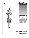
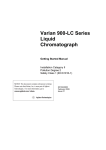
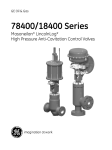
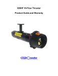
Varian Dual Chamber
Dynamic Mixer
Instruction Manual
Installation Category II
Pollution Degree 2
Safety Class 1 (EN 61010-1)
Publication no. 0391467400
Issue 5
February 2009
Varian Dual Chamber Dynamic Mixer
Varian, Inc. – Serving Industries Worldwide
Biosciences
Pharmaceuticals
Clinical Research and Forensics
Food and Agriculture
Chemical Analysis
Environmental
Fuels and Energy
Material Sciences
Sales and Service Contact Details
North America: 800.926.3000, 925.939.2400
Europe, The Netherlands: 31.118.67.1000
Asia Pacific, Australia: 613.9560.7133
Latin America, Brazil: 55.11.3238.0400
Varian, Inc. Web Site
www.varianinc.com
Varian, Inc. is the owner of copyright on this document and any
associated software. Under law, the written permission of Varian,
Inc. must be obtained before the documentation or the software is
copied, reproduced, translated or converted to electronic or other
machine-readable form, in whole, or in part.
Updated February 2009.
Varian and the Varian logo are trademarks or registered
trademarks of Varian, Inc. in the U.S. and other countries.
© 1998-2009 Varian Inc.
ii
Publication no. 0391467400, Issue 5, February 2009
Varian Dual Chamber Dynamic Mixer
Declaration of Conformity
We hereby declare that the equipment listed below complies with the requirements of:
The Low Voltage Directive 73/23/EEC (93/68/EEC)
The EMC Directive 89/336/EEC (92/31/EEC and 93/68/EEC)
Applicable Standards
LVD
BS EN 61010-1:1993
EMC
BS EN 61326:2003
Equipment Model Number
Varian Dual Chamber Dynamic Mixers
Authorized Representative in the EU
Name: G. A. Wassink
Signed:
Position: Quality Manager
Date: 1 February 2009
Company Name
Address
Varian BV
Herculesweg 8
4338 PL Middelburg
The Netherlands
Telephone
Facsimile
+31 (0) 118 671 000
+31 (0) 118 633 118
Manufacturer
Name: Philip Binns
Signed:
Position: Director of Operations
Date: 1 February 2009
Company Name
Address
Varian Australia Pty Ltd
679 Springvale Road
Mulgrave VIC 3170
Australia
Telephone
Facsimile
+61 (0) 3 9560 7133
+61 (0) 3 9560 7950
Publication number 8 510251600 Febr uary 2009
Publication no. 0391467400, Issue 5, February 2009
iii
Varian Dual Chamber Dynamic Mixer
This page is intentionally left blank.
iv
Publication no. 0391467400, Issue 5, February 2009
Varian Dual Chamber Dynamic Mixer
Contents
General Safety Precautions
1
CE Compliance
1
Electrical Hazards
1
Note, Caution and Warning Messages
2
Service Availability
3
1.
5
Introduction
1.1 General
5
2.
9
Installation
2.1 Unpacking
9
2.2 Plumbing
9
2.2.1
Binary Gradient HPLC Connections
9
2.2.1
Ternary Gradient HPLC Connections
10
2.3 Plumbing Fittings
2.3.1
0.6 mL and 1.2 mL Stainless Steel Mixers
12
12
2.3.2 1.2 mL PEEK, 0.6 mL Titanium and 1.2 mL Titanium
Mixers
12
2.3.3
10 mL PEEK and Titanium mixers
13
2.4 Electrical Connections
13
2.5 Mounting
14
3.
17
Maintenance and Troubleshooting
3.1 Operating Precautions
17
3.2 Mixer Disassembly
17
3.3 Cleaning the Mixer Components
20
3.4 Mixer Reassembly
20
3.4.1
Analytical and Narrowbore Mixers
20
3.4.2
Preparative Mixers
20
Publication no. 0391467400, Issue 5, February 2009
v
Varian Dual Chamber Dynamic Mixer
3.4.3
vi
All Mixers
21
3.5 Checking and Replacing the Outlet Filter Frit
22
3.6 Seal Replacement
23
3.7 Troubleshooting
24
4.
Spare Parts
25
5.
Specifications
27
Publication no. 0391467400, Issue 5, February 2009
Varian Dual Chamber Dynamic Mixer
General Safety Precautions
Follow these safety practices to ensure safe equipment operation:
• Perform periodic leak checks on all supply lines and
pneumatic plumbing.
• Store organic solvents in fireproof, vented and clearly
labeled cabinets so they are easily identified as toxic and/or
flammable materials.
• Do not accumulate waste solvents. Dispose of such
materials through a regulated disposal program and not
through municipal sewage lines.
• This instrument is designed for chromatographic analysis of
appropriately prepared samples. It must be operated using
appropriate gases and/or solvents and within specified
maximum ranges for pressure, flows, and temperatures as
described in this manual. If the equipment is used in a
manner not specified by the manufacturer, the protection
provided by the equipment may be impaired.
• It is the responsibility of the Customer to inform Varian
Customer Support Representatives, if the instrument has
been used for the analysis of hazardous biological,
radioactive, or toxic samples, prior to any instrument service
being performed or when an instrument is being returned to
the Service Center for repair.
CE Compliance
This product complies with the requirements of the European
Union which allow the CE marking to be affixed.
Electrical Hazards
• Replace faulty or frayed power cords immediately with the
same type and rating.
• Make sure that voltage sources and line voltage match the
value for power supply module.
Publication no. 0391467400, Issue 5, February 2009
Page 1 of 28
Varian Dual Chamber Dynamic Mixer
Note, Caution and Warning Messages
This instruction manual is provided to help you establish operating
conditions which will permit safe and efficient use of your
equipment. Special considerations and precautions are also
described in the manual, which appear in the form of Notes,
Cautions and Warnings as described below. It is important that you
operate your equipment in accordance with this instruction manual
and any additional information which may be provided by Varian.
Address any questions regarding the safe and proper use of your
equipment to your local Varian office.
Note
Caution
A note provides information to aid you in obtaining optimal
performance from your instrument.
A Caution message is used when failure to observe instructions
could result in damage to equipment (Varian supplied and/or
other associated equipment).
The meanings of the symbols that may appear alongside warnings
in the documentation or on the instrument itself are as follows:
Chemical hazard
Fire hazard
The following symbol may be used on warning labels attached to
the instrument. When you see this symbol, refer to the relevant
operation or service manual for the correct procedure referred to
by that warning label.
Page 2 of 28
Publication no. 0391467400, Issue 5, February 2009
Varian Dual Chamber Dynamic Mixer
Service Availability
Varian provides a variety of services to support its customers after
warranty expiration. Repair service can be provided by attractively
priced service contracts or on a time and material basis. Technical
support and training can be provided by qualified personnel on
both a contractual or as-needed basis.
Publication no. 0391467400, Issue 5, February 2009
Page 3 of 28
Varian Dual Chamber Dynamic Mixer
This page is intentionally left blank.
Page 4 of 28
Publication no. 0391467400, Issue 5, February 2009
Varian Dual Chamber Dynamic Mixer
1.
1.1
Introduction
General
Varian Dynamic Mixers are dual-chamber high pressure dynamic
mixers designed for binary and ternary gradient HPLC and
preparative HPLC systems.
The unique design of the Varian Dynamic Mixer employs a motor
driven magnet oriented perpendicularly to the mixing chambers. As
the magnet turns, it causes two magnetic stir bars inside the
chambers to rotate by radial drive rather than by axial drive as in
other dynamic mixers. The close proximity of both stir bars to the
rotating drive magnet and the fact that the stir bars rotate in
opposite directions ensures continuous and thorough mixing.
Power is provided by the 9 VAC external transformer. Exploded
views of the mixers can be seen in Figure 8 and Figure 9 in the
Maintenance and Troubleshooting section.
A unique piston-type closure on the outlet of the mixer allows easy
disassembly without tools for cleaning and maintenance. On
analytical and narrowbore mixers the piston incorporates a 2 µm
solvent filter to protect system components from contamination.
The mixer is designed to be plumbed into an HPLC system
between the pumps and the injection valve. A mounting post and a
mast clamp come with the each mixer to allow it to mount to the
side of various HPLC pumps or to mount to the mast of an HPLC
system.
Titanium and PEEK Varian Dynamic Mixers are available for
biochemical applications where 316 stainless steel may be
inappropriate because of corrosion or release of metal ions into
solution. Titanium or PEEK plumbing components can be used
together with PEEK tubing to provide a totally iron-free fluid path.
Publication no. 0391467400, Issue 5, February 2009
Page 5 of 28
Varian Dual Chamber Dynamic Mixer
1
2
3
5
4
6
7
8
9
11
10
12
Figure 1. Section view of the Varian Dynamic analytical mixer body
Where:
1. 10-32 fitting (extra long)
2. Piston
3.
4.
5.
6.
7.
8.
Mixer cap
Seal
Drive magnet
Seal retainer
Frit
Stir bar (upper)
9. Spacer
10. Shaft
11. Stir bar (lower)
12. 10-32 fitting (standard, 2 each)
Page 6 of 28
Publication no. 0391467400, Issue 5, February 2009
Varian Dual Chamber Dynamic Mixer
Solvents from the pumps enter the mixer via the two inlet ports at
the base of the mixer body. They flow into the lower mixing
chamber, where they are mixed by the rotation of the lower stir bar.
The pressure from the pumps forces the mixed mobile phase
upward through the spacer into the upper mixing chamber, where
additional mixing is performed by the opposite rotation of the upper
stir bar. The fully mixed mobile phase is then forced through a
2 µm frit (in analytical and Narrowbore mixers), through the piston,
and out to the rest of the HPLC system.
Since the spacer (the stir-bar cage on preparative mixers) assures
isolation between the two mixing chambers, the Varian Dynamic
mixer acts as a two-stage filter for solvent composition noise. It is
more effective in averaging and reducing solvent composition
noise than a single-chamber mixer of equivalent volume.
The passive seal used in Varian Dynamic mixers is a hollow
molded plastic ring with a circular groove containing an energizing
spring. The side of the seal containing the spring faces into the
mixer chambers. When the mixer is unpressurized, the small
spring inside the seal maintains contact with the mixer bore and
the piston with enough force to seal at low pressures, but not
excessive force to prevent the seal from sliding as the mixer cap is
hand-tightened. When pressurized, mobile phase entering the
mixer body presses the seal against the mixer bore and the piston
with increased force. The increased force maintains sealing action
at HPLC pressures.
Caution
Over tightening the cap with tools may damage the cap or body.
The inlet ports on the analytical and narrowbore mixers accept
standard 10-32 fittings. The outlet port uses an extra-long 10-32
fitting. On the preparative-scale, both inlet and outlet ports accept
1/4-28 fittings for 1/8 in. tubing.
Effective sealing in Varian Dynamic mixers is a function of the
passive sealing mechanism only. The sealing action cannot be
improved by tightening the cap with more force than can be applied
by hand.
Publication no. 0391467400, Issue 5, February 2009
Page 7 of 28
Varian Dual Chamber Dynamic Mixer
This page is intentionally left blank.
Page 8 of 28
Publication no. 0391467400, Issue 5, February 2009
Varian Dual Chamber Dynamic Mixer
2.
2.1
Installation
Unpacking
Before opening the shipping container, check for signs of damage
or rough handling. Report damage to the carrier and your local
Varian sales/service office.
2.2
2.2.1
Plumbing
Binary Gradient HPLC Connections
1
5
7
2
4
8
6
3
Figure 2. Plumbing for a typical binary gradient HPLC
Where:
1. Pressure module
2.
3.
4.
5.
6.
7.
Pump A
Pump B
Mixer
Prime/Purge valve
Column
Injection valve
8. Detector
Publication no. 0391467400, Issue 5, February 2009
Page 9 of 28
Varian Dual Chamber Dynamic Mixer
Warning – Chemical Hazard
Death, serious injury, or damage to skin can result from contact
with chemicals used in HPLC, especially when under high
pressure. Always wear appropriate protective equipment and
clothing.
Caution
To prevent rupture or component damage, the maximum
working pressure of the HPLC system should not exceed the
rated value of any component within the HPLC system.
To connect the mixer to your HPLC system:
1. Connect the high-pressure outlet lines from the pumps to the
mixer inlet ports.
2. Connect the mixer outlet to the prime-purge valve. For
normal use, flow from the pumps is directed through the
injection valve and the column.
3. Connect the outlet from the prime-purge valve to the
injection valve and then to the column.
4. Connect the column outlet to SAMPLE IN on the detector,
and SAMPLE OUT to waste or a fraction collector.
Note
2.2.1
Connect any external pressure module into the HPLC system as
shown in Figure 2.
Ternary Gradient HPLC Connections
Ternary gradient HPLC connections are identical to that of the
binary gradient system except that the high-pressure outlet lines
from pumps B and C are connected through a Tee to the mixer
inlet ports.
Page 10 of 28
Publication no. 0391467400, Issue 5, February 2009
Varian Dual Chamber Dynamic Mixer
1
7
9
2
5
6
8
10
3
4
11
Figure 3. Plumbing for a typical ternary gradient HPLC
Where:
1. Pressure module
2.
3.
4.
5.
6.
7.
Pump A
Pump B
Pump C
Tee
Mixer
Prime/Purge valve
8.
9.
10.
11.
Column
Injection valve
Detector
Fraction collector
Warning – Chemical Hazard
Death, serious injury, or damage to skin can result from contact
with chemicals used in HPLC, especially when under high
pressure. Always wear appropriate protective equipment and
clothing.
Caution
To prevent rupture or component damage, the maximum
working pressure of the HPLC system should not exceed the
rated value of any component within the HPLC system.
Publication no. 0391467400, Issue 5, February 2009
Page 11 of 28
Varian Dual Chamber Dynamic Mixer
Note
2.3
2.3.1
If your system has an external pressure monitor, plumb it between
one pump and either the mixer or the tee, as shown in Figure 3.
Plumbing Fittings
0.6 mL and 1.2 mL Stainless Steel Mixers
For the extra-long fitting on the outlet and the two standard fittings
for the inlet, slide the fitting and ferrule over the 1/16 in. OD tubing
and push the end of the tubing into the port as far as possible.
Holding the tubing in place, finger-tighten the fitting, then tighten ¼
turn more with a wrench. When tightening the outlet fitting, hold the
top of the piston steady with another wrench.
1
2
Figure 4. Compression fittings for the 0.6 mL Narrowbore and
1.2 mL analytical stainless steel mixers
Where:
1. Fitting
2. Ferrule
2.3.2
1.2 mL PEEK, 0.6 mL Titanium and 1.2 mL Titanium
Mixers
Slide the 1/16 in. OD outlet tubing through the one-piece fitting and
ferrule and push the end of the tubing into the port as far as
possible. Holding the tubing in place, finger-tighten the fitting. Do
not use tools to tighten. For both inlet ports, place a fitting and
ferrule on the tubing and tighten in the same manner as the outlet
fitting. Do not use tools to tighten.
Page 12 of 28
Publication no. 0391467400, Issue 5, February 2009
Varian Dual Chamber Dynamic Mixer
1
2
Figure 5. 1.2 mL Titanium Analytical Mixers
Where:
1. Extra-long fitting and ferrule
2. Inlet fitting and ferrule
2.3.3
10 mL PEEK and Titanium mixers
All ports are identical. Slide the fitting and ferrule/ferrule collar over
the 1/8 in. OD tubing as shown and push the end of the tubing into
the port as far as possible. While holding the tubing in place,
finger-tighten the fitting. When tightening the outlet port fitting, hold
the piston steady with another wrench.
Note
When the system plumbing is complete, check for any leaks. If a
leak is found, stop the pumps and tighten the affected fitting just
enough to stop the leak.
1
2 3
Figure 6. Compression fittings for 10 mL PEEK and 10 mL titanium
preparative mixers
Where:
1. Fitting
2. Ferrule collar
3. Ferrule
2.4
Electrical Connections
All Varian Dynamic mixers are designed to run from a 9 VAC
transformer. Plug the transformer into a wall outlet, and insert the
power jack into the receptacle in the rear of the mixer. An LED will
light to indicate the mixer motor is turning and that power is flowing
to the instrument.
Publication no. 0391467400, Issue 5, February 2009
Page 13 of 28
Varian Dual Chamber Dynamic Mixer
Note
Although the mixer motor is extremely robust, disconnecting the
mixer from its power supply when the system is not in use will
increase the life of the motor.
Warning – Fire Hazard
To ensure power ratings are not exceeded, use only the
appropriate Varian supplied wall transformer.
The 9 VAC voltage level does not pose a shock hazard,
however, a slight spark could occur during disconnection of the
power jack or when a live power jack comes into accidental
contact with metal parts on the laboratory bench.
If the mixer is to be disconnected while working around
extremely volatile solvents, the transformer should be unplugged
from the wall before the power jack is disconnected from the
mixer.
2.5
Mounting
Hardware for mounting the mixer to the side of a HPLC pump or to
the mast of an HPLC system is included with the mixer.
To mount the mixer to the side of an HPLC pump:
1. Remove one of the screws on the rear side of the pump.
2. Screw the mounting post into this hole and tighten with a
wrench.
3. Thread the mixer onto the other end of the mounting post
and rotate the instrument clockwise four times to engage
the threads.
4. Lock the mixer in position by tightening the mounting nut
with a wrench.
To mount the mixer to the mast:
Instead of using the mounting post, fasten the mast clamp to the
mixer with the 10-32 x ½ in. screw provided. The mast clamp can
be fitted to the mast and tightened into position with the T screw.
Page 14 of 28
Publication no. 0391467400, Issue 5, February 2009
Varian Dual Chamber Dynamic Mixer
1
4
2
3
Figure 7. Hardware for mounting the mixer.
Where:
1.
2.
3.
4.
Mounting post
Mounting nut
Screw
Mast clamp
Publication no. 0391467400, Issue 5, February 2009
Page 15 of 28
Varian Dual Chamber Dynamic Mixer
This page is intentionally left blank.
Page 16 of 28
Publication no. 0391467400, Issue 5, February 2009
Varian Dual Chamber Dynamic Mixer
3.
Maintenance and
Troubleshooting
The uncomplicated design and rugged construction of the Varian
Dynamic mixers help to keep maintenance to a minimum. When
maintenance is required, the mixer body can be easily
disassembled without tools. Maintenance is limited to the hydraulic
components and fluid pathways through the mixer body.
3.1
Operating Precautions
The following operating precautions will help to keep your mixer in
good condition:
• Always use HPLC-grade solvents. Impurities present in
other grades may contaminate system components.
• Always use a solvent inlet filter to reduce particulate
contamination and to prevent clogging of the mixer frit.
• Never mix, or make a direct change between, immiscible
solvents. Change between them via an intermediate solvent
(or a series) miscible with both.
• After using concentrated salt solutions, flush the mixer
thoroughly with water, then with 50/50 MeOH/water. Leave
the solution in the mixer overnight. Before using the salt
solution again, flush with water thoroughly. If flushing is not
practical, set a low flow rate (0.01 mL/min) to avoid salt
precipitation.
• Avoid knocking or jarring the mixer. Although rugged, it
should always be treated with the degree of care appropriate
for laboratory instrumentation.
3.2
Mixer Disassembly
Figure 8 shows an exploded view of the internal components of an
analytical or narrowbore mixer body. Figure 9 shows the view of
the preparative mixer.
Publication no. 0391467400, Issue 5, February 2009
Page 17 of 28
Varian Dual Chamber Dynamic Mixer
1
1
2
2
3
3
4
4
5
5
6
6
7
7
8
9
8
9
10
10
11
12
11
Figure 8. Exploded view of an analytical or
narrowbore mixer body
Figure 9. Exploded view of a preparative mixer
body
Where:
1. Outlet port
Where:
2.
3.
4.
5.
6.
7.
Mixer cap
Piston
Seal (spring down)
Seal retainer (includes frit)
Stir bar
Spacer
8.
9.
10.
11.
Stir bar
Mixer body
Inlet port
Mixer housing
Page 18 of 28
1. Outlet port
2. Mixer cap
3. Piston
4.
5.
6.
7.
8.
9.
Seal (spring down)
Stir bar cap (top)
Stir bar
Stir bar cage (short end up)
Stir bar
Stir bar cap (bottom)
10. Mixer body
11. Inlet port
12. Mixer housing
Publication no. 0391467400, Issue 5, February 2009
Varian Dual Chamber Dynamic Mixer
To disassemble the mixer:
1. Before you disassemble the mixer, first unplug the
transformer from the wall outlet, and then from the mixer.
2. Unthread the mixer cap by turning it counter-clockwise. The
outlet tubing fitting will still be connected.
3. The piston is held in the mixer body bore by the friction of
the seal. Pull up on the outlet fitting to extract the piston, the
seal, and the seal retainer in analytical and Narrowbore
models.
4. Disconnect the outlet fitting from the piston using two openend wrenches: use a wrench across the flats of the piston
to hold it in place while you loosen the outlet fitting with
another wrench. Finger tight fittings should be removed
without tools. Put the piston assembly and the mixer cap in
a clean, safe place.
5. Disconnect the two inlet fittings at the base of the mixer
body with the wrench or without tools if finger-tight fittings
are used.
6. Analytical and narrowbore mixers: Turn the mixer over to
remove the upper stir bar, the spacer, and the lower stir
bar. These components should fall freely from the mixer
body bore, but you may have to tap the mixer body lightly to
loosen them. Unscrew the seal retainer and pull the seal off
the piston.
7. Preparative Mixers: Turn the mixer over to remove the stir
bar cage. The stir bar cage contains two stir bars and is
capped at both ends. Disassemble the stir bar cage by
pulling off each stir bar cap. Remove both stir bars.
Preparative-scale mixers do not use a seal retainer. Simply
pull the seal off the piston on these models.
Warning – Chemical Hazard
Death, serious injury, or damage to skin can result from contact
with chemicals used in HPLC, especially when under high
pressure. Be careful not to spill solvent from the mixer body bore
during this procedure. Always wear appropriate protective
equipment and clothing.
Publication no. 0391467400, Issue 5, February 2009
Page 19 of 28
Varian Dual Chamber Dynamic Mixer
Caution
Do not use sharp instruments to remove the stir bars, the
spacer, or the stir bar cage. The mixer components or the mixer
body bore may be damaged.
8. The mixer components are now fully disassembled and can
be cleaned or replaced as necessary. Replacing the frit and
seal are described in Sections 3.5 and 3.6.
3.3
Cleaning the Mixer Components
Unless the mixer components are badly contaminated, they are
best cleaned by wiping with a lint-free wipe and using alcohol to
remove any small particulate matter. If the mixer is badly
contaminated, cleaning all fluid path components by sonication is
recommended.
3.4
Mixer Reassembly
Perform the steps in either Section 3.4.1 or Section 3.4.2
depending on your mixer type. Then proceed to Section 3.4.3 to
complete the procedure.
3.4.1
Analytical and Narrowbore Mixers
1. Take one stir bar and hold it above the mixer bore so the
cross vanes are up and down. Drop the stir bar into place.
Drop the spacer into the bore, then the upper stir bar.
2. If you removed the seal, take a replacement seal and place
it on the piston so the spring inside the seal is visible. If the
seal is put in upside down the seal will leak. Push the seal
over the screw threads onto the shoulder. Thread the seal
retainer onto the piston and finger tighten. Do not use tools.
3.4.2
Preparative Mixers
1. Reassemble the stir bar cage: place one stir bar into one
end of the stir bar cage and press-fit the stir bar cap. Both
ends of the stir bar cage are symmetrical and the cage fits
into the mixer bore in either direction.
2. Slide seal so that the spring cavity is facing downward.
Page 20 of 28
Publication no. 0391467400, Issue 5, February 2009
Varian Dual Chamber Dynamic Mixer
3.4.3
All Mixers
1. Press the piston with the seal now attached (with seal
retainer on analytical-scale models) into the mixer body
bore as far as possible.
2. Finger-tighten the mixer cap. Do not over-tighten.
3. Reconnect the outlet line to the mixer. Tighten the outlet
fitting finger tight, then tighten a further 1/3 turn if using non
finger tight fittings. Tighten using two open-end wrenches
as follows: hold the piston steady with a wrench across the
flats while you tighten the outlet fitting with another wrench.
Do not over-tighten. Reconnect the inlet lines to the base of
the mixer body in the same manner.
4. The mixer reassembly is now complete. Connect the power
cord and check that the LED comes on to show mixer
operation.
5. When the plumbing is complete, operate the system to
check for any leaks. If leaks are found, stop the pumps and
tighten the leaky fittings just enough to stop the leak.
Warning – Chemical Hazard
Death, serious injury, or damage to skin can result from contact
with chemicals used in HPLC, especially when under high
pressure. Always wear appropriate protective equipment and
clothing.
Caution
A leak at the top of the mixer may be caused by a damaged
seal. In this case, tightening the outlet fitting further will have no
effect on the leak. Over-tightening the outlet fitting may damage
the fitting or the piston. If the seal is damaged, replace it. (See
Section 3.6.)
Publication no. 0391467400, Issue 5, February 2009
Page 21 of 28
Varian Dual Chamber Dynamic Mixer
3.5
Checking and Replacing the Outlet Filter Frit
(Analytical and Narrowbore Mixers Only)
These mixers incorporate a 2 µm frit pressed into the seal retainer
to protect the downstream components of the HPLC system from
particulate contamination. With normal use, this frit may become
clogged, resulting in restricted flow through the mixer and HPLC
system. To check for restricted flow you will need a pressure
monitor in the HPLC system between the pumps and the mixer.
To check for restricted flow:
1. Open the prime-purge valve so the flow is diverted to
waste.
2. Run the pumps with methanol (rinsing first with water, if
necessary) at a moderate flow rate (1 mL/min) and check
the pressure monitor.
If the frit and the fluid lines are in good condition, the pressure
reading on the monitor should be minimal. A reading over
689.5 kPa (100 psi) indicates that the frit is probably clogged and
needs to be replaced. A clogged frit cannot be cleaned.
The frit can be replaced without fully dismantling the mixer or
disconnecting the outlet tubing:
1. Follow steps 1, 2, and 3 in the procedure in Section 3.2.
2. Loosen and remove the seal retainer (includes frit).
3. Thread the replacement seal retainer and frit onto the
piston. Finger-tighten the seal retainer.
4. Press the piston in the mixer body bore.
5. Replace the mixer cap.
Page 22 of 28
Publication no. 0391467400, Issue 5, February 2009
Varian Dual Chamber Dynamic Mixer
3.6
Seal Replacement
If leaks are seen at the top of the mixer, and the correct outlet
fitting is swaged properly, the seal may need to be replaced.
Caution
Leaks from the top of the mixer cannot be prevented by
tightening the mixer cap. Tightening the mixer cap more than
finger tight may deform the cap or the top of the piston. Never
use tools to tighten the mixer cap.
The seal can be replaced without fully dismantling the mixer or
disconnecting the outlet tubing:
1. Follow steps 1, 2, and 3 in the procedure in Section 3.2.
2. Analytical and narrowbore mixers: Loosen and remove the
seal retainer and frit. Remove the seal by pulling it away
from the piston. Place a replacement seal on the piston so
the spring inside the seal is visible. If the seal is put in
upside down the seal will leak. Push the seal over the
screw threads onto the shoulder. Thread the seal retainer
onto the piston and finger tighten. Do not use tools.
3. Preparative mixers: Remove the seal by pulling it away
from the piston. Slide the seal over the piston so the side of
the seal with the larger outside diameter is closer to the
bottom of the piston.
4. Press the piston, with seal (and seal retainer on analytical
and narrowbore models), all the way into the mixer body
bore.
5. Replace the mixer cap.
Publication no. 0391467400, Issue 5, February 2009
Page 23 of 28
Varian Dual Chamber Dynamic Mixer
3.7
Troubleshooting
Varian Dynamic mixers should give years of trouble-free service
provided they are operated and maintained as outlined in this
manual. However, even with careful use and regular maintenance,
sometimes problems may still arise.
When troubleshooting HPLC systems start with a systematic
approach and then focus on one component of the HPLC system
at a time in a logical progression. Use a process of elimination to
locate any given problem.
Problem: Leaks
Possible Cause
Correction
Loose fittings
Tighten just enough to stop the leak.
Damaged seal
Replace the seal. (See Section 3.6)
Damaged ferrule in
Replace the ferrule. Do not over-tighten.
compression fitting
(See Figure 4)
Incorrect fitting
Reconnect with correct fittings.
Problem: Excessive backpressure
Possible Cause
Correction
Clogged mixer frit
Analytical and narrowbore mixers only.
Replace the frit. (See Section 3.5)
Stir bar/spacer sticking
Dismantle and clean the mixer. Filter
solvents. Check solvent miscibility. (See
Section 3.2)
Blocked tubing
Loosen the fitting after each component
to find the blockage. Replace the
affected tubing.
Damaged ferrule in the
Replace the ferrule. Do not over-tighten.
compression fitting
(See Figure 4)
Problem: Unsatisfactory peaks or baseline
Possible Cause
Correction
No power to mixer
Check that the power cord is fully
inserted into an outlet and into the
power jack of the mixer. Check that the
LED indicator is on.
Page 24 of 28
Publication no. 0391467400, Issue 5, February 2009
Varian Dual Chamber Dynamic Mixer
4.
Spare Parts
0393503301
Transformer adapter, AC/AC,120 VAC to 9 VAC
0393503101
Transformer adapter, AC/AC, 240 VAC to 9 VAC
0393503201
Transformer adapter, AC/AC, 230 to 9 VAC
R007000507
Mixing seal retainer with Titanium frit 10 µm
R007000054
Inlet solvent filter, 2 µm, 10 mm part number R000083915
R007100151
Seal retainer assembly, 1.2 mL mixer
R002540006
Seal, stainless steel 10 mm
R002540009
Mixing seal, Titanium, 10 mm
R002540014
Pressure seal, 0.715 in. ID, UHMW/perf
1500141000
Nut, GC, 1/16 in., SST
2869453300
Ferrule, 1/16 in., CPI, SST
R007010062
Bushing, extra long
R000FTF130
Male nut 10-32 PEEK
R000FTF300
High pressure nut, ferrule PEEK 10-32
R0000LT200
High pressure ferrule, PEEK ¼-28 x 1/8 in. OD tubing
R0000LT210
Nut, PEEK ¼-28 x 1/8 in. OD tubing
R002500002
Magnetic mixing stir bar, 3/8 in. x 5/16 in.
0393502801
Mixer mounting kit
Publication no. 0391467400, Issue 5, February 2009
Page 25 of 28
Varian Dual Chamber Dynamic Mixer
This page is intentionally left blank.
Page 26 of 28
Publication no. 0391467400, Issue 5, February 2009
Varian Dual Chamber Dynamic Mixer
5.
Specifications
Part Number
Scale
0393502100
Narrowbore
0393509700
Narrowbore
0393501801
Analytical
0393502001
Analytical
0393501901
Analytical
0393502301
Preparative
0393502201
Preparative
Required
Fittings
10-32
10-32
10-32
10-32
10-32
¼ - 28
¼ - 28
Product
Materials in Fluid Contact
Narrowbore Mixer
0.6 mL, SS
Narrowbore Mixer
0.6mL, TI
Dual Chamber Mixer
1.2 mL, SS
Dual Chamber Mixer
1.2 mL, PK
Dual Chamber Mixer
1.2 mL, TI
Dual Chamber Mixer
10 mL, PK
Dual Chamber Mixer
10 mL, TI
316 Stainless Steel, Teflon, Hastelloy,
Fluoroloy-12
TItanium, Teflon, Fluorowhite
Tube OD
1/16 in.
1/16 in.
1/16 in.
1/16 in.
1/16 in.
1/8 in.
1/8 in.
316 Stainless Steel, Teflon, Hastelloy,
Fluoroloy-12
Titanium, Teflon, PEEK, UHMWPE,
Fluorowhite
Titanium, Teflon, Fluorowhite
PEEK, Teflon, Perfluoro, Fluorowhite
Titanium, Teflon, Perfluoro, Fluorowhite
Mixing Chamber
Pressure Rating, Max.
41.4 MPa (6000 psi)
27.6 MPa (4000 psi)
41.4 MPa (6000 psi)
27.6 MPa (4000 psi)
41.4 MPa (6000 psi)
13.8 MPa (2000 psi)
41.4 MPa (6000 psi)
Publication no. 0391467400, Issue 5, February 2009
Mixing Chamber Volume
in Each Chamber
0.3 mL
0.3 mL
0.6 mL
0.6 mL
0.6 mL
5 mL
5 mL
Total
Volume
0.6 mL
0.6 mL
1.2 mL
1.2 mL
1.2 mL
10 mL
10 mL
Page 27 of 28
Varian Dual Chamber Dynamic Mixer
Item
Motor speed
Operating voltages
Power
Operating frequency
Power ratings
(transformer dependent)
Indoor use
Operating temperature range
Relative humidity
Altitude
Installation category
Pollution degree
Weight
Size
Mixer module
AC adapter
Page 28 of 28
Specification
300 rpm at 60 Hz line frequency
250 rpm at 50 Hz line frequency
Line voltage: 120/230/240 VAC
Unit voltage: 9 VAC
8 VA
50/60 Hz
USA Wall transformer, 9 VAC, 500 mA
Europe Wall transformer, 9 VAC, 500 mA
UK Wall transformer, 9 VAC, 500 mA
4-60 °C
10 to 90%
Up to 2000 m
11
2
Approximately 0.8 kg (1.8 lb)
4.2 x 7.5 x 8.8 cm (1.7 x 3.0 x 3.6 in.)
6.0 x 5.05 x 4.1 cm (2.3 x 2.0 x 1.6 in.)
Publication no. 0391467400, Issue 5, February 2009