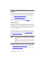
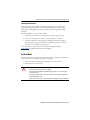
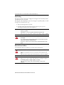
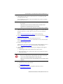
1
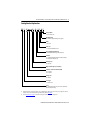
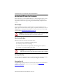
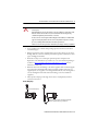
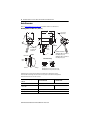
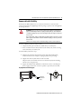
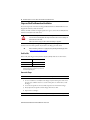
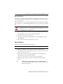
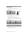
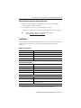
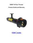
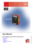
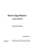
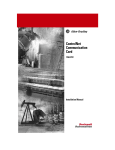
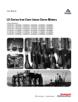
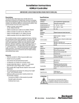
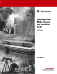
Installation Instructions
Kinetix VP Stainless-steel Servo Motor with
130 mm and 165 mm Frame Size
Catalog Numbers VPS-B1304D-PJ12DF, VPS-B1653D-PJ12DF
Topic
Page
Catalog Number Explanation Important User Information
3
Catalog Number Explanation
3
About the Kinetix VP Stainless Steel Servo Motors
4
Before You Begin
4
Install the Motor
7
Motor Dimensions
10
Connector Data
11
Motor Load Force Ratings
12
Remove and Install a Shaft Key
13
Slinger and Shaft Seal Removal and Installation
14
Specifications
17
Motor Cables and Accessory Kits
18
18
2 Kinetix VP Stainless-steel Servo Motor with 130 mm and 165 mm Frame Size
Important User Information
Read this document and the documents listed in the additional resources section about installation, configuration, and operation of
this equipment before you install, configure, operate, or maintain this product. Users are required to familiarize themselves with
installation and wiring instructions in addition to requirements of all applicable codes, laws, and standards.
Activities including installation, adjustments, putting into service, use, assembly, disassembly, and maintenance are required to be
carried out by suitably trained personnel in accordance with applicable code of practice.
If this equipment is used in a manner not specified by the manufacturer, the protection provided by the equipment may be impaired.
In no event will Rockwell Automation, Inc. be responsible or liable for indirect or consequential damages resulting from the use or
application of this equipment.
The examples and diagrams in this manual are included solely for illustrative purposes. Because of the many variables and
requirements associated with any particular installation, Rockwell Automation, Inc. cannot assume responsibility or liability for actual
use based on the examples and diagrams.
No patent liability is assumed by Rockwell Automation, Inc. with respect to use of information, circuits, equipment, or software
described in this manual.
Reproduction of the contents of this manual, in whole or in part, without written permission of Rockwell Automation, Inc., is
prohibited.
Throughout this manual, when necessary, we use notes to make you aware of safety considerations.
WARNING: Identifies information about practices or circumstances that can cause an explosion in a hazardous
environment, which may lead to personal injury or death, property damage, or economic loss.
ATTENTION: Identifies information about practices or circumstances that can lead to personal injury or death,
property damage, or economic loss. Attentions help you identify a hazard, avoid a hazard, and recognize the
consequence.
IMPORTANT Identifies information that is critical for successful application and understanding of the product.
Labels may also be on or inside the equipment to provide specific precautions.
SHOCK HAZARD: Labels may be on or inside the equipment, for example, a drive or motor, to alert people that
dangerous voltage may be present.
BURN HAZARD: Labels may be on or inside the equipment, for example, a drive or motor, to alert people that
surfaces may reach dangerous temperatures.
ARC FLASH HAZARD: Labels may be on or inside the equipment, for example, a motor control center, to alert
people to potential Arc Flash. Arc Flash will cause severe injury or death. Wear proper Personal Protective
Equipment (PPE). Follow ALL Regulatory requirements for safe work practices and for Personal Protective
Equipment (PPE).
Rockwell Automation Publication VPS-IN002B-EN-P - December 2014
Kinetix VP Stainless-steel Servo Motor with 130 mm and 165 mm Frame Size 3
Catalog Number Explanation
VP S - B xxx x D - P J 1 2 D F
Factory Options
F = 5 m (16.4 ft) cable
Mounting Flange
D = IEC metric, tapped mounting holes (type FT)
Brake
2 = No brake
Connector
1 = Single SpeedTec DIN connector
Enclosure/Shaft Key/Shaft Seal
J = IP66/IP67/IP69K housing/shaft key/shaft seal
Feedback
P = 18-bit absolute multi-turn (4096 revolutions) digital
encoder (Hiperface DSL protocol)
Rated Speed (1)
D = 3000 rpm
Magnet Stack Length (3 or 4 stacks) (2)
Frame Size – Bolt Circle Diameter (BCD)
130 = 130 mm
165 = 165 mm
Voltage Class
B = 400V AC
Series Type
S = Stainless steel
Series
VP = Permanent magnet rotary servo motors optimized to
Kinetix® 5500 drive ratings
(1)
Rated speed hierarchy is for comparative purposes only. Use Motion Analyzer software to size and select motors for your application, and/or the
torque/speed curves in the Kinetix 5500 Drive System Design Guide, publication GMC-RM009.
(2)
Refer to Motor Dimensions on page 11 for dimensional changes that result from the number of magnet stacks.
Rockwell Automation Publication VPS-IN002B-EN-P - December 2014
4 Kinetix VP Stainless-steel Servo Motor with 130 mm and 165 mm Frame Size
About the Kinetix VP Stainless Steel Servo Motors
Kinetix® VP stainless steel motors (Bulletin VPS) feature a multi-turn high-resolution encoder.
These compact, brushless servo motors meet the unique needs of hygienic manufacturing
environments, such as food, beverage, brewing, dairy, health and beauty, and pharmaceutical
products.
Before You Begin
You are responsible for inspecting the equipment before you accept the shipment from the
freight company. Check the items you receive against your purchase order. Notify the carrier of
shipping damage or missing items immediately. Store or operate your motor in a clean and dry
location within the Environmental Specifications on page 17.
ATTENTION: To avoid personal injury and damage to the motor, do not lift or handle the motor by the
motor shaft. The cap on the shaft can come loose and cause you to drop the motor.
Before You Install the Motor
Perform these inspection steps before you install the motor.
1. Remove the motor carefully from its shipping container.
2. Visually inspect the motor for any damage.
3. Examine the motor frame, front output shaft, and mounting pilot for any defects.
4. Notify the carrier of shipping damage immediately.
ATTENTION: Do not open and modify the motor.
Failure to observe these safety procedures could result in personal injury or damage to equipment.
Removing the Shaft Cap
Remove the protective cap installed on the motor shaft with your hand or by prying it off with a
screwdriver. Do not use a hammer or other tools as they can damage the motor shaft.
Prolonging Motor Life
Thoughtful design and proper maintenance can increase the life of a servo motor. Follow these
guidelines to maximize the life of a servo motor operated within the Environmental
Specifications on page 17.
Rockwell Automation Publication VPS-IN002B-EN-P - December 2014
Kinetix VP Stainless-steel Servo Motor with 130 mm and 165 mm Frame Size 5
ATTENTION: Do not spray liquids under high pressure directly on the connector, the motor, or the
enclosure joints.
Fluids under high pressure can be forced into the connector, resulting in an electrical short circuit.
Fluids also can be forced around worn seals, and contaminate the motor bearings. Bearing
contamination significantly shortens the life of a servo motor.
The motor connector is not designed to withstand high-pressure washdown, or washdown with
aggressive cleaning compounds. Position the connector away from direct exposure to cleaning
processes, for example, within washdown-rated conduit or junction boxes.
Failure to observe these safety procedures could result in personal injury or damage to equipment.
• Do not install the motor with the shaft pointing upward, as this increases the risk of
contaminant ingress.
• If design requirements permit, provide shields or junction boxes that protect the motor
housing, shaft seals, connector, and their junctions from product contamination, caustic
agents, and high pressure fluids.
• Shaft seals are subject to wear and require periodic inspection and replacement.
Replacement is recommended every 3 months, not to exceed 12 months, depending on
use. Refer to Slinger and Shaft Seal Removal and Installation on page 14 for more
information on shaft seals.
• If desired, seal the motor front flange to the driven equipment with a bead of food-grade
room temperature vulcanizing (RTV) silicone around the periphery of the motor to
equipment joint. Use of a gasket, or non food-grade RTV silicone, on the mating surfaces
can cause misalignment of the shaft and result in damage to the motor and driven
equipment.
• Always provide a drip loop in the single motor cable to carry liquids away from the
connection to the motor.
Create a Drip Loop
The cable lacks a drip loop.
Position the motor so that the cable enters from beneath
the motor, and forms a drip loop, as shown here.
Rockwell Automation Publication VPS-IN002B-EN-P - December 2014
6 Kinetix VP Stainless-steel Servo Motor with 130 mm and 165 mm Frame Size
Using Shaft Seals
A seal is installed on the motor shaft to protect the front bearing from fluids or fine dust that can
contaminate the motor bearing and reduce its lifetime. The IP66, IP67, or IP69K rating for the
motor depends on the shaft seals and the environmental seal on the connector and cable:
• Refer to Positive Air-pressure Accessory Kit on page 18 to find the catalog numbers of
seal kits available for your motor.
• Refer to Environmental Specifications on page 17 for brief descriptions of IP ratings.
Refer to Kinetix Motion Control Selection Guide, publication GMC-SG001, to find
environmentally sealed cables that are compatible with the Bulletin VPS motors.
Using Couplings and Pulleys
Mechanical connections to the motor shaft, such as couplings and pulleys, require a torsionally
rigid coupling or a reinforced timing belt. The high dynamic performance of servo motors can
cause couplings, pulleys, or belts to loosen or slip over time. A loose or slipping connection causes
system instability and can damage the motor shaft. All connections between the machine and the
motor shaft must be rigid to achieve acceptable system response. Periodically inspect
connections to verify their rigidity.
When mounting couplings or pulleys to the motor shaft, verify that the connections are properly
aligned and that axial and radial loads are within the specifications of the motor. If you attach a
sealed gearbox to the motor shaft, remove the slinger (see Remove the Slinger on page 14).
Refer to Motor Load Force Ratings on page 12 for guidelines on how to achieve 20,000 hours of
motor bearing life.
ATTENTION: Damage can occur to the motor bearings and the feedback device if sharp impact is
applied to the shaft during installation of couplings and pulleys. Damage to the feedback device
can result from applying leverage to the motor mounting face when removing devices mounted on
the motor shaft.
Do not strike the shaft, couplings, or pulleys with tools during installation or removal. Use a wheel
puller to apply pressure from the user end of the shaft when attempting to remove any device from
the motor shaft.
Failure to observe safety precautions could result in damage to the motor and its components.
A shaft key provides a rigid mechanical connection with the potential for self-alignment, but the
key must be properly installed in the keyway. Refer to these sections for additional information:
• Shaft, Pilot, and Keyway Dimensions, mm (in.) on page 10 for information about the
key and shaft keyway dimensions
• Remove and Install a Shaft Key on page 13 for recommendations on how to remove and
install a shaft key
Rockwell Automation Publication VPS-IN002B-EN-P - December 2014
Kinetix VP Stainless-steel Servo Motor with 130 mm and 165 mm Frame Size 7
Preventing Electrical Noise
Electromagnetic interference (EMI), commonly called electrical noise, can reduce motor
performance. Effective techniques to counter EMI include filtering the AC power, using
shielded cables, shielding signal cables from power wiring, and practicing good grounding
techniques.
Follow these guidelines to avoid the effects of EMI:
• Isolate the power transformers or install line filters on all AC input power lines.
• Do not route the single motor cable over the vent openings on servo drives.
• Ground all equipment by using a single-point parallel ground system that employs
ground bus bars or large straps. If necessary, use additional electrical noise reduction
techniques to reduce EMI in noisy environments.
See System Design for Control of Electrical Noise Reference Manual, publication
GMC-RM001, for additional information on reducing EMI.
Install the Motor
Motor installation must comply with all local regulations and use of equipment and installation
practices that promote safety and electromagnetic compatibility:
• All motors include a mounting pilot for aligning the motor on a machine.
• Preferred fasteners are stainless steel.
ATTENTION: Unmounted motors, disconnected mechanical couplings, loose shaft keys, and
disconnected cables are dangerous if power is applied.
Verify that disassembled equipment is identified (tagged-out) and access to electrical power is
restricted (locked-out).
Before applying power to the motor, remove the shaft key and other mechanical couplings that
could be thrown from the shaft.
Failure to observe these safety procedures could result in personal injury or damage to equipment.
Rockwell Automation Publication VPS-IN002B-EN-P - December 2014
8 Kinetix VP Stainless-steel Servo Motor with 130 mm and 165 mm Frame Size
Cable Shielding
The single motor cable contains power and digital encoder signals. It must be shielded, and the
cable shield must connect to ground.
Knowledgeable cable routing improves system electromagnetic compatibility (EMC). To install
the single motor cable, follow these steps.
1. Keep the cable length as short as possible.
2. Ground both ends of the cable shield and twist the signal wire pairs to prevent
electromagnetic interference from other equipment.
SHOCK HAZARD: High voltage can be present on the shields of the single motor cable if the
shields are not grounded.
Verify that there is a connection to ground for all shields in the single motor cable.
Failure to observe these safety procedures could result in personal injury or damage to equipment.
ATTENTION: The overall shield on the motor cable must be grounded to obtain an effective
encoder signal.
The encoder data signal is transmitted through an impedance-matched twisted-wire pair that
requires effective shielding for optimum performance.
Be sure there is an effective connection between the motor cable shield and the drive system
ground.
Mount and Connect the Motor
To install a Bulletin VPS motor, follow these procedures and recommendations.
ATTENTION: Servo motors are not for direct connection to an AC power line.
Servo motors are designed for connection to a servo drive that controls the application of AC
power.
Failure to observe these safety precautions could result in damage to the motor and equipment.
ATTENTION: Do not strike the shaft, couplings, or pulleys with tools during installation or removal.
Damage can occur to the motor bearings and the feedback device if you apply a sharp impact to
the shaft during installation of couplings and pulleys, or a shaft key.
Failure to observe these safety procedures could result in damage to the motor and its
components.
Rockwell Automation Publication VPS-IN002B-EN-P - December 2014
Kinetix VP Stainless-steel Servo Motor with 130 mm and 165 mm Frame Size 9
1. Allow sufficient clearances in the area of the motor for it to stay within its specified
operating temperature range.
Do not install the motor in an area with restricted airflow. Keep other heat producing
devices away from the motor.
BURN HAZARD: Outer surfaces of the motor can reach high temperatures, 125 °C (275 °F), during
motor operation.
Take precautions to prevent accidental contact with hot surfaces. Consider motor surface
temperature when selecting motor mating connections and cables.
Failure to observe these safety procedures could result in personal injury or damage to equipment.
Obtain the specified motor thermal rating by mounting the motor on a surface with heat
dissipation equivalent to a 304.8 x 304.8 x 12.7 mm (12 x 12 x 0.5 in.) aluminum
heatsink.
Refer to Environmental Specifications on page 17 for the operating range.
2. Determine the radial and axial shaft load limitations of your motor by referring to Motor
Load Force Ratings on page 12.
3. Position the motor with the cable connections beneath the motor.
Refer to Create a Drip Loop on page 5 for a visual reference of correct motor and cable
positioning.
4. Properly mount and align the motor.
The index pulse occurs on the encoder when the shaft key is aligned with the connector.
Refer to Motor Dimensions on page 10 for a visual reference of this alignment.
5. Attach the single motor cable that transmits the power and digital encoder signals as
described below.
a. Carefully align the cable connector with the motor cable connector.
b. Align the flat surface on the top of the motor cable connector with the flat surfaces
on the cable connector.
ATTENTION: Verify proper alignment and then hand-tighten the keyed connector.
Do not use tools, or apply excessive force, when mating the cable to the motor connector. If the
connectors do not go together with light hand force, realign and try again.
Failure to observe these safety procedures could result in damage to the motor and cable, and their
components.
c. Hand-tighten the knurled collar one-quarter turn to fully seat the cable connector.
d. Verify that the cable is properly shielded.
See Cable Shielding on page 8.
e. Form a drip loop in the cable to carry liquids away from the connector.
See Create a Drip Loop on page 5.
Rockwell Automation Publication VPS-IN002B-EN-P - December 2014
10 Kinetix VP Stainless-steel Servo Motor with 130 mm and 165 mm Frame Size
Motor Dimensions
Refer to Motor Dimensions on page 11 for Bulletin VPS motor dimensions.
Mounting Dimension References, mm (in.)
L
P
LB
S (dia. hole) on
M (bolt circle)
L-LB
T
HD
D
AC
N
CAR
Removable Plug
for Optional Air
Pressure Kit
Flush to Pilot
See Detail A
(cable
bend
radius)
CAB
Shaft End Threaded Hole:
VPS-B1304D - M8 x 1.25-6H Thread
Thread Depth 19.0 (0.75)
VPS-B1653D - M10 x 1.5-6H Thread
Thread Depth 22.0 (0.87)
LE
Detail A
Shaft Detail with Key
Flush to
Shaft
GE
F
Shaft Seal
Slinger
Key Supplied:
VPS-B1304D = 8 x 7 x 32 (0.315 x 0.276 x 1.26)
VPS-B1653D = 8 x 7 x 40 (0.315 x 0.276 x 1.575)
Bulletin VPS motors are designed to metric dimensions. Inch dimensions are mathematical conversions.
Dimension CAB is the total length of the cable and the connector, but does not include the mounting hardware.
Dimension LE measures to the center of the connector.
Shaft, Pilot, and Keyway Dimensions,
mm (in.)
VPS-B1304D-PJ12DF
Flush to pilot
±0.83 (0.032)
Flush to shaft
Ø 24.94 ±0.05 (0.982 ± 0.002)
Keyway width (F)
7.96…8.00 (0.314…0.315)
Keyway depth (GE)
4.00…4.20 (0.158…0.165)
Rockwell Automation Publication VPS-IN002B-EN-P - December 2014
VPS-B1653D-PJ12DF
Ø 29.92 ±0.05 (1.178 ± 0.002)
Kinetix VP Stainless-steel Servo Motor with 130 mm and 165 mm Frame Size 11
Motor Dimensions
D (1)
AC
HD
L
L-LB (2)
LB
LE (3)
Ø mm (in.)
Ø mm (in.)
mm (in.)
mm (in.)
mm (in.)
mm (in.)
mm (in.)
VPS-B1304D-PJ12DF
24.0
(0.94)
127.1
(5.00)
164.0
(6.4)
266.0
(10.47)
50.0
(1.97)
216.0
(8.5)
185.0
(7.3)
VPS-B1653D-PJ12DF
28.0
(1.10)
168.3
(6.63)
198.0
(7.8)
396.4
(15.60)
60.0
(2.36)
336.4
(13.24)
302.0
(11.9)
Motor Cat. No.
(1)
Tolerance for this dimension is: VPS-B1304D, Ø 23.996…24.009 (0.9448…0.9451); VPS-B1653D, Ø 27.996…28.009 (1.1022…1.1027).
(2)
Tolerance for this dimension is ±0.7 mm (±0.03 in.).
(3)
Measures to center of the connector.
Motor Dimensions (continued)
M
N (1)
P (2)
S (3)
T
CAB (4)
CAR (5)
Ø mm (in.)
Ø mm (in.)
Ø mm (in.)
mm (in.)
mm (in.)
m (ft)
Bend radius
VPS-B1304D-PJ12DF
130.0
(5.118)
110.0
(4.33)
143.2
(5.64)
9.0
(0.35)
3.38
(0.133)
5.0 (16.4)
90°
VPS-B1653D-PJ12DF
165.0
(6.496)
130.0
(5.11)
181.0
(7.13)
11.0
(0.43)
3.38
(0.133)
5.0 (16.4)
90°
Motor Cat. No.
(1)
Tolerance for this dimension is: VPS-B1304D, Ø 109.991…110.013 (4.3303…4.3312); VPS-B1653D, Ø 129.991…130.014 (5.1178…5.1187).
(2)
This dimension is the largest diameter on the motor housing.
(3)
VPS-B1304D, M8 x 1.25-6H thread, thread depth 9.0 (0.35); VPS-B1653D, M10 x 1.5-6H thread, thread depth 11.0 (0.43).
(4)
This dimension includes the total length of the cable and the connector, but does not include mounting hardware.
(5)
Single motor cables do not have a continuous flex rating; the specified cable bend radius is a one-time bend.
Connector Data
This section identifies the power and data encoder pins on the motor connector.
M23 Motor Connector Pinouts
Pin
A
B
C
E
F
G
H
L
Signal Name
Phase U
Phase V
Phase W
Ground
Data+
Reserved
Reserved
DataReserved
B
A
C
G
F
L H E
Rockwell Automation Publication VPS-IN002B-EN-P - December 2014
12 Kinetix VP Stainless-steel Servo Motor with 130 mm and 165 mm Frame Size
Motor Load Force Ratings
Motors can operate with a sustained shaft load. The figure shows radial and axial load force
locations, and the tables provide maximum values for each force.
Load Forces on Motor Shaft
Radial Load Force is applied at center of shaft extension.
Axial Load Force
The tables represent 20,000-hour L10 bearing fatigue life at various loads and speeds. The
20,000-hour life does not account for possible application-specific life reduction that can occur
due to bearing grease contamination from external sources.
Loads are measured in kilograms; pounds are mathematical conversions.
Radial Load Force Ratings
500 rpm
1000 rpm
2000 rpm
3000 rpm
Motor Cat. No.
kg
(lb)
kg
(lb)
kg
(lb)
kg
(lb)
VPS-B1304D-PJ12DF
140
(308)
111
(244)
89
(196)
77
(169)
VPS-B1653D-PJ12DF
–
–
154
(338)
122
(268)
106
(234)
Axial Load Force Ratings with Maximum Radial Load
500 rpm
1000 rpm
2000 rpm
3000 rpm
Motor Cat. No.
kg
(lb)
kg
(lb)
kg
(lb)
kg
(lb)
VPS-B1304D-PJ12DF
49
(108)
36
(79)
27
(59)
22
(48)
VPS-B1653D-PJ12DF
–
–
52
(115)
39
(85)
32
(71)
Axial Load Force Ratings with Zero Radial Load
500 rpm
1000 rpm
2000 rpm
3000 rpm
Motor Cat. No.
kg
(lb)
kg
(lb)
kg
(lb)
kg
(lb)
VPS-B1304D-PJ12DF
69
(152)
51
(112)
38
(83)
31
(68)
VPS-B1653D-PJ12DF
–
–
68
(149)
50
(109)
42
(92)
Rockwell Automation Publication VPS-IN002B-EN-P - December 2014
Kinetix VP Stainless-steel Servo Motor with 130 mm and 165 mm Frame Size 13
Remove and Install a Shaft Key
Shaft keys for the BulletinVPS motors are constructed of stainless steel - 300 series with a
tolerance for interference fit (slightly larger than the opening) to provide a secure and rigid fit for
the mating connection.
ATTENTION: Damage can occur to the motor bearings and the feedback device if sharp impact is
applied to the shaft during installation of couplings and pulleys. Damage to the feedback device
can result from applying leverage to the motor mounting face when removing devices mounted on
the motor shaft.
Do not strike the shaft, couplings, or pulleys with tools during installation or removal. Use a wheel
puller to apply pressure from the user end of the shaft when attempting to remove any device from
the motor shaft.
Failure to observe safety precautions could result in damage to the motor and its components.
To remove a shaft key, perform one of these actions:
• Grasp the key with a plier or similar tool, and lift the key out of the key slot.
• Insert a screwdriver between the key and the bottom of the key slot, and use a levering
action to lift the key out of the key slot.
To install a shaft key, follow these steps.
1. Verify that the replacement key matches the keyway in the shaft and the mating
mechanical connection, for example, a coupling or pulley, before proceeding.
2. Align the front of the key with the front of the motor shaft.
This prevents the curved end-of-cut at the motor end of the keyway from interfering
with the correct seating of the key.
3. Support the underside of the shaft diameter with a fixture, and use a controlled press
device to apply a constant force across the top surface to press the key into the shaft.
Key Alignment and Shaft Support
Key
Shaft
Key Alignment
Radiused Cut for
Keyway
Support for Shaft
and Motor
Rockwell Automation Publication VPS-IN002B-EN-P - December 2014
14 Kinetix VP Stainless-steel Servo Motor with 130 mm and 165 mm Frame Size
Slinger and Shaft Seal Removal and Installation
The shaft seal provides environmental sealing for BulletinVPS motors. BulletinVPS motors are
shipped with a Fluoroloy shaft seal installed.
Lubricate the shaft seals with a food-grade polyurea base grease, such as Chevron FM (NLGI 2).
Lubricant is included in each shaft seal kit.
ATTENTION: Damage to the motor surface where the slinger and shaft seal make contact can
cause excessive wear and early failure of the slinger and shaft seal. Do not scratch or damage the
surface of the motor or the shaft.
Failure to observe these safety procedures could result in damage to equipment.
Remove the shaft seal by performing the following procedures. If a sealed gearbox is to be
attached to the motor shaft, perform only the Remove the Slinger procedure below.
TIP
Remove the shaft key, if the motor is so equipped, before performing the following steps. Refer
to Remove and Install a Shaft Key on page 13.
Shaft Seal Kits
Shaft seal kit (with slinger) for Polytetrafluoroethylene (PTFE) shaft seals are shown below.
Motor Cat. No.
Shaft Seal Cat. No. (1)
VPS-B1304D-PJ12DF
MPS-SST-A45B45
VPS-B1653D-PJ12DF
MPS-SST-F165
(1)
Shaft seals are subject to wear and require periodic inspection and
replacement. Replacement is recommended every 3 months, not to
exceed 12 months, depending on use.
Remove the Slinger
IMPORTANT
Do not scratch or damage the motor shaft or mounting surface.
1. Use two screwdrivers to carefully lever the slinger away from the faceplate of the motor.
You must create sufficient clearance to attach a wheel-puller, or a similar device, under
the slinger.
2. Center the wheel-puller on the motor shaft and position its arms under the slinger.
3. Slowly adjust the wheel-puller to lift the slinger off the motor shaft.
4. Dispose of the used slinger.
IMPORTANT
Do not contaminate other surfaces or objects with foreign material from the slinger.
Rockwell Automation Publication VPS-IN002B-EN-P - December 2014
Kinetix VP Stainless-steel Servo Motor with 130 mm and 165 mm Frame Size 15
Remove the Shaft Seal
The shaft seal can be safely removed by partially inserting an appropriately sized screw or bolt
into the face of the shaft seal. The head of the screw or bolt provides a convenient point to grasp
and remove the shaft seal.
Before installing the screw, create a pilot hole appropriate for the screw being used. Use masking
tape or a depth sleeve to establish a drilling depth limit of 4 mm (0.16 in.) from the tip of the drill
bit.
ATTENTION: Do not drill into the shaft seal deeper than 4 mm (0.16 in.).
Drilling and inserting a screw completely through the shaft seal can damage the motor bearings,
and require factory service to repair the motor.
1. Drill a pilot hole in the face of the shaft seal less than the depth limit specified above.
Be sure the drill does not come in contact with the shaft seal bore.
2. Thread the screw or bolt into the pilot hole.
3. Lift the shaft seal from the motor by grasping the screw head and slightly rotating the
seal while pulling.
4. Inspect and clean the shaft and sealing surfaces as necessary.
Replace the Shaft Seal
No tools are required to install the replacement shaft seal.
IMPORTANT
This shaft seal requires a lubricant to reduce wear. The lubricant is supplied in the kit.
1. Apply the provided grease to the inner ring of the shaft seal and motor shaft.
2. Center the shaft seal on the mounting surface of the motor with the seal oriented in the
same manner as the removed seal.
3. Press the shaft seal into the seal recess by applying pressure with your fingertips in a
circular fashion to slowly seat the shaft seal in place.
The surface of the seal must be 0.6 mm (0.02 in.) below the pilot surface.
4. Verify that the outer and inner circumference of the shaft seal is fully seated into
position.
TIP
To verify that the shaft seal is fully seated into position, run your fingertip around the
seal-to-motor joint and feel for irregularities in the shaft seal, or an uneven alignment where
the shaft seal contacts the motor.
Rockwell Automation Publication VPS-IN002B-EN-P - December 2014
16 Kinetix VP Stainless-steel Servo Motor with 130 mm and 165 mm Frame Size
Install the Replacement Slinger
1. Install a threaded rod and nut in the shaft alignment hole.
The table below lists the diameter and threading of alignment holes, and a recommended
rod length for each motor.
Hex Nut and Threaded Rod Sizing
Motor
Threaded Rod Size with Recommended
Length in mm (in.)
VPS-B1304D-PJ12DF
M8 x 1.25 thread size x 203 (8.0)
VPS-B1653D-PJ12DF
M10 x 1.5 thread size x 216 (8.5)
Threaded Shaft
Adjustment Nut
Washer
Socket
Lock Nut
Slinger
Motor
2. Tighten the nut on the threaded rod against the end of the motor shaft.
This prevents the threaded rod from backing out of the motor shaft during this
removal/installation procedure.
3. Position the slinger squarely on the end of the motor shaft.
4. Place a deep well socket, a larger washer, and a nut on the threaded rod.
Use a socket larger than the shaft diameter to provide sufficient clearance between the
inside surface of the socket and the motor shaft. The table below lists shaft diameters for
various motor sizes.
Motor Shaft and Slinger Diameters
Motor Shaft Diameter
Slinger Outside Diameter
mm (in.)
mm (in.)
VPS-B1304D-PJ12DF
24.0 (0.94)
70.0 (2.75)
VPS-B1653D-PJ12DF
28.0 (1.10)
82.6 (3.25)
Motor
5. Tighten the nut to force the washer, socket, and slinger down the shaft.
IMPORTANT
Grasp the slinger tightly by hand to prevent shaft and slinger rotation in the next steps.
If additional travel is required to seat the slinger, add a section of hollow pipe or a similar
item behind the socket.
6. Stop moving the slinger down the shaft approximately 3 mm (0.125 in.) before the
slinger contacts the mounting surface of the motor.
Rockwell Automation Publication VPS-IN002B-EN-P - December 2014
Kinetix VP Stainless-steel Servo Motor with 130 mm and 165 mm Frame Size 17
Adjust the Clearance between the Slinger and Motor Face
1. Position two 0.5 mm (0.02 in.) feeler gauges between the motor face and slinger,
one feeler gauge on each side of the shaft.
2. Slowly tighten or loosen the nut to adjust the slinger on the shaft.
Adjustment is complete when the slinger lightly and evenly contacts both feeler gauges.
TIP
Replace the shaft key, if the motor is so equipped, after removing all tools.
Refer to Remove and Install a Shaft Key on page 13.
Specifications
The exterior surfaces of the Bulletin VPS stainless steel servo motors are made from the materials
in the table. Always store a motor in a clean and dry location within the environmental
conditions.
Exterior Surface Materials
Surface
Material
Shaft
Stainless steel - grade 303 SST
Shaft key
Stainless steel - 300 series
Housing
Stainless steel - grade 304
Connector
Nickel-plated zinc casting
Environmental Specifications
Attribute
Value
Temperature, operating
0…40 °C (32…104 °F)
Temperature, storage
-30…70 °C (-2 …158 °F)
Relative humidity
5…95% noncondensing
Atmosphere
Noncorrosive
Motor housings are rated with multiple International Protection Codes (IP ratings) for environmental protection.
IP66
Dust tight, powerful water jets, room temperature water (1)
IP67
Dust tight, temporary immersion, room temperature water (1)
IP69K
Dust tight, water/steam jets up to 100 bar (1200 psi) with nozzle pressure at
approximately 80 °C (176 °F) (1)
The connector is IP66 and IP67 rated. (1)
(1)
IP rating descriptions are for reference only. Refer to the international standards for more complete rating descriptions.
Rockwell Automation Publication VPS-IN002B-EN-P - December 2014
18 Kinetix VP Stainless-steel Servo Motor with 130 mm and 165 mm Frame Size
Motor Cables and Accessory Kits
Accessories available from the factory include these items.
Single Motor Cables
Factory-manufactured single motor cables are available in standard cable lengths. They provide
the sealing needed to achieve environmental ratings and shield termination.
For a complete listing of available single motor cables, contact your nearest Rockwell
Automation sales office, or refer to the Kinetix Motion Accessories Specifications Technical
Data, publication GMC-TD004.
Positive Air-pressure Accessory Kit
A positive air-pressure kit (catalog number MPS-AIR-PURGE) is available for field installation
on Bulletin VPS motors.
The kit provides a quick-release female air fitting. Positive air pressure applied to the motor
provides an additional level of protection against the ingress of foreign substances and moisture.
Positive Air-pressure Accessory Kit Guidelines
You must supply these items with the sealing plug:
• Plastic air tubing must be 4 mm (5/32 in.) OD Teflon FEP tubing.
• Air supplied to the motor must not exceed 0.1 bar (1.45 psi).
ATTENTION: Excessive air pressure or improper filtering of air can result in damage to the motor.
Air supplied to the motor must be clean, dry, and of instrument quality. Maximum air pressure is
0.1 bar (1.45 psi).
Failure to observe these safety procedures could result in personal injury or damage to equipment.
Positive Air-pressure Accessory Kit Installation
1. Remove the 5 mm (0.20 in.) sealing plug with a Phillips screwdriver.
Refer to the diagram Mounting Dimension References, mm (in.) on page 10 for the
location of the sealing plug.
2. Inspect the air fitting and motor opening to verify that the surface area is undamaged,
and the contact area is clean.
3. Torque the air fitting to 1.1…1.2 N•m (9.7…10.6 lb•in).
4. Visually inspect the circumference of the connection for proper seating.
Rockwell Automation Publication VPS-IN002B-EN-P - December 2014
Kinetix VP Stainless-steel Servo Motor with 130 mm and 165 mm Frame Size 19
Additional Resources
These documents contain additional information concerning related products from Rockwell
Automation.
Resource
Description
Kinetix 5500 Servo Drives User Manual, publication 2198-UM001
Information on installing, configuring, starting up,
and troubleshooting a servo drive system with a servo
motor.
Kinetix 5500 Feedback Connector Kit Installation Instructions,
publication 2198-IN002
Information on installing the feedback connector kit.
Shaft-seal Kits Installation Instructions, publication 2090-IN012
Information on the installation of a shaft seal on this
and other servo motors.
Kinetix Rotary Motion Specifications Technical Data, publication
GMC-TD001
Product specifications for Allen-Bradley® rotary
motors, with performance, environmental,
certifications, load force, and dimension drawings.
Kinetix Motion Accessories Specifications, publication GMC-TD004
Product specifications and dimensions for
Allen-Bradley servo drive accessories.
Allen-Bradley Industrial Automation Glossary, publication AG-7.1
A glossary of industrial automation terms and
abbreviations.
System Design for Control of Electrical Noise Reference Manual,
publication GMC-RM001
How to minimize and control system-level noise.
Rockwell Automation Product Certification,
website http://www.rockwellautomation.com/products/certification
For declarations of conformity (DoC) currently
available from Rockwell Automation.
You can view or download publications at
http://www.rockwellautomation.com/literature. To order copies of technical documentation,
contact your local Allen-Bradley distributor or Rockwell Automation sales representative.
Rockwell Automation Publication VPS-IN002B-EN-P - December 2014
Rockwell Automation Support
Rockwell Automation provides technical information on the Web to assist you in using its products.
At http://www.rockwellautomation.com/support you can find technical and application notes, sample code, and links to software service packs. You can
also visit our Support Center at https://rockwellautomation.custhelp.com/ for software updates, support chats and forums, technical information, FAQs,
and to sign up for product notification updates.
In addition, we offer multiple support programs for installation, configuration, and troubleshooting. For more information, contact your local distributor
or Rockwell Automation representative, or visit http://www.rockwellautomation.com/services/online-phone.
Installation Assistance
If you experience a problem within the first 24 hours of installation, please review the information that's contained in this manual. You can also contact a
special Customer Support number for initial help in getting your product up and running.
United States or Canada
1.440.646.3434
Use the Worldwide Locator at
Outside United States or Canada http://www.rockwellautomation.com/rockwellautomation/support/overview.page, or
contact your local Rockwell Automation representative.
New Product Satisfaction Return
Rockwell Automation tests all of its products to help ensure that they are fully operational when shipped from the manufacturing facility. However, if
your product is not functioning and needs to be returned, follow these procedures.
United States
Contact your distributor. You must provide a Customer Support case number (call the phone
number above to obtain one) to your distributor to complete the return process.
Outside United States
Please contact your local Rockwell Automation representative for the return procedure.
Documentation Feedback
Your comments will help us serve your documentation needs better. If you have any suggestions on how to improve this document, complete this form,
publication RA-DU002, available at http://www.rockwellautomation.com/literature/..
Rockwell Automation maintains current product environmental information on its website at
http://www.rockwellautomation.com/rockwellautomation/about-us/sustainability-ethics/product-environmental-compliance.page.
Allen-Bradley, Rockwell Software, Rockwell Automation, and Kinetix are trademarks of Rockwell Automation, Inc.
Trademarks not belonging to Rockwell Automation are property of their respective companies.
Rockwell Otomasyon Ticaret A.Ş., Kar Plaza İş Merkezi E Blok Kat:6 34752 İçerenköy, İstanbul, Tel: +90 (216) 5698400
Publication VPS-IN002B-EN-P - December 2014
Supersedes Publication VPS-IN002A-EN-P - April 2013
PN-280133
Copyright © 2014 Rockwell Automation, Inc. All rights reserved. Printed in the U.S.A.