1
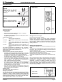
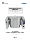
Thermetic
TILTING BOILING PANS, ROUND, ELECTRIC
(GU........,
KU........)
US
OPERATING AND SAFETY INSTRUCTIONS
Doc. 62.9692.01
Edition 1
11.2003
CONTENTS
I
GENERAL INFORMATION ......................................................................... 3
1.
INSTRUCTIONS FOR SAFETY AND USE ......................................................................... 3
1.1
INSTALLATION AND INITIAL OPERATION ....................................................................................3
1.2
OWNER'S OBLIGATIONS ................................................................................................................3
1.3
USE AS PRESCRIBED .....................................................................................................................3
1.4
SAFETY-CONSCIOUS WORKING ...................................................................................................3
1.5
AFTER-SALES SERVICE AND REPAIR ..........................................................................................3
2.
TECHNICAL DATA ............................................................................................................. 4
3.
PACKAGING ....................................................................................................................... 4
4.
TESTS / CERTIFICATES .................................................................................................... 4
5.
SPECIFICATION PLATE .................................................................................................... 4
6.
SERIAL NUMBER YWWXXXXX ......................................................................................... 4
7.
FURTHER DOCUMENTS ................................................................................................... 5
Doc. 62.9692.01
Page 1
II
OPERATING INSTRUCTIONS ....................................................................6
1.
DESCRIPTION .................................................................................................................... 6
2.
INITIAL COMMISSIONING ................................................................................................. 6
3.
STANDBY ........................................................................................................................... 6
4.
AUTOMATIC CONTROL .................................................................................................... 6
4.1
Setting the clock ..............................................................................................................................6
4.2
Starting ..............................................................................................................................................6
4.3
Automatic cooking ...........................................................................................................................7
4.4
Temperature and power settings ....................................................................................................7
4.5
Shutting down ..................................................................................................................................8
4.6
Additional functions ........................................................................................................................8
4.7
Altering the pan settings .................................................................................................................9
4.8
Tilting ................................................................................................................................................9
4.9
Switching off .....................................................................................................................................9
4.10
Power failure .....................................................................................................................................9
4.11
Cooking and chilling with a CHILLTHERM ....................................................................................9
5.
STIRRING SYSTEM .......................................................................................................... 11
6.
ADDITIONAL EQUIPMENT (optional)............................................................................. 13
7.
CLEANING ........................................................................................................................ 13
8.
TROUBLESHOOTING ...................................................................................................... 13
9.
TREATMENT OF COMMERCIAL KITCHEN APPLIANCES ............................................ 14
Page 2
Doc. 62.9692.01
GENERAL INFORMATION
I.
GENERAL INFORMATION
1.
INSTRUCTIONS FOR SAFETY AND USE
1.1
INSTALLATION AND INITIAL OPERATION
S To avoid damage to the appliance, do not let
S The installation, adjustment and initial opera-
tion of the appliance must be carried out
according to the manufacturer's instructions
and only by an authorised specialist.
S Installations for the supply of electricity and
gas must be carried out by approved specialists in compliance with specific national and
local regulations. They bear the responsibility.
S The appliance must not be placed in operation until the user has become familiar with its
operation. The operating instructions and the
related safety precautions must be followed
precisely. Follow strictly the attention and
warning label indications on the appliances.
S
S
S
S
S
1.2
OWNER'S OBLIGATIONS
S The manager is responsible for ensuring that
all components relevant for safety are in perfect working order at all times. The operating
condition of these components must be examined by an authorized technician at least once
a year and any defects remedied if required.
S If the safety valve in the boiler blows off, aftersales service must be requested without
delay to establish the cause and remedy it.
S
S
S
S
1.3
USE AS PRESCRIBED
S The appliance must only be used for cooking
S
S
S
S
S
S
1.4
food in commercial kitchens. The appliance
has only been approved for supervised operation by trained persons.
Closed containers (jars, cans, bottles, tubes,
etc.) must not be heated owing to the danger
of bursting and injuries.
The appliance must not be filled above the
level mark 4 cm below the boiler rim.
Depending on the type of food to be cooked,
filling must be less so as to prevent bubbling
over.
The stirrer is only to be operated with the lid
closed.
The stirrer may be used no more than 3
hours under heaviest load (e.g. mashed
potatoes).
During operation, no objects are to be placed
on the lid
The safety valve on the outer jacket of the
boiling pan must not be actuated by operators (lifting or turning the cap) because hot
steam is released, causing injuries.
S
1.5
S
S
S Devices on wheels set up in block configura-
62.9692.01
AFTER-SALES SERVICE AND REPAIR
S Boiling pans of this design and operating
SAFETY-CONSCIOUS WORKING
tion must be checked before each start-up
whether the potential equalization is connected with the neighbour equipment. The
connection may be done only by authorized
technical personnel.
S Spraying the appliance or parts of it with a
high-pressure cleaning device may cause
malfunctions and is not to be done.
water flow from the mixer tap onto the cooking plates.
When putting oil, fat, water or ingredients in
the preheated hot boiler, they may splash danger of burning!
Always use the handle to open the cover.
Note that while doing so, hot air or steam
may flow out or hot fat may spit out - danger
of burning!
Keep your distance from the lid closing area
when closing the lid - danger of injury!
To avoid damage to the appliance the mixer
tap outlet must be to the front before the lid is
opened or closed.
Cold food is not to be added to the unit for
retherminalization while hot food is operating
in a hot food holding mode.
Take care when turning on the drain tap.
Depending on the food to be cooked, the
drain stream can have varied behaviour and
Keep your distance when passing or driving
by with a truck. The drain cock sticks out.
Tilting is only to be carried out slowly to avoid
the contents spilling over the rim.
Hot steam can be expelled on opening the
lid. Staff must take appropriate measures
(stand well back) to avoid injuries.
Appliances on wheels must be fastened with
the wall.
The area around the tilting boiling pan must
be kept free. Tilting is only to take place with
the lid fully open. - danger of burning!
S
S
mode do not require special acceptance
tests. They are subjected to a pressure and
operating test which meets the regulations on
the manufacturer's premises. Recurrent
pressure testing is not compulsory. To ensure
the complete operating efficiency and safety
of appliances, however, owners should
arrange for personnel authorised by the manufacturer to check on all safety equipment
and to conduct pressure tests at regular
intervals.
In the event of a permanent fault which interferes with operation, the appliance must be
switched off and disconnected from the
power supply.
Repair, maintenance work and other adjustments are only to be carried out by an authorized specialist. The valid local and national
regulations must be observed. This applies
especially to burners, ignition, safety and control elements. Parts requiring replacement are
only to be replaced by original spare parts.
Periodic tests for gas leaks must be carried
out. A service contract is recommended.
Cleaning and maintenance must be done only
when the heating surfaces are cold. Do not
use inflammable liquids to clean the appliance.
An obligatory service check is required
annually.
Page 3
GENERAL INFORMATION
2.
TECHNICAL DATA
PNC
Appliances
Appliance type
Width Feet,
Depth Wheel
Height Height
mm
Electr. Net Boiler
Power weight size
kW
kg
18.2
195
280
9CHG583390
9CHG583246
9CHG583247
9CHG583248
GU1HOEOOOO
GU2HOEOOOO
GU3HOEOOOO
GU4HOEOOOO
270
320
9CHG583249
9CHG583250
9CHG583251
GU2HOEWOOO
GU3HOEWOOO
GU4HOEWOOO
360
9CHG583252
9CHG583253
9CHG583254
GU2HOEOOOZ
GU3HOEOOOZ
GU4HOEOOOZ
9CHG583391
9CHG583255
9CHG583256
9CHG583257
KU1JOEOOOO
KUWJOEOOOO
KUXJOEOOOO
KUYJOEOOOO
410
9CHG583258
9CHG583259
9CHG583260
KUWJOEWOOO
KUXJOEWOOO
KUYJOEWOOO
390
9CHG583261
9CHG583262
9CHG583263
KUWJOEOOOZ
KUXJOEOOOZ
KUYJOEOOOZ
410
9CHG583392
9CHG583264
9CHG583265
9CHG583266
KU1KOEOOOO
KU2KOEOOOO
KU3KOEOOOO
KU4KOEOOOO
390
9CHG583267
9CHG583268
9CHG583269
KU2KOEWOOO
KU3KOEWOOO
KU4KOEWOOO
9CHG583270
9CHG583271
9CHG583272
KU2KOEOOOZ
KU3KOEOOOZ
KU4KOEOOOZ
9CHG583393
9CHG583273
9CHG583274
9CHG583275
KU1LOEOOOO
KU2LOEOOOO
KU3LOEOOOO
KU4LOEOOOO
280
9CHG582565
9CHG582566
9CHG582567
GUWHOEOOOO
GUXHOEOOOO
GUYHOEOOOO
270
9CHG582568
9CHG582569
9CHG582570
GUWHOEWOOO
GUXHOEWOOO
GUYHOEWOOO
9CHG582571
9CHG582572
9CHG582573
GUWHOEOOOZ
GUXHOEOOOZ
GUYHOEOOOZ
9CHG582574
9CHG582575
9CHG582576
KUWJOEOOOO
KUXJOEOOOO
KUYJOEOOOO
9CHG582577
9CHG582578
9CHG582579
KUWJOEWOOO
KUXJOEWOOO
KUYJOEWOOO
9CHG582580
9CHG582581
9CHG582582
KUWJOEOOOZ
KUXJOEOOOZ
KUYJOEOOOZ
9CHG582583
9CHG582584
9CHG582585
KUWKOEOOOO
KUXKOEOOOO
KUYKOEOOOO
9CHG582586
9CHG582587
9CHG582588
KUWKOEWOOO
KUXKOEWOOO
KUYKOEWOOO
9CHG582589
9CHG582590
9CHG582591
KUWKOEOOOZ
KUXKOEOOOZ
KUYKOEOOOZ
9CHG582592
9CHG582593
9CHG582594
KUWLOEOOOO
KUXLOEOOOO
KUYLOEOOOO
270
310
100
(26.4)
150
(39.4)
200
36.2
400
430
200
(52.8)
300
(79.3)
440
1500
900
700
48.2
80
(21.1
GU2EOEOOOZ
GU3EOEOOOZ
GU4EOEOOOZ
GUWEOEOOOZ
GUXEOEOOOZ
GUYEOEOOOZ
1500
900
700
195
9CHG583243
9CHG583244
9CHG583245
9CHG582562
9CHG582563
9CHG582564
30.2
40
GU2EOEWOOO
GU3EOEWOOO
GU4EOEWOOO
GUWEOEWOOO
GUXEOEWOOO
GUYEOEWOOO
1400
900
700
lt.
9CHG583240
9CHG583241
9CHG583242
9CHG582559
9CHG582560
9CHG582561
80
(21.1)
230
24.2
kg
GU1EOEOOOO
GU2EOEOOOO
GU3EOEOOOO
GU4EOEOOOO
GUWEOEOOOO
GUXEOEOOOO
GUYEOEOOOO
1300
900
700
kg/h
0.8bar
9CHG583389
9CHG582601
9CHG582602
9CHG583239
9CHG582469
9CHG582470
9CHG582558
18.2
mm
Steam Net Boiler
Power weight size
GU1COEOOOO
GU2COEOOOO
GU3COEOOOO
GU4COEOOOO
GUWCOEOOOO
GUXCOEOOOO
GUYCOEOOOO
1200
900
700
Appliance type
Width Feet,
Depth Wheel
Height Height
9CHG583388
9CHG582595
9CHG582596
9CHG582597
9CHG582431
9CHG582464
9CHG582465
1200
900
700
lt.
(gal)
PNC
Appliances
420
400
(105.7)
3.
1200
900
700
230
1200
900
700
48
1300
900
700
63
270
310
100
(26.4)
150
(39.4)
320
200
360
1400
900
700
1500
900
700
77
100
400
430
200
(52.8)
300
(79.3)
440
1500
900
700
122
420
400
(105.7)
PACKAGING
All the packaging materials used are environmentally friendly.
They may burnt at an incineration plant or sent for recycling.
4.
TESTS / CERTIFICATES
All electrical appliances are UL 197 and NSF/ANSI 4-2002 and
NSF/ANSI 8-2002 tested. Appliances with Chilltherm are
NSF/ANSI 7-2001 tested.
The appliance noise level is negligible. The statutory guidelines
are fulfilled; the sound pressure level is less than 70 dB (A).
5.
SPECIFICATION PLATE
The specification plate (E) is located in each case inside and
outside on the right of the control panel (C).
6.
SERIAL NUMBER YWWXXXXX
The serial number of the appliance is marked on the type
plate. The 8 digits give following information:
Y
last digit of the year of production
WW
week of production
XXXXX
running number
62.9692.01
Page 4
GENERAL INFORMATION
7.
•
•
•
•
FURTHER DOCUMENTS
Installation instruction
Service manual
Wiring diagram
Spare parts list
62.9692.01
Page 5
OPERATING INSTRUCTIONS
II . OPERATING INSTRUCTIONS
1.
DESCRIPTION
The round, tilting boiling pan is suitable to cook, saute, poach
or steam all kinds of produce. The appliance is floor mounted
on the two brackets or wall mounted on brackets and crossbeams.
The produce is uniformly heated in the base and side walls of
the boiling pan by steam or hot water by an external jacket.
The appliance is totally constructed externally and internally of
corrosion-resistant chrome nickel steel. The inner pan in which
the food is contained is of chromium-nickel-molybdenium
steel. The lid, mounted on the cross-beam is counterbalanced
by a special hinge, i.e. it remains open in all positions set
higher than 15° and closes at positions set at less than 15°.
A precise, state-of-the-art electronic microprocessor control
system with digital preselection of temperature, cooking time
and starting time ensures perfect adherence to the pre-programmed cooking functions.
Appliances fitted with direct steam or hot-water heating can
also be fitted with manual control over the power supply.
a
b
c
d
e
g
h
k
Handle
Lid
Mixer unit with
swivel outlet
Cooking compartment
Pressure
safety valvef
Control panel
Discharge tap
(optional)
Support or wall
console
Pouring lip
Fig. 1
2.
Construction
INITIAL COMMISSIONING
The jacket is filled by the works with demineralised water. All
pan models are supplied ready for use. Thoroughly wash out
the cooking compartment with soapy water, rinse with fresh
water and allow to dry. The appliance should then be heated
for approx. 30 min. at a temperature setting of 100 deg.C.
3.
STANDBY
Check each time before use
The (optional) safety discharge tap must be correctly installed
and closed. Operating elements and pressure gauge must not
be damaged
Filling with produce
Fill with water via mixer unit or hose. The compartment must
not be filled beyond the maximum capacity mark, 4 cm below
the rim. If necessary and dependent on the food being cooked,
a smaller amount of food must be used to prevent bubbling
over.
Salt is only to be added in dissolved form. It must not be added
to an empty pan. Use only a wood or plastic spatula for stirring.
After filling with liquid produce, the appliance can be switched
on. The lid should be kept closed during heating to reduce
energy losses and heating time. At full power, the maximum
heating-up times from 20° to 90°C for pans full of water correspond to the values listed below. Heating-up times are
reduced when pans are only partially filled; when the pan is
only half full, the heating-up time is reduced to approx. 65%.
The heating up times are lower or identical to those for the fast
cooking boiling pans. Whilst full power is required for initial
heating, this is not the case for further cooking. The power
requirements for cooking with lid open is many times that with
the lid closed. The lid should therefore always remain closed
during cooking.
Pan type
Electric
Steam
direct steam
electrical
0,8 bar (11.6psi),
118°C (118°C)
Heating up times in minutes
Heating
Capacity
litres
80
100
150
200
300
400
gal
21.1
26.4
39.4
52.8
79.3
105.7
24
30
34
36
45
46
19
21
23
26
30
33
0.8 bar (5.8 psi), overpressure, temperature 244°F (118°C)
4.
AUTOMATIC CONTROL
The automatic controls can be fitted with more or fewer functions.
The following instructions explain all the possible functions.
4.1
Setting the clock
The clock time is shown on the display (AZ).
Switch on the power isolator (H) (only available as an option)
and the control system switch (S) by turning them from position 0 to I.
0 = Off
I = on
Then press and hold down buttons (ZT) and (Q).After the second acoustic signal, the clock time can be set by turning the
knob (Z).
Turn right = increase
Turn left = reduction
Smallest change = 1 minute
After the time has been set, the buttons (ZT) and (Q) can be
released again.
4.2
Starting
The pan must be in the horizontal position prior to starting, or
the power supply must be disconnected.
Switch on the power isolator (H) (only available as an option).
Turn from position 0 to I.
0 = Off
I = on
H Switch on the power isolator
(only available as an option)
Heating up times
Fig. 2
62.9692.01
Right-hand console (at the bottom)
Page 6
OPERATING INSTRUCTIONS
4.3
Automatic cooking
TT
LT
DT
LD
ZT
LZ
LR
Q
R
LS
Button, activation of settings
Lamp, cooking temperature
Button, cooking time
Lamp, cooking time expires
Button, starting time
Lamp, starting time
Lamp, soft settings
Button, acoustic signal
Button, soft
Lamp, temperature
pre-setting
AT Display, cooking temperature
T Temperature selection knob
AD Display, remaining cooking
time
D Cooking time knob
AZ Display, time
Z Starting time knob
LU
LC
C
U
S Control switch
Fig. 3
Right console
Switching on
Switch on the control switch (S) turn from position 0 to I. This
switches on the temperature pre-setting function. The lamp
(LS) lights up.
0 = Off
I = on
Set the desired cooking temperature (flashing nominal
value) with the temperature selection knob (T) on the display
(AT).
Turn right = increase
Turn left = reduction
Smallest change = 1°C
Programming the cooking time and the starting time (or
only one function).
Pressing the button (DT) switches on the programme for the
cooking time (flashing nominal value). The desired cooking
time is set with the cooking time knob (D) on the display (AD).
Turn right = increase
Turn left = reduction
Smallest change = 1 minute
The lamp (LD) only lights up when the desired temperature
has been reached and the cooking time expires.
Pressing the button (ZT) switches on the programme for the
starting point (flashing nominal value). Set the desired starting
time with the starting time knob (Z) on the display (AZ)
Turn right = increase
Turn left = reduction
Smallest change = 1 minute
The acoustic signal will sound three times and the lamp (LZ)
will light up when the starting time has been reached.
The following pre-programmed nominal functions
Cooking temperature
Cooking time
Starting time
are all activated by pressing the button (TT).
The following displays
Cooking temperature (AT)
Remaining cooking time (AD)
62.9692.01
Clock time (AZ)
indicate the current value.
The lamp (LT) will continue to flash until the nominal cooking
temperature is reached. It then stays on permanently.
4.4
Temperature and power settings
Temperature setting
If the nominal temperature set on the display (AT) is below the
boiling point of water (26 - 212°F (97 - 100°C)), this temperature will be attained during heating up and then maintained at
this value by the electronic controls and the careful supply of
energy. The nominal temperature is not exceeded in this process.
When certain foods with poor conductivity are heated, such as
sugar solutions, nominal temperature settings between 212
and 230°F (100 - 110°C) are required in order to achieve boiling. The correct setting is largely a matter of experience.
Power setting
Fixed power settings can also be programmed in using the
electronic controller. In this case, the pre-set energy is supplied to the food after boiling point has been reached. Setting
the controller to fixed power settings is done in order to enter
the degree of boiling in the food individually, i.e. dependent on
the type of food, the amount of food, the position of the lid, etc.
The following fixed power settings can be entered on the display (AT):
Setting (AT)
Power %
L1
6
L2
12
L3
25
L4
37
L5
50
L6
62
L7
75
L8
87
L9
100
HOLD setting
The HOLD section is located above the power adjustment L1 L9. The knob (T) is used to set a HOLD temperature between
122°F and 210°F (50 and 99°C).
HOLD temperature set: A three digit display (AT) indicates:
H for Hold,
22 - 85 the temperature between 122 and 185°F
03 -10 the temperature between 203 and 210°F (
Owing to the internal conversion in °C not every value is possible. The following settings are allowed:
Display
H22
H31
H40
H49
H58
H67
H76
H85
H94
H03
H10
Hold-Temperature
°F
122
131
140
149
158
167
176
185
194
203
210
The programmed cooking process then operates as follows:
the food is first heated to simmering temperature (approx.
212°F). When simmering temperature is reached, the energy
supply is switched off. The food cools down and is then kept at
the HOLD temperature that has previously been set.
Page 7
OPERATING INSTRUCTIONS
4.5
Shutting down
TT
LT
DT
LD
ZT
LZ
LR
Q
R
LS
Button, activation of settings
Lamp, cooking temperature
Button, cooking time
Lamp, cooking time expires
Button, starting time
Lamp, starting time
Lamp, soft settings
Button, acoustic signal
Button, soft
Lamp, temperature
pre-setting
AT Display, cooking temperature
T Temperature selection knob
AD Display, remaining cooking
time
D Cooking time knob
AZ Display, time
Z Starting time knob
LU
LC
C
U
S Control switch
Fig. 4
Right console
An acoustic signal sounds when cooking is over. This is
acknowledged by pressing the button (Q).
The power supply is then switched off.
All activated functions are subsequently switched off:
• Press the pre-set temperature button (TT) for some seconds.
Lamp (LT) goes out.
• Press the cooking time button (DT).
Lamp (LD) goes out.
• Press the starting time button (ZT).
Lamp (LZ) goes out.
• Switch off the Soft button (R), if this was activated.
• Switch off the control switch (S).
• Turn from position I to 0. Lamp (LS) goes out.
0 = Off
• Switch off the power isolator (H) (only available as an
option).
• Turn from position I to 0.
0 = Off
After cooking has been completed, the control switch (S) is
switched off.
• Turn from position I to 0.
The lamp (LS) goes out.
0 = Off
Switch off the power isolator (H) (only available as an option).
• Turn from position I to 0.
0 = Off
The appliance can be switched off before cooking has been
completed.
If the function buttons (TT), (DT) and (ZT) are switched on and
switching off is only done by means of the control switch (S),
all the functions and previously set data for temperature, cooking time and starting time remain saved and active when the
switch (S) is turned on again.
If the appliance develops a fault, the electrical switch in the
building must also be switched off.
62.9692.01
4.6
Additional functions
SOFT
Pressing the Soft button (R) adapts the power supply to the
food, i.e. reduces it.The lamp (LR) on the button (R) lights up if
the soft setting has been switched on.The following functions
are activated by pressing button (Q):
1. All displays
• Food temperature (AT)
• Cooking time (AD)
• Starting time (AZ)
flash indicating the nominal value that has been programmed in.
2. Acknowledgement of the acoustic signal when cooking has
been completed.
3. Acknowledgement of error messages (see section 12, Troubleshooting).
ZT
LZ
LR
Q
R
AZ
Z
LU
LC
C
U
Button, starting time
Lamp, starting time
Lamp, soft settings
Button, acoustic signal
Button, soft
Display, time
Starting time knob
Fig. 5
Right console
Cooking using the SOFT setting
Normally (Soft setting deactivated), the food is heated up at
maximum power and in the shortest possible heating-up time.
This method of operation is suited to food with a high water
content and which has good heat conductivity properties.
When maximum power is used to heat them up, viscous, pasty
and difficult to heat food (dairy products) tends to dry out along
the heated surface of the pan, to turn dark and to burn. When
the Soft setting is activated, the heating power is automatically
adapted via the temperature difference to the type of food.
Heating-up times are extended a little although the pre-set
temperature is reached without the food sticking or burning.
CLOCK TIME
Display (AZ) shows the clock time and display (AT) shows the
actual temperature of the pan when the control switch (S)
alone is switched on.
If the energy supply is switched on by the (TT) button, the
actual temperature of the boiling pan is shown on the display
(AT) and the excess pressure in the boiling pan jacket is
shown in bar on the display (AZ). To emphasis the latter, a "P"
is placed in front of the pressure value.
HACCP
Appliances can be optionally equipped with the program-linked
cooking process procedure THERMACAM. Cooking processes can be programmed, analysed, logged and documented
and are thus part of the HACCP system (HACCP = hazard
analysis and critical control points).
• The program system is started by pressing the HACCP
button (C).
• The lamp (LC) lights up.
• The number of the cooking program appears on the display
(AZ): HP 00 to 99.
• The program number can be changed by turning the knob
(Z).
• After setting the desired program, the cooking process is
started by pressing the key (TT).
• The nominal temperature is shown on the display (AT) and
Page 8
OPERATING INSTRUCTIONS
the cooking time appears on the display (AD).
The program-linked cooking process is switched off by
pressing the HACCP button (C). The appliance is then
switched off according to 5.5.
•
A separate set of operating instructions contains information
on the programming, analysing, logging and documenting of
cooking processes using an external computer.
4.7
Altering the pan settings
Altering the nominal values while working
All the nominal values programmed in originally can be easily
altered during the working process by setting the buttons for
temperature (T), for the cooking time (D) and for the starting
time (Z) to the new values. When the buttons are turned, the
nominal value will appear flashing on the relevant display. If
the nominal value is not altered for a few seconds, the display
reverts to the actual value.
Altering the cooking programmes while working
Switching off the button (TT) will interrupt the heating/cooking
process. Switching off the cooking time button (DT) reverts to
continuous cooking. Switching off the starting time button (ZT)
deletes the programmed-in starting time. The appliance can be
started manually.
4.8
Tilting
MECHANICAL TILTING
The boiling pan is tilted with the help of an electric motor. It
only works when the power isolator (H) (only available as an
option) and the control switch (S) are switched on by turning
from position 0 to I.
Lamp (LS) will light up.
Tilting at variable speed by turning the tilting knob (K):
Emptying the pan turn to the right
Tilting back turn to the left
Turning the knob further will accelerate the tilting function.
.
K
Tilting knob
Fig. 6
Left-hand console (at the top)
Tilting is only to be activated with lid fully open and with the
swivel outlet of the water mixing unit in the correct position
(precisely towards the front) and where no object is present
under the appliance in the tilting zone. The boiling pan is tilted
down by turning tilting switch clockwise (to the right) and tilted
up by turning it anticlockwise (to the left). Tilting at variable
speed will only take place as long as the tilting switch (K) is
held in the tilting position. On being released, the switch
returns to the neutral, centre position and due to the drive selflocking, the boiling pan immediately comes to rest, whatever
the position and filling level. The tilting motor is automatically
switched off in the extreme positions of the boiling pan; the
horizontal and fully tilted positions, so any further actuation of
the tilting switch (K) has no effect.
The heating can no longer be operated with even the smallest
degree of tilt from the horizontal.
Select the rate of tilting so that the produce is discharged in the
region of the pouring lip. This is easy to do by varying the tilting
speed. Avoid spillage of the contents over the rim of the boiling
pan.
62.9692.01
4.9
Switching off
The appliance is shut down by turning the power isolator (H)
(available as an option) as well as the control switch (S) to
zero. All lights will go out when this is done.
In the case of faults, the appliance must also be disconnected
from all supply connections (mains supply, steam and hotwater, etc.
4.10
Power failure
The loss of mains electricity while a cooking pan is being used
can result in cooking being halted or interrupted. Cooking staff
are then required to make an additional intervention in the controls or to monitor further processing.
Power failure when:
The measure to be implemented to restart the cooking
process after the mains supply has been restored
The cooking process is taking Press the key (TT)
place
After the mains supply has
The cooking process has been restored, the starting
been programmed with a time comes to an end and the
starting time although this has heating process starts autonot yet expired
matically without any intervention in the controls
4.11
Cooking and chilling with a CHILLTHERM
Manual and automatic control options for cooking and chilling
(or vice versa) in association with an external cooling-water
installation or with water from the mains supply.
To switch on:
Switch on control switch S.
MANUAL CHILLING
Programming the chilling temperature and chilling time
(or only one function)
• The program is activated by pressing button M until lamp
LM lights up (press for approx. 2 seconds).
• Press button M briefly to enter the chilling temperature.
• Use chilling-temperature button T on display AT to set the
desired chilling temperature; a C with the temperature display will flash on display AT.
• Switch on the mixer with switch RS (an intermittent signal
will sound if the mixer is not activated and error A03 will be
displayed).
• All preprogrammed functions are started by pressing button TT.
• Lamp LT will flash until the chilling temperature is reached
and will then stay on permanently; this also applies to chilling-time lamp LD if this has been selected.
• A signal will sound as soon as the chilling temperature is
reached; press button Q to confirm.
• The chilling temperature reached will now be maintained
exactly.
Press button TT to end manual chilling.
COOK & CHILL (automatic cooking and chilling)
Programming cooking and chilling times and their starting time
(if required)
• The cook & chill program is switched on by pressing button
H; lamp LH will light up.
Programming the cooking process:
• Enter the desired cooking temperature using cooking-temperature knob T on display AT.
• Enter the desired cooking time using cooking-time knob D
on display AD; lamps LD and LH will light up.
• The starting time can also be entered as follows:
• Press the button (ZT) and use the starting-time button (Z)
on the display (AZ) to set the desired starting time, the
Page 9
OPERATING INSTRUCTIONS
lamp (LZ) will light up.
Programming the chilling process:
• Press button M briefly. The display AT flashes and a C
appears behind the temperature indication. During this
announcement the cooling temperature can be set.
CHILL temperature set: A three digit display (AT) indicates:
C for Chill,
32 - 95 the temperature between 32 and 95°F
00 - 120 the temperature between 100 and 120°F
Owing to the internal conversion in °C not every value is possible. The following settings are allowed:
Display
C32
C41
C50
C59
C68
C77
C86
C95
C04
C13
C20
Hold-Temperature
°F
32
41
50
59
68
77
86
95
104
113
120
°C
0
5
10
15
20
25
30
35
40
45
49
•
Use chilling-temperature knob T on display AT to set the
desired chilling temperature.
The chilling time can also be entered as follows:
• Press button DT and use chilling-time knob D on display
AD to set the desired chilling-time period.
Start chilling & cooking programming:
• Switch on the mixer with switch RS (an intermittent signal
will sound if the mixer is not activated and error A03 will be
displayed).
• Press button TT
While this process is taking place, each of the currently active
lamps LT and LD will flash for control purposes.
At the predetermined starting time, a signal will sound three
times for control purposes; the predetermined chill & cook
processes will now operate with lamps LT and LD flashing if
previously selected.
• When the cooling temperature has been reached, a signal
will sound until confirmed by pressing button Q.
• The cooling temperature attained is now maintained.
• Now press button TT to end the cooking & chilling process.
62.9692.01
TT
LT
DT
LD
ZT
LZ
LH
LM
M
H
Q
AT
Button, activation of settings
Lamp, cooking temperature
Button, cooking time
Lamp, cooking time expires
Button, starting time
Lamp, starting time
Lamp, program activation
Button, chilling
Display, chilling temperature
T Button, chilling temperature
AD Display, remaining cooking
time
D Cooking time knob
AZ Display, time
Z Starting time knob
LF
F
Fig. 7
Right console
CHILL & COOK (automatic chilling and cooking)
Programming chilling and cooking durations and their
starting time (if required)
• The chill & cook program is switched on by pressing button
F. Lamps LF and LZ will light up.
Programming the chilling process:
• Press button M briefly and use chilling-temperature knob T
on display AT to set the desired chilling temperature as
explained in COOK & CHILL; a C with the temperature display will flash on display AT.
• The starting time can also be entered as follows:
Press button ZT and use starting-time knob Z on display
AZ to set the desired starting time; lamp LZ will light up.
Programming the cooking process:
• Use cooking-temperature knob T on display AT to enter the
desired cooking temperature.
• Use cooking-time knob D on display AD to set the desired
period of cooking; lamp LD will light up.
Start chilling & cooking programming:
• Switch on the mixer with switch RS (an intermittent signal
will sound if the mixer is not activated and error A03 will be
displayed).
• Press button TT
While this process is taking place, each of the currently
active lamps LZ, LT and LD will flash for control purposes if
previously selected.
At the predetermined starting time, a signal will sound
three times for control purposes; the predetermined chill &
cook processes will now operate with lamps LT and LD
flashing if previously selected.
• When the cooking temperature has been reached, a signal
will sound until confirmed by pressing button Q.
• The cooking temperature attained is now maintained.
• Now press button TT to end the chilling & cooking process.
Page 10
OPERATING INSTRUCTIONS
CHILLTHERM (general)
Application
Cooking followed by rapid chilling to 41 - 59°F (5° - 15°C) in
one and the same cooking pan enables the food to be stored
in portions or in larger containers for a lengthy period of time in
a refrigerated store without any loss in hygiene or quality. In
this respect, the cook & chill system can be considered a suitable process for the preparation, planning, economy of use and
transport, etc. of food.
11
14
15
Stirrer
Drive shaft
Clip
Fig. 9
Fig. 8
End of chilling
If the chilling time is also activated in addition to the chilling
temperature, the chilling system will switch off when first
reaching one of the values (chilling temperature or chilling
time) and will keep the predetermined temperature constant
until the appliance is switched off.
Release
At the end of the cooking process, the steam pressure is automatically released from the heating jacket to prevent the cooling aggregate from being subjected to additional heat.
Program changes
The cook can manually override the programmed values at
any time while all processes are taking place.
Mixer
In order to minimize heating and chilling times, the mixer with
its wipers must run during cooking & chilling processes (otherwise the error A03 occurs); only in one direction of rotation with
foods thin in consistency but in alternating directions when
cooking foods that are thick or compact in consistency.
Combined chilling
In the case of sequential chilling, i.e. with mains water in the
upper temperature range of the food and with cold water from
a chilling unit in the lower range, the person in charge of installation must enter certain corresponding parameters in the electronic control system (q.v. installation instructions).
Parameter P36 to 1, P37 to 1, P163 to the desired food temperature in °F at which the changeover from mains water to
cold water is to take place (standard setting is 104°F (40°C)).
5.
Stirring system
Mixer with scrapers
The purpose of the mixer is to mix the food thoroughly to
ensure even cooking. The scrapers are intended to wipe off
any food sticking to the wall of the pan for remixing with the
food. The scrapers are made of POM-C (Polymethylene copolymer) and are approved for use with food.
1
3
2
1
2
3
Mixer
Pan-base scrapper
Side scrapper
Fig. 10 Stirring system
STIRRING SYSTEM
The advantage of the optionally installed stirrer is the achievement of uniform temperatures, effective mixing of the produce
and hence, homogeneous cooking results throughout the boiling pan. By means of scrapers, produce is also removed from
the boiling pan wall, preventing the formation of thicker layers
on the heated surfaces. The stirrer also serves to break up or
puree cooked produce. The boiling pan can be operated with
and without stirrer as required.
Mounting the stirrer
With lid open and power off, the stirrer (11) is placed on the
drive shaft (14) and the square section of the shaft introduced
fully into the square opening of the stirrer. To lock the stirrer,
the clip (15) on the stirrer is placed in a horizontal position and
engages in the two notches in the square section of the shaft
(14).To remove the grid stirrer (11), clip (15) is folded to the
horizontal position on the other side and the stirrer withdrawn
from the shaft (14) upwards.
62.9692.01
Page 11
OPERATING INSTRUCTIONS
Fitting the scrapers
Removal
Push the buttom (1) and pull
simultanously the complete fixation bolt (2). Remove the
scraper (3).
1
RW Stirrer switch
N Stirrer button,
2
3
1
Insertion
Insert the scraper (3). Push the
buttom (1) and push simultaneously the complete fixation bolt
(2).
2
3
Fig. 11 Fitting the scrapers
Operating the stirrer
Starting the stirrer:
• Close the lid
• Place main switch (H), where fitted, to the On position.
• Switch on the control switch (S)
• Set stirrer switch (RW) as required according to the following operating programme:
Position (RW) Function
0
Stirring system switched off.
10 o'clock
Stirrer rotates continuously on same side clockwise.
2 o'clock
Stirrer rotates alternately right and left with a 4
second rest period and a 16 second running
period.
3 o'clock
Stirrer rotates alternately right and left with a 16
second rest period and a 16 second running
period.
The choice of programme is dependent on type of produce.
Step "left" is adequate for very fluid produce; steps "right" are
used for thick produce which is difficult to mix.
Safety measures
Always keep lid closed when operating the stirrer.
• The stirrer remains at rest after a power failure. It can only
be restarted by actuating the stirrer switch (RW), ie. first set
to position 0 and then back to the required programme.
• No objects (eg. mixing spoons, measuring rod, etc.) are to
be placed in the pan whilst the stirrer is running.
• In the event of faults, blockage or the occurrence of unusual noise, the stirrer switch (RW) must be placed immediately to position 0. The stirrer may not be switched on
again until the fault has been remedied.
• If the drive motor is overloaded, the stirrer is switched off
by a thermal cut-out. Switch (RW) is to be immediately
placed to position 0. Further operation of the stirrer is only
possible when the cut-out has cooled.
• If the drive motor is frequently overloaded and cuts out, the
produce is too stiff. Stirring can be maintained by thinning
or by removing part of the produce.
Shutting down
Place stirrer switch (RW) to position 0.
Emergency shutdown
The stirring system can be shut down by pressing the red button (N). The red button will remain depressed until is turned
clockwise. To switch on again, the stirring system switch (RW)
must be turned to position 0 and then reset to the setting of the
desired operating programme. The stirring system will recommence operation after a delay of a few seconds.
62.9692.01
Fig. 12 Left console
Mixing when the lid is open
(only if a lid contact switch is fitted)
During normal operation, the lid limit switch automatically
switches off the mixer if the lid is opened during operation.
However, it is possible to deactivate the lid limit switch temporarily in order to observe or check the food during mixing with
the lid open or if it is necessary to add certain ingredients
evenly to the food.
Bridging the lid limit switch:
The mixer is switched on to a selected operating level. Switch
(RW).
The button (U) on the right-hand console is then pressed and
held down. After 2 seconds, the bridging of the limit switch is
activated with the lid open.
While the button remains held down, an intermittent signal is
heard and the lamp (LU) goes on and off.
Releasing the key (U) will cause the mixer to stop.
Closing the lid again will cause the mixer to recommence operation.
NB: The lid limit switch can be bridged during all the working
programs of the mixer. Please note that the mixer is subject to
interruptions in operation of between 4 and 16 seconds
dependent on program. If bridging is started during one of
these interruptions, it will be necessary to wait with bridging
until the mixer starts again. Working with utensils or reaching
into the pan is absolutely prohibited while the mixer is still
switched on (switch RW).
LR
Q
R
LS
LU Lamp, mixer
C
U Button, mixer
S
Fig. 13 Right console
Page 12
OPERATING INSTRUCTIONS
6.
ADDITIONAL EQUIPMENT (optional)
Strainer
The strainer appropriate for the
size of pan is firmly inserted into
the two retaining clips fitted to
the sides of the pouring lip.
General
Cleaning with steel brushes, wire or copper wool, products
containing sand etc. is to be avoided as such media will
destroy the surface and provide the opportunity for it to be
attacked and start to corrode. Spraying the appliance or its
parts with a water jet or high pressure cleaning equipment is
harmful and can cause malfunctions. Such practice is therefore forbidden. The drain in the cover plate, the bottom grid or
internal drain can be cleaned with a bottle brush.
Measuring rod
The measuring rod with filling
level marking is hung on the top
rim of the pan. The scale has 5
or 10 litre graduation marks.The
measuring rod must not be used
at the same time as the stirrer as
this may result in injury.
Additional equipment, stirrer, strainer etc.
These loose parts are to be cleaned outside the boiling pan.
Where dimensions allow, these can be washed in a suitable
dishwasher.
Desinfection of scrapers:
The srcapers are locked to the stirrer with a bolt, which is
located inside the food zone. These parts must be disinfected
at regular intervals at temperatures above 179.6°F (82°C).
Best is to accomplish the disinfection after every food preparation below 179.6°F (82°C).
8.
Discharge strainer
To prevent blocking the discharge tap when pouring liquids
from the boiling pan, a discharge
strainer (1) can be placed in the
discharge pipe of the boiling pan.
The strainer is fitted and
removed with the aid of a hooked
rod (2).
Strainer for dough dumplings
and scraper
This accessory is for producing
Knoepfli or dough dumplings.
The stainer (1) is hung in the
compartment. The dough (2) is
placed in the strainer. Over the
hot water in the compartment,
the dough is pressed through the
holes in the strainer by moving
the scraper (3) back and forward
to form droplets.
E7
Failure of food temperature sensor
Failure of jacket temperature sensor
Failure of deaeration food
temperature sensor
Failure of control circuit
board temperature sensor
Sensor J15 of produce
temperature too high
Sensor J16 of jacket temperature too high
E8
Jacket pressure too high
E9
Failure of A/D converter
E1
E2
E3
E5
E6
Fig. 14 Accessories
7.
CLEANING
The appliance should be allowed to cool prior to cleaning.
Compartment
With normal use it is sufficient to clean the compartment with
hot water with an added grease solvent. Next, rinse with clean
hot water and dry with a cloth or absorbent paper. There is a
risk of corrosion if water with a high-salt content and/or food
are allowed to dry out in the pan.
Appliance casing
The appliance surfaces are of corrosion-free chrome nickel
steel. They are to be washed down with hot soapy water containing a standard grease solvent cleaning agent and dried off.
E10
E11
E30
E31
62.9692.01
TROUBLESHOOTING
Faults in the appliance are registered by the control electronics
and shown on the display (AT) dependent on the type of fault
by the letters A or E in combination with a double-digit number.
When the fault occurs, an intermittent acoustic signal sounds,
the power supply is interrupted and the lamp is switched off.
Press button (Q) again to acknowledge the error message
(acoustic signal).
Shut down the appliance if a continuous fault that prevents
operation arises (see section 5.5 Shutting down). Summon the
aftersales service to remedy the fault. Until this is done, the
appliance must not be used and must be disconnected from
the mains supply.
Safety thermostat for dry
cycle
protection
has
responded
Sensor of deaeration temperature too high
Summon service
and report reading
Summon service
and report reading
Summon service
and report reading
Summon service
and report reading
Summon service
and report reading
Summon service
and report reading
Summon service
and report reading
Summon service
and report reading
agent
Summon service
and report reading
agent
agent
agent
agent
agent
agent
agent
agent
Summon service agent
and report reading
Remedy the cause of the
breakdown, allow to cool
Stirring drive motor over- off, press button (Q) and
load
restart the stirrer (set
switch (R) at 0 and switch
on again)
Acknowledge the warning
by pressing the button (Q).
The appliance can conAdvance warning: the tinue to be used. The
water in the jacket is due warning is given whenfor topping up
ever the appliance is
reused. Summon service
agent occasionally and
report reading.
Page 13
OPERATING INSTRUCTIONS
9.
TREATMENT OF COMMERCIAL KITCHEN
APPLIANCES
Commercial kitchen appliances are executed in corrosion
resistant chrome nickel steels, material numbers 1.4301 and
1.4404.
The corrosion resistance of these steels is based on a passive
layer formed on the surface with access to atmospheric oxygen. Accelerated formation or reformation of the passivity
occurs by treating surfaces with running water containing oxygen. Aggressive media with a reducing effect (oxygen consuming) such as substances containing hydrochloric acid,
chlorides and seasoning concentrates, mustard, vinegar
essence, seasoning or spice tablets, salt solutions, etc.,
depending on concentration and temperature, can result in
chemical damage or the destruction of the passive layer. Damage can also result from foreign rust (iron particles) due to the
formation of galvanic elements and lack of oxygen (no air
access or low oxygen water).
Therefore the following principles should be observed when
working with high grade steel equipment:
1. Surfaces of equipment of corrosion resistant steel are
always to be kept clean and exposed to the air. Remove covers from utensils when not in use to provide free air access.
Regularly remove limescale, grease, starch and egg white
deposits by cleaning. Corrosion can occur under these layers
due to the absence of air exposure. Limescale can be
removed with 10% acetic acid, 10% phosphoric acid or with
suitable limescale removers available on the market.
2. Corrosion resistant steel objects must not be kept in longterm contact with acids, spices and seasonings, salt, etc. Also
promoters of corrosion are acid vapours as produced during
floor cleaning. Contact surfaces are to be rinsed off with fresh
water. This applies after use, especially after cooking potatoes, noodles, rice etc. in salt water. Dried-on cooking water
residues form high concentration salt solutions which can
cause point corrosion. So, immediately after use, rinse cooking
utensils in fresh water or keep filled with cold water to cool
them. It is not advisable to use one utensil exclusively for cooking e.g. potatoes in salt water. For stainless steel it is beneficial
to use utensils for different produce, e.g. for soups containing
fat or acid-containing vegetables (such as sauerkraut, for
example).
3. Stainless steel surfaces should, where possible, be protected from mechanical damage, especially from other metals.
Corrosion can occur if stainless steel comes into contact with
iron (steel wool, chips from pipes, water containing iron). New
corrosion locations can be removed with a mild abrasive or
fine emery cloth. Heavier corrosion can be washed off with a
warm 2-5% solution of oxalic acid. Treatment with 10% nitric
acid is necessary if this proves ineffectual. Due to the associated hazards, this type of cleaning is only to be carried out by
suitably trained staff in compliance with the valid regulations.
4. No bleaching or chlorine-containing cleaning agents are to
be used for cleaning. Utensils are to be thoroughly rinsed with
water and dried after cleaning. The surfaces of appliances are
of corrosion resistant chrome nickel steel. They are to be
washed down with hot soapy water with the addition of a
standard grease solvent. Avoid cleaning with steel brushes,
steel wool, copper scouring pads or cloths, products containing sand, etc. as such media destroy the surfaces and create
the conditions for corrosion formation. Spraying appliances or
parts of appliances with a water jet or high pressure cleaning
equipment is harmful and can cause malfunction. This is therefore prohibited.
Note:
The type and concentration of solvents used for cleaning the
surfaces must comply with the code of the Federal Regulations
21 CFR Part 178.1010.
62.9692.01
Page 14