1
D
SHOP MANUAL
NHSOaeroBO
� HONDA
�
NH80
CONTENTS
HOW TO USE THIS MANUAL
GENERAL INFORMATION
Follow the Maintenance Schedule (Section 3) re
commendations to ensure that the vehicle is in
peak operating condition and the emission levels
are withir. the standards set by the U.S. Environ
mental Protection Agency. Performing the first
scheduled maintenance is very important. It com
pensates for the initial wear that occurs during
the break-in period.
LUBRICATION
MAINTENANCE
FUEL SYSTEM
Sections 1 through 3 apply to the whole motor
scooter, while sections 4 through 16 describe
parts of the scooter, grouped according to loca
tion.
ENGINE REMOVAL/INSTALLATION
CYLINDER HEAD/CYLINDER/PISTON
w
2
Find the section you want on this page, then turn
to the table of contents on page 1 of that section.
(!)
2
w
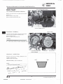
Most sections start with an assembly or system
illustration, service information and trouble
shooting for the section. The subsequent pages
give detailed procedures.
If you are familiar with this scooter read the
TECHNICAL F EATU R E S in section 16.
I f you don't know what the source of the trouble
is, refer to section 18, Troubleshooting.
ALTERNATOR
DRIVE AND DRIVEN PULLEYS/
KICK STARTER/CLUTCH
FINAL REDUCTION
CRANKCASE/CRANKSHAFT
�==:!====-===:==
FRAME COVERS
STEERING/FRONT WHEEL/
BRAKE/SUSPENSION
REAR WHEEL/BRAKE/SUSPENSION
FUEL TANK/OIL TANK
ELECTRICAL EQUIPMENT
A L L I N F O R MATION, I L LUSTRATIONS, D I
RECTIONS A N D SPECIF ICATIONS INCLUD
ED IN THIS P U B L I CATION ARE BASED ON
T H E LATEST P R O D UCT I N F O RMATION
AVAILABLE AT THE TIME OF APPROVAL
FOR P R I NT I N G . HONDA MOTOR CO.,
LTD. RESERVES THE R I G H T TO MAKE
CHANGES AT ANY TIME WITHOUT NO
TICE A N D WITHOUT I N C U R R I N G ANY
OBLIGATION WHATEVER.
NO PART OF T H I S PUBLICATION MAY BE
REPRODUCED WITHOUT W R I TTEN P E R
M I SSION.
WIRING DIAGRAM
TECHNICAL FEATURES
TROUBLESHOOTING
HONDA MOTOR CO., LTD.
Service Publications Office
Date of Issue: May, 1983
© HONDA MOTOR CO., LTO.
1
HONDA
NHSO
1 . GENERAL INFORMATION
1-6
SERVICE RULES
1-1
TOOLS
MODEL IDENTIFICATION
1-2
SPECIFICATIONS
1- 3
EXHAUST AND NOISE EMISSION
CONTROL SYSTEMS (U.S.A. ONLY) 1-10
TORQUE VALUES
1-5
GENERAL SAFETY
1-1
CABLE & HARNESS ROUTING
EMISSION CONTROL
INFORMATION LABEL
1-7
1-10
GENERAL SAFETY
tid·hhllftfj
If the engine must be rwming to do some work, make
sure rhe area is we/1-venrilated. Never run rhe engine
your eyes, skin and clothing. In case of contacr, flush
in a closed area.
thoroughly wirh warer and call a docror if elecrrolyre
The ballery electrolyre contains sulfuric acid. Rrolect
The exhausr conrains poisonous
carbon monoxide gas.
gers in your eyes.
The bauery generates hydrogen gas which can be
Gasoline is exrremely flammable and is explosi11e
under cerrain conditions. Do not smoke or allow
highly explosive. Do nor smoke or allow flames or
flames or sparks in your working area.
sparks near the bauery, especially while charging ir.
SERVICE RULES
1. Use genuine HONDA or HONDA·recommended parts and lubricants or their equivalents. Parts that do not meet HONDA's
design specifications may damage the scooter.
2. Use the special tools designed for this product.
3. Use only metric tools when servicing this scooter. Metric bolts, nuts, and screws are not interchangeable with English
fasteners. The use of incorrect tools and fasteners may damage the scooter.
4. Install new gaskets, O·rings, cotter pins, lock plates, etc. when reassembling.
5. When tightening bolts or nuts, begin with larger·diameter or inner bolts first, and tighten to the specified torque diagonally
in 2-3 steps, unless a particular sequence is specified.
6. Clean parts in non·flammable or high flash point solvent upon disassembly. Lubricate any sliding surfaces before reassem·
bly.
7. After reassembly, check all parts for proper installation and operation.
8. Route all electrical wires as shown on page 1·7 Cable and Harness Routing and always away from sharp edges and areas
where they might be pinched between moving parts.
Date of Issue: May, 1983
©HONDA MOTOR CO., LTD.
3
1 -1
Ill
� HONDA
�
GENERAL INFORMATION
NHSO
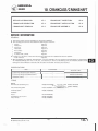
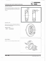
The vehicle identification number is on the frame pipe of
the center of the front cover.
MODEL IDENTIFICATION
-
Beginning Frame Number: H F 01 0* DS000001
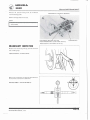
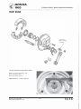
The carburetor identification number is on the left side of
the carburetor body.
The frame serial number is stamped on the left side of the
frame body.
_
_...
_ ...,.,.
.
The engine serial number is stamped on the back of the
crankcase near the rear wheel.
1 -2
The color label is attached to the left side of the fuel tank,
under the seat.
4
Date of Issue: May,
1983
©HONDA MOTOR CO.,
LTO.
� HONDA
�
GENERAL INFORMATION
NHSO
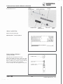
SPECIFICATIONS
ITEM
SPECIFICATIONS
DIMENSIONS
Overall length
Overall width
Overall height
Wheelbase
Seat height
Foot peg height
Ground clearance
Dry weight
Curb weight
1 ,685 mm (66.3 in}
665 mm !26.2 in}
1 ,0 70 mm (42.1 in)
1 , 1 70 mm (46. 1 in}
730 mm (28. 7 in}
256 mm ( 1 0 . 1 in)
1 1 0 mm (4.3 in)
75 kg ( 1 6 5 lb)
80 kg ( 1 76 lb)
FRAME
Type
Front suspension, travel
Rear suspension, travel
Gross vehicle weight rating, '83:
'84:
Vehicle capacity load, '83:
'84:
Front tire size
Rear tire size
Back bone
Bottom link, 8 1 mm (3. 1 9 in}
Engine/Final drive unit swingarm, 78 mm (3.07 in)
222 kg (490 lb)
232 kg (505 lb)
1 45 kg (320 lb)
1 50 kg (330 lb)
3.50-1 0-4PR
3.50-10-4PR
Cold tire
pressure
ENGINE
Up to 9 0 kg
(200 lbs) load
Front
21 psi ( 1 50 kPa, 1 . 5 kg/em•)
Rear
24 psi ( 1 7 5 kPa. 1 .7 5 kg/cm2)
Up to vehicle
capacity load
Front
2 1 psi ( 1 50 kPa, 1 . 5 kg/cm2}
Rear
36 psi (250 kPa, 2.5 kg/cm2)
Front brake, lining swept area
Rear brake, lining swept area
Fuel capacity
Fuel reserve capacity
Caster
Trail
Internal expanding shoe, 86 cm2 ( 1 3.4 sq in)
Internal expanding shoe, 60 cm2 (9 .3 sq in)
5.3 liters ( 1 .4 US gal}
0.9 liters !0.25 US gal}
63 °
70 mm (2.8 in)
Type
Cylinder arrangement
Bore and stroke
Displacement
Compression ratio
Maximum horsepower
Maximum torque
Transmission oil capacity
Oil tank capacity
Lubrication system
Air filtration
Cylinder compression
Port timing Intake
Open
Close
Exhaust
Open
Close
Scavenge Open
Close
Engine dry weight
Idle speed
Air cooled 2-stroke
Single cylinder 1 5 ° inclined from vertical
48 x 4 4 mm ( 1 .89 x 1 .73 in)
80 cm3 (4.88 cu in}
6.8 : 1
5 BHP/5,000 rpm
0.82 kg-m (5.9 ft-lbl/3,500 rpm
90 cc (0.09 us qt)
1 .3 liters ( 1 .4 US qt)
Lubricated by mixing oil with fuel
Oiled urethane foam
1 0. 0 - 1 4.0 kg/cm2 ( 1 42-200 psi)
Reed valve controlled
Reed valve controlled
80° BBDC
80° ABDC
55 ° BBDC
55 ° ABDC
18 kg (39.7 lb)
1,800 ± 1 0 0 rpm
Date of Issue: November, 1983
© American Honda Motor Co., Inc. 1983 - All
Rights Reserved
5
1 -3
.
.
HONDA
GENERAL INFORMATION
NH80
SPECIFICATION
ITEM
CARBURETION
Carburetor type, size
Identification number
Air screw
Float level
Piston valve, 16 mm (0.63 in) venturi dia.
PB540
Refer to page 4·1 0
8.5 mm (0.33 in)
DRIVE TRAIN
Clutch type
Primary reduction
Gear ratio
Final reduction
Automatic dry centrifugal clutch
V-belt
2.3-1.2 : 1
6.914 : 1
ELECTRICAL
Ignition type
Ignition timing "F" mark
Starting system
Alternator
Battery capacity
C.D.I.
1 4° BTDC at idle
Starting motor and k ickstarter
12V-11 OW/5,000 rpm
12V-5AH
Spark plug
LIGHTS
1 -4
-------
NGK
NO
Standard
BPR6HS
W20FPR
For cold climate,
(Below 5°C, 41°F)
BPR5HS
W16FPR
For extended
high speed riding
BPR7HS
W22FPR
Spark plug gap
Fuse capacity
0.6-0.7 mm (0.024-0.028 in)
7A
Headlight (High/Low)
Tail/brake light
Turn signals
(Front)
(Rear)
Speedometer light
Oil indicator light
Turn signal indicator
High beam indicator
12V-25/25W
12V-3/32 cp
12V-32 cp
12V-32 cp
12V-2 cp
12V-2 cp
12V-2 cp
12V-2 cp
6
SAE No. 1 157
SAE No. 1 156
SAE No. 1 1 56
SAE No. 57
SAE No. 57
SAE No. 57
SAE No. 57
Date of Issue: May, 1 983
© HONDA MOTOR CO., LTO.
� HONDA
�
NHSO
GENERAL INFORMATION
TORQUE VALUES
ENGINE
ITEM
I
TORQUE
N ·m (kg-m, ft-lb)
THREAD DIA.
mm
6
10
10
10
6
6
6
Cylinder head
Flywheel
Drive pulley
Clutch outer
Driven face and clutch
Intake pipe
Carburetor
Crankcase
8-12
35-40
35-40
35-40
35-40
8-12
9-12
8-12
(0.8-1.2, 6-9)
(3.5-4.0, 25-29)
(3.5-4.0, 25-29)
(3.5-4.0, 25-29)
( 3.5-4.0, 25-29)
(0.8-1.2, 6-9)
(0.9-1.2, 7-9)
(0.8-1.2, 6-9)
REMARKS
�hile the engine is cold (below
T 35°C, 95° F).
FRAME
ITEM
TORQUE
N-m (kg-m, ft·lb)
THREAD DIA.
mm
Steering stem nut
Front axle nut
Engine hanger bolt
Rear axle nut
Rear shock absorber
(Upper)
Rear shock absorber
( Lower)
Rear shock absorber
damper lock nut
Rear brake arm
Kick starter pedal
Front brake arm
Front fork pivot arm
Muffler
12
10
14
80-120
50-70
27-33
80-100
(8.0-1 2.0, 58-87)
(5.0-7.0, 36-5 1 )
(2.7-3.3, 20-24)
(8.0-1 0.0, 58-72)
10
30-40
(3.0-4.0, 22-29)
8
20-30
(2.0-3.0, 14-22)
8
1 5-25
( 1 .5-2.5, 1 1 - 1 8)
5
6
6
8
8
4-7
8-10
8-12
20-24
40-50
(0.4-0.7, 3-5)
(0.8-1.0, 6-7)
(0.8-1.2, 6-9)
(2.0-2.4, 14-17)
(4.0-5.0, 29-36)
REMARKS
Self-locking nut
Self-locking nut
Self-locking nut
Apply a locking agent.
Torque specifications listed above are for important fasteners. Others should be tightened to the standard torque values below.
STANDARD TORQUE VALUES
ITEM
5 mm bolt and nut
6 mm bolt and nut
8 mm bolt and nut
1 0 mm bolt and nut
1 2 mm bolt and nut
Date of Issue: May, 1 983
© HONDA MOTOR CO., LTD.
TORQUE N-m (kg-m, ft·lb)
ITEM
4- 6 (0.4-0.6, 3-4)
8-12 (0.8-1.2, 6-9)
1 8-25 ( 1 .8-2.5, 1 3-18)
30-40 (3.0-4.0, 22-29)
50-60 (5.0-6.0, 36-43)
5 mm screw
6 mm screw
6 mm flange bolt and nut
8 mm flange bolt and nut
1 0 mm flange bolt and nut
7
TORQUE N·m (kg·m, ft·lb)
3- 5 (0.3-0.5, 3-4)
7-11 (0.7-1 . 1 , 5-8)
10-14 ( 1 .0-1.4, 7-10)
20-30 (2.0-3.0, 14-22)
30-40 (3.0-4.0, 22-29)
1 -5
� HONDA
� NHSO
GENERAL INFORMATION
TOOLS
SPECIAL
DESCRIPTION
NUMBER
Clutch spring compressor
Seal and case assembling tool
07960-KJ90000
07965·GC70000
Bearing driver
Spring attachment holder
Lock nut wrench, 39 mm
·Universal bearing puller
Crankcase puller
Bearing remover set, 1 2 mm
07945-GC80000
07967-GCSOOOO
07916-1870001
07631 ·001 0000
07935-KG80000
07936-1660001
*Bearing remover, 1 5 mm
Hand vacuum pump
Rear shock absorber
attachment A
Bearing driver attachment,
28 x 30 mm
07936-KC1 0000
ST·AH·260-MC7
•
•
L
ALTERNATIVE
NUMBER
Assembly collar
Assembly tool (bolt only)
07965-GC701 00
07965-1480200
Spring attachment holder
07967·1 1 801 00
Bearing remover. 1 2 mm
07936-1 660100
07936-37 1 0200
L Remover weight
(U.S.A. only)
07967-GA701 01
1 07946-18701
REF. SECT.
8·15, 8-22
10·5, 10-6
8·20
13-7, 13·8
8-15, 8·22
10·3
8-9, 1Q-2
9·4
9-4
4-13
13-7, 13·8
8-21
oo
*These tools are not available in the U.S.A. Equivalent tools or commercially available in U.S.A. or other methods are recom·
mended. Refer to the alternative column.
COMMO N
DESCRIPTION
NUMBER
Float level gauge
Universal holder
07401-001 0000
07725·0030000
Pin spanner
Attachment, 32 x 35 mm
Attachment, 37 x 40 mm
Attachment, 42 x 47 mm
Pilot, 12 mm
Pilot, 1 5 mm
Pilot, 17 mm
Pilot, 25 mm
Driver
07702-0020000
07746-0010100
07746-001 0200
07746-001 0300
077 46-0040200
07746-0040300
07746-0040400
07746.()040600
07749-001 0000
Bearing remover shaft
Bearing remover head, 1 2 mm
Bearing remover head, 1 5 mm
Rear shock absorber
compressor
Rotor puller
Lock nut wrench, 30 x 32 mm
Extension bar
Fork seal driver
Fork seal driver attachment
07746.()0501 00
07746-0050300
07746-0050400
1 -6
07959-3290001
07733·001 0000
0771 6-0020400
OT7 16-0020500
07747-0010100
07747·00 1 0400
ALTERNATIVE
p-
NUMBER
Pin spanner
07702·001 0000
Driver (May be used when
pilot not used)
07949-6110000
Rotor puller
Equivalen t tools commercially
available in U.S.A.
1
07933.()0 1 0000
P-Fork seal driver
8
REF. SECT.
4-7
7-2. 7-5. 8-2.
8-7. 8-15, 8·22
12·20. 12-23
9-5. 9-6, 12·11
9-5
10-5. 12-22
9-6, 12-11
8·21, 9-5
9-5
10·5
8-18
8-18
8·18
07947-3550000
13-7, 13-8
7-3
1 2-7. 1 2-8
1 2·7, 1 2-8
12-23
1 2·23
Date of Issue: May, 1983
© HONDA MOTOR CO., LTO.
HONDA
NHSO
GENERAL INFORMATION
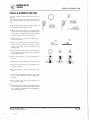
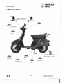
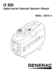
CABLE & HARNESS ROUTING
0
Note the following when routing cables and wire
harnesses.
A loose wire, harness or cable can be a safety hazard.
After clamping, check each wire to be sure it is se·
cure.
•
•
•
•
•
•
•
•
•
•
•
•
Do not squeeze wires against the weld or end of its
clamp when a weld-on clamp is used.
X
Q
Secure wires and wire harnesses to the frame with
their respective wire bands at the designated loca·
tions. Tighten the bands so that only the insulated
surfaces contact the wires or wire harnesses.
Route harnesses so they are not pulled tight or
have excessive slack.
Protect wires and harnesses with electrical tape or
tubing if they are contact a sharp edge or corner.
Clean the attaching surface thoroughly before
applying tape.
Do not use wires or harnesses with a broken insula
tor. Repair by wrapping them with a protective
tape or replace them.
Route wire harnesses to avoid sharp edges or
corners.
Also avoid the projected ends of bolts and screws.
Keep wire harnesses away from the exhaust pipes
and other hot parts.
Be sure grommets are seated in their grooves pro·
perly.
After clamping, check each harness to be certain
that it is not interfering with any moving or slid·
ing parts.
After routing, check that the wire harnesses are
not twisted or kinked.
Wire harnesses routed along the handlebars should
not be pulled tight, have excessive slack, be pinch
ed, or interfere with adjacent or surrounding parts
in all steering positions.
Date of Issue: May, 1983
©HONDA MOTOR CO., LTD.
9
1 -7
� HONDA
� NHSO
GENERAL INFORMATION
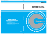
SPEEDOMETER
SPEEDOMETER CABLE
REAR BRAKE CABLE
JUNCTION BOX
MAIN HARNESS
-
REAR BRAKE
CABLE
SPEEDOMETER
CABLE
1 -8
10
Date of Issue: May, 1983
© HONDA MOTOR CO., LTD.
� HONDA
�
NHSO
GENERAL INFORMATION
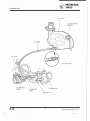
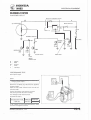
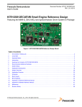
IGNITION SWITCH
THROTTLE/OIL
CONTROL CABLES
THROTTLE CABLE
R ESISTOR
FUEL GAUGE SENSOR
O I L LEVEL
INDICATOR SWITCH
STARTER RELAY
OIL CONTROL
CABLE
IGNITION COIL
TURN SIGNAL
RELAY
REAR BRAKE CABLE
Date of Issue: May, 1983
© HONDA MOTOR CO., LTD.
11
1 -9
� HONDA
�
LUBRICATION
NHSO
OIL TANK
OIL PUMP
O I L STRAINER
CARBURETOR
INTAKE PIPE
2-0
14
Date of Issue: May, 1983
© HONDA MOTOR CO., LTO.
..
HONDA
NH80
2. LUBRICATION
SERVICE INFORMATION
2-1
OIL PUMP BLEEDING
2-3
TROUBLESHOOTING
2-1
OIL PUMP REMOVAL
OIL PUMP CONTROL CABLE
ADJUSTMENT
2-4
2-2
OIL PUMP INSPECTION
FINAL REDUCTION OIL
2-2
2-5
OIL PUMP INSTALLATION
2-2
CONTROL CABLE LUBRICATION
2-5
LUBRICATION POINTS
2-6
SERVICE INFORMATION
GENERAL
The engine must be removed from the frame when removing and installing the oil pump.
• When removing and installing the oil pump, use care not to allow dust and dirt to enter the engine and oil line.
• Bleed air from the oil .pump if there is air in the oil inlet line (from the oil tank to the oil pump) or if the oil line is
disconnected.
• Bleed air from the oil outlet line (from the oil pump to the carburetor) if the line is disconnected.
•
SPECIFICATIONS
Engine oil recommendation:
Final reduction oil capacity:
Final reduction oil recommendation:
Honda 2-stroke oil or equivalent
90 cc (0.09 us qt)
Honda 4-stroke oil or equivalent
Viscosity: SAE 1 OW-40
API Service classification: SE or SF
TORQUE VALUE
Final reduction oil drain bolt
10-14 N-m ( 1 .0-1.4 kg·m, 7-10 ft·lb)
TROUBLESHOOTING
Excessive smoke and/or carbon on spark plug
1 . Pump not properly adjusted (excessive oil)
2. Low quality engine oil
3. Incorrect engine oil
Overheating
1 . Oil pump not adjusted properly (insufficient oiling)
2. Low quality oil
3. Incorrect engine oil
Seized piston
1 . No oil in tank or clogged oil line
2. Pump not properly adjusted (insuffi�ient oiling)
3. Air in oil lines
4. Faulty oil pump
Oil not flowing out of tank
1 . Clogged oil tank cap breather hole
2. Clogged oil strainer
Date of Issue: May, 1983
© HONDA MOTOR CO., LTD.
15
2-1
HONDA
NHSO
LUBRICATION
OIL OUTLET LINE
OIL PUMP
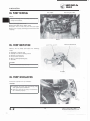
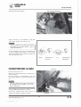
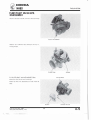
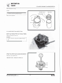
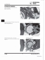
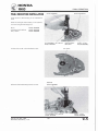
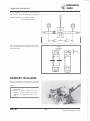
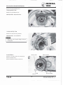
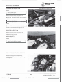
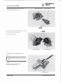
OIL PUMP REMOVAL
NOTE:
Before removing the oil pump, clean the oil
pump and crankcase.
Remove the engine (Section 5).
Remove the starter motor (Page 15·13).
Disconnect the oil outlet line from the intake pipe.
Remove the oil pump attaching bolt and remove the
oil pump.
BOLT
01 L
MATING SUR FACE
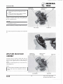
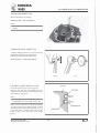
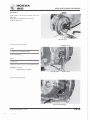
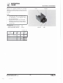
PUMP INSPECTION
Remove the oil pump and inspect the following
items:
• Damaged or weak O·rings
• Damage to crankcase mating surface
• Damage to pump body
• Control lever operation
• Worn or damaged pump gears
• Oil leaks
CAUTION:
Do not disassemble the oil pump.
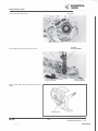
O·RING
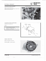
OIL PUMP INSTALLATION
Install the oil pump onto the crankcase.
CAUTION:
• Lubricate the pump gear and O·ring with
clean grease before installation.
•
Make sure that the oil pump is inserted into
the crankcase properly.
2-2
16
Date of Issue: May, 1983
© HONDA MOTOR CO., LTO.
HONDA
NHSO
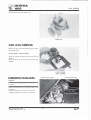
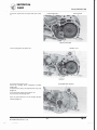
LUBRICATION
OIL OUTLET LINE
Tighten the oil pump attaching bolt securely.
Connect the oil outlet line.
Install the starter motor (Page 15·15).
Install the engine (Page 5-4).
NOTE:
After installation, perform the following inspec·
tions and adjustment:
• Control cable adjustment (Page 2-4)
• Oil pump bleeding.
• Check for oil leaks.
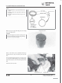
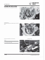
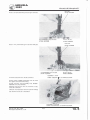
OIL PUMP BLEEDING
CAUTION:
•
Air in the oil system will block or restrict
oil flow and may result in severe engine dam
age.
• Bleed air from the oil inlet line first, then
bleed air from the oil outlet line.
01 L I N LET LI NE/01 L PUMP
CAUTION:
Bleed air from the oil lines whenever the oil
ln
i es or pump have been removed or there is
J
air in the oil lines.
Fill the oil tank with recommended oil.
shop towel around the oil pump.
Disconnect the oil inlet line from the oil pump.
Fill the oil pump with oil by squirting clean oil
through the joint (about 3 cc).
Fill the oil line with oil and connect it to the joint of
the oil pump.
After installation, make sure there is no air in the oil
inlet line.
Place a
CAUTION:
Bleed air from the oil outlet line after bleeding
the oil inlet line and oil pump.
Date of Issue: May, 1983
© HONDA MOTOR CO., LTO.
17
2-3
1
HONDA
NHSO
LUBRICATION
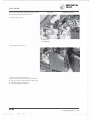
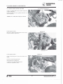
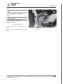
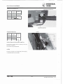
O I L OUTLET LINE
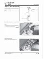
1 . Disconnect the oil outlet line at the carburetor and
force air out of the tube by filling it with oil using
an oil squirt can.
2. Connect the oil outlet line to the carburetor.
3. Start the engine and allow it to idle with the oil
control lever in the fully open position, making
sure that there are no air bubbles in the oil from
the oil pump.
4. If there are air bubbles, repeat steps 1 through 3
until the oil line is free of air bubbles.
• Perform this opemtion in a well vemilated
area.
CAUTION:
• Do not race the engine unnecessarily.
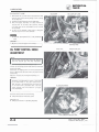
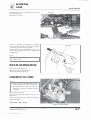
LOCK NUT
OIL PUMP CONTROL CABLE
ADJUSTMENT
ADJUSTING NUT
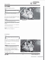
NOTE:
The oil pump control cable should be adjusted
after the throttle grip free play adjustment.
Remove the frame center cover (Page 1 1·3).
Loosen the oil pump control cable lock nut and open
the throttle fully.
Check that the aligning mark on the oil pump control
lever is aligned with the index mark projection on the
pump body.
Adjust if necessary by turning the adjusting nut.
CAUTION:
Reference tip adjustment within 1 mm (0.04
in) of index mark on the open side is accept·
able. However, the aligning mark must never be
on the closed side of the index mark, otherwise
engine damage will occur because of insuffi·
ciem lubrication.
Excessive white smoke or hard starting:
• Pump control lever excessively open
Seized piston:
• Pump control lever not properly adjusted
INDEX MARK PROJECTION
2-4
18
Date of Issue: May, 1983
© HONDA MOTOR CO., LTO.
� HONDA
�
NH80
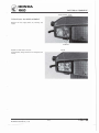
LUBRICATION
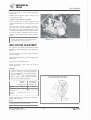
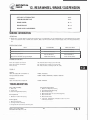
FINAL REDUCTION OIL
CHECK
NOTE:
Place the scooter on a level ground and support
with the center stand.
Remove the oil level check bolt and check that the
oil level is at the oil level check bolt hole.
O I L LEVEL CHECK BOLT HOLE
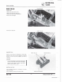
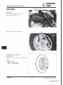
CHANGE
Remove the oil level check bolt.
Remove the drain bolt to allow the oil to drain
thoroughly.
Reinstall the drain bolt.
TORQUE: 10-14 N·m (1.0-1.4 kg-m,
7-10 ft·lb)
NOTE:
Check that the sealing washer is in good condi·
tion.
Fill the final reduction case up to the proper level
with recommended oil.
OIL CAPACITY: 90 cc (0.09 US qt)
SPECIFIED OIL: HONDA 4·STROKE OI L or
equivalent, 10W-40
DRAIN BOLT
CONTROL CABLE LUBRICATION
Periodically disconnect the throttle, oil control and
brake cables at their upper ends. Thoroughly lubri·
cate the cables and their pivot points with a commer·
cially available cable lubricant.
Date of Issue: May, 1 983
© HONDA MOTOR CO., LTD.
19
2-5
� HONDA
� NHSO
MAINTENANCE
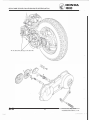
LUBRICATION POINTS
~
[
oc CABLE LUBRICANT I
BRAKE LEVER
P VOTS
THROTTLE AND
BRAKE CABLES
',
'
-�
T HROTTLE GR IP
]
or I CABLE LUBRICANT
SPEEDOMETER CABLE'-............
--
�
--STEERING<--HEAD
'-...,
' ..
- . .....
BEARING
-�
WHEEL
BEARINGS
I
I
I
I
I
1
-�
SPEEDOMETER
DRIVE GEAR
2-6
I
I
I
I
I
-�
FOOT PEG
PIVOT
-�
-�
FINAL R UCTION GEAR
(HONDA 4-STROKE O I L
OR EQUIVALENT, 10W·40)
F I ANAL SHAFT
BEARINGS
CENTER
STAND
PIVOT
20
Date of Issue: May, 1983
© HONDA MOTOR CO., LTO.
HONDA
NH80
3. MAINTENANCE
SERVICE INFORMATION
3-1
COMPRESSION TEST
3-8
MAINTENANCE SCHEDULE
3-2
BATTERY
3-8
FUEL LINES
3-3
BRAKE SHOE WEAR
3-8
FUEL FILTER
3-3
BRAKE SYSTEM
3-9
THROTTLE OPERATION
3-4
PARKING BRAKE
3-10
AIR CLEANER
3-4
BRAKE LIGHT SWITCH
3-10
CARBURETORCHOKE CLEANER
3-5
HEADLIGHT AIM
3-10
SPARK PLUG
3-6
SUSPENSION
3-11
ENGINE OIL LINE
3-6
NUTS,BOLTS,FASTENERS
3-11
ENGINE OIL STRAINER SCREEN
3-6
WHEELS
3-11
MUFFLER DECARBONIZATION
3-7
STEERING HEAD BEARINGS
3-12
CARBURETOR-IDLE SPEED
3-7
SERVICE INFORMATION
GENERAL
Oil pump
Transmission oil
Clutch shoe wear
See page 2-2.
See page 2-4.
See page 8-1 9.
SPECIFICATIONS
<Engine>
Spark plug:
Standard
NGK
BPR6HS
I
I
ND
W20FPR
For extended high speed riding
NGK
ND
W22FPR
BPR7HS
For cold climate (below 5°C, 41 °F)
ND
NGK
BPR5HS
W16FPR
I
I
Spark plug gap:
Throttle grip free play:
Idle speed:
Cylinder compression:
0.6-0.7 mm (0.024-0.028 in)
2-6 mm ( 1 /8-1/4 in)
1,800 ± 100 rpm
10.0-14.0 kg/cm2 (142-200 psi)
<Chassis>
Front brake free play:
Rear brake free play:
1 0-20 mm (3/8-3/4 in)
1 0-20 mm (3/8-3/4 in)
T
T
Tire:
Tire size
Cold tire pressure psi (kPa, kg/cm2)
Date of Issue: May, 1983
©HONDA MOTOR CO., LTD.
I
Up to 90 kg (200 lbsl load
90 kg (200 lbs) load and
up to vehicle capacity load
21
Front
3.50-10-4PR
21 ( 1 50, 1.5)
Rear
3.50-1 0-4PR
24 ( 1 75, 1.75)
21 ( 1 50, 1.5)
36 (250, 2 5)
.
3-1
� HONDA
� NHSO
MAINTENANCE
MAINTENANCE SCHEDULE
Perform the Pre-ride Inspection in the Owner's Manual at each scheduled maintenance period.
INSPECT AND CLEAN, ADJUST, LUBR ICATE, OR REPLACE IF NECESSARY.
I
C
CLEAN
REPLACE
R
A
ADJUST
L
LUBRICATE
��
.
�
WHICHEVER
•
COMES
FI ST
,
7,500 mi Refer to
2,500 mi
5,000 mi
600 mi
( 1 ,000 km) (4,000 km) (8,000 km) ( 12,000 km) page
EVERY
I
F UEL LINES
FUEL FILTER
�
w
THROTTLE OPERATION
1NOTE l
AIR CLEANER
0
w
NOTE 1
CARBURETORCHOKE CLEANER
1�
...J
SPARK
PLUG
w
a:
OIL PUMP
z
0
ENGINE OIL LINES
(/)
(/)
ENGINE O I L STRAINER SCREEN
�
w
MUFFLER DECARBONIZATION
CARBURETOR-IDLE SPEED
TRANSMISSION O I L
2 YEARS R•
(/)
MONTH
BATTE
RY
�
w
BRAKE SHOE WEAR
t:
I- BRAKE SYSTEM
0
w
1I PARKING BRAKE
�
...J
w
BRAKE LIGHT SWITCH
a:
HEADLIGHT AIM
z
0
SUSPENSION
ii5
(/)
NUTS, BOLTS, FASTENERS
�
w
CLUTCH SHOE WEAR
z
0
WHEELS
z
STEERING HEAD BEARINGS
(/)
-
ODOMETER READING (NOTE 2)
I
I
I
R
I
c
c
c
c
R
I
R
I
I
I
•
"
...
I
-
I
I
I
c
c
R
I
I
•
...
.
.
.
.
.
.
..
..
..
--
c
c
I
I
I
I
I
I
I
I
I
I
I
I
I
I
I
I
I
I
I
I
I
I
I
I
I
I
I
I
I
I
I
I
I
I
I
-
I
I
I
I
I
I
I
I
I
3-3
3-3
3-4
3-4
3-5
3-6
2-2
3-6
3-6
3-7
3-7
2-4
3-8
3-8
3-9
3-10
3-10
3-10
3-11
3-1 1
8-19
-
3-11
3·12
* SHOULD BE SERVICED BY AN AUTHORIZED HONDA SCOOTER DEALER, UNLESS THE OWNER HAS PROPER
TOOLS AND SERVICE DATA AND IS MECHANICALLY QUALIFIED.
IN THE INTEREST OF SAFETY, WE RECOMMEND THESE ITEMS BE SERVICED ONLY BY AN AUTHORIZED
HONDA SCOOTER DEALER.
NOTES: 1 . Service more frequently when riding in dusty areas.
2. For higher odometer readings, repeat at the frequency interval established here.
••
3-2
22
Date of Issue: May, 1 983
© HONDA MOTOR CO., LTO.
-
..
HONDA
NHSO
MAINTENANCE
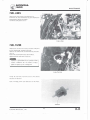
FUEL LINES
Remove the frame center cover (Section 1 1 ) .
Check the fuel lines and replace any parts which show
deterioration, damage or leakage.
Install the frame center cover.
FUEL FILTER
Replace the fuel filter with a new one when indicated
by the maintenance schedule (page 3·2).
Remove the frame center cover and battery box (Sec·
tion 11).
Disconnect the fuel lines from the fuel filter.
Replace the fuel filter with a new one.
Gasoline is flammable and is exp/osil'e under
certain condirions.
Do nor smoke or allow
flames or sparks in your working area.
Install the fuel filter with the arrow in the normal
direction of fuel flow.
After installing, check that there are no fuel leaks.
Date of Issue: May, 1983
©HONDA MOTOR CO.,
LTD.
23
3-3
HONDA
NHSO
MAINTENANCE
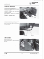
THROlTLE OPERATION
Check for smooth throttle grip full opening and auto·
matic full closing in all steering positions.
Check the throttle cable and replace it, if it is deterio·
rated, kinked or damaged.
Lubricate the throttle cable (page 2·5). if throttle
operation is not smooth.
Measure the throttle grip free play at the throttle
grip flange.
FREE PLAY: 2-6 mm
(1/8-1/4
in)
( 1/a-1/4 i1n)
2-Umm
Adjustments can be made by loosening the lock nut
and turning the throttle grip free play adjuster.
Replace the throttle cable when the above procedure
is no longer effective.
ADJUSTER
AIR CLEANER
A I R CLEANER CASE COVER
LOC NUT
SPRING CLIP
Remove the left frame cover.
Remove the spring clip and remove the air cleaner
case cover.
3-4
24
Date of Issue: May, 1983
© HONDA MOTOR CO., LTD.
HONDA
NH80
MAINTENANCE
Remove the air cleaner element.
A I R CLEANER ELEMENT
Wash the element in non-flammable or high flash
point solvent, squeeze out and allow to dry.
Never use gasoline or low flash point solvents
for cleaning the air cleaner element. A fire or
explosion could result.
Soak the element in clean motor oil (SAE 10W-40)
or gear oil (#80-90) and squeeze out the excess.
Reinstall the element, element holder, air cleaner case
cover and carburetor cover .
WASH
SQUEE ZE OUT
AND DRY
OIL
SQUEEZE OUT
EXCESS OIL
,.
CARBURETORCHOKE CLEANER
ELEMENT
Remove the left frame cover.
Remove the carburetorchoke cleaner chamber and re
move the element.
Wash the element in non-flammable or high flash
point solvent, squeeze out the excess and allow it to
dry.
Never use gasoline or low flash point solvents
for cleaning the cleaner element. A fire or
ex
plosion could result.
Soak the element in clean motor oil (SAE 10W-40)
or gear oil (#80-90) and squeeze out excess.
Reinstall the carburetorchoke cleaner element and
chamber, and clamp the chamber in position.
Date of Issue: May, 1 983
© HONDA MOTOR CO., LTO.
CARBURETORCHOKE CLEANER
CHAMBER
25
3-5
------- -
HONDA
NH80
MAINTENANCE
CENTER ELECTRODE
SPARK PLUG
SIDE ELECTRODE
RECOMMENDED SPARK P L U G
-
Standard
For cold climate
(Below 5°C, 41 °F)
For extended
high speed riding
NGK
NO
BPR6HS
W20FPR
BPR5HS
W16FPR
BPR7HS
l
W22FPR
Disconnect the spark plug cap.
Clean any dirt from around the spark plug base.
Remove and discard the spark plug.
Measure the new spark plug gap using a wire-type
feeler gauge.
SPARK PLUG GAP:
0.6-0.7 mm (0.024-0.028 in)
Adjust by bending the side electrode carefully.
With the plug washer attached, thread the spark plug
in by hand to prevent crossthreading.
Tighten the spark plug another 1/2 turn with a spark
plug wrench to compress the plug washer.
Then connect the spark plug cap.
ENGINE OIL LINE
Remove the frame center cover (Section 1 1 l.
Check the engine oil lines and replace any parts which
show deterioration, damage or leakage.
Bleed the oil pump and oil line, if they have air bub·
bles in them (Page 2·3).
Install the frame center cover.
ENGINE O I L LINES
ENGINE OIL STRAINER SCREEN
Remove the frame center cover (Page 1 1·3).
Disconnect the oil inlet line at the oil pump and allow
the oil to drain into a clean container.
3-6
26
Date of Issue: May, 1 983
© HONDA MOTOR CO., LTO.
.
HONDA
NHSO
MAINTENANCE
Disconnect the oil line at the bottom of the oil tank
by loosening the clip.
Remove the oil strainer.
O I L LINE
CLIP
Clean the oil strainer with compressed air. Replace
the oil strainer if necessary. The installation sequence
is essentially the reverse order of removal.
Fill the tank with the recommended oil up to the
proper level and bleed air from the oil pump and oil
line (Page 2·3).
AIR GUN
NOTE:
•
•
Connect the oil line securely.
Check for leaks.
MUFFLER DECARBONIZATION
Remove the muffler (Page 13·2).
Remove the carbon from the muffler.
Reinstall the muffler (Page 13·3).
CARBURETOR IDLE SPEED
NOT E :
•
•
Inspect and adjust idle speed after all other
engine adjustments are within specifications.
The engine must be warm for accurate ad·
justment. Ten minutes of stop-and-go riding
is sufficient.
Remove the left side cover.
Warm up the engine and place the scooter on its
center stand.
Turn the throttle stop screw as required to obtain the
specified idle speed.
IDLE SPEED:
1,800± 100 rpm
Date of Issue: May, 1983
© HONDA MOTOR CO., LTO.
27
3-7
---- ---- ------ ·
HONDA
NHSO
MAINTENANCE
COMPRESSION TEST
Remove the left frame cover and warm up the engine.
Stop the engine and remove the spark plug.
Insert a compression gauge. Open the throttle grip
fully and operate the kick starter several times.
COMPRESSION: 10.0-14.0 kg/cm2 (142-200 psi)
Low compression can be caused by:
Blown cylinder head gasket
• Worn piston rings
• Worn cylinder
•
High compression can be caused by:
Carbon deposits in combustion chamber or on pis·
ton head
•
COMPRESSION GAUGE
BATTERY
Remove the battery cover.
Inspect the battery fluid level. When the fluid level
nears the lower level mark, refill with distilled water
to the upper level.
• Check the specific gravity of the battery electro·
lyte in each cell (Page 15-3).
• Recharge the battery if necessary (Page 1 5-4).
NOTE:
Add only distilled water. Tap water will shorten
the service life of the battery.
The battery electrolyte contains sulfuric acid.
Protect your eyes, skin and clothing. In case of
LOWER LEVEL
contact, flush thoroughly with water and call a
doctor if electrolyte gets in your eyes.
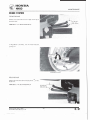
BRAKE SHOE WEAR
Replace the brake shoes if the arrow on the brake
arm aligns with the reference mark "6" when the
brake is fully applied.
3-8
28
Date of Issue: May, 1983
© HONDA MOTOR CO., LTO.
� HONDA
� NHSO
MAINTENANCE
BRAKE SYSTEM
F R O N T BRAKE
10-20 mm
Measure the front brake lever free play at the tip of
the brake lever.
FREE PLAY:
=--r-3--'( /8-3/4 in)
1 0-20 mm (3/8-3/4 in)
If adjustment is necessary, turn the front brake ad·
justing nut.
AOJUST
NG f\UT
REAR BRAKE
Measure the rear brake lever free play a t the tip o f the
brake lever.
FREE PLAY:
10-20 mm (3/8-3/4 in)
Date of Issue: May, 1983
©HONDA MOTOR CO., LTD.
29
3-9
HONDA
NH80
MAINTENANCE
If adjustment is necessary, turn the rear brake adjust
ing nut.
PARKING BRAKE
NOTE:
Parking brake inspection must be made after
the rear brake is adjusted properly.
Apply the parking brake and check that the rear
wheel is locked securely.
Squeeze the rear brake lever. The parking brake
should release automatically.
BRAKE LIGHT SWITCH
Check that the brake light comes on when brake
engagement begins. Replace the switch if the brake
light does not come on at the proper time.
NOTE:
The brake light switches cannot be adjusted.
HEADLIGHT AIM
Adjust the headlight beam vertically by turning the
vertical adjusting screw. Turn the adjusting screw
clockwise to direct the beam down.
VERTICAL ADJUSTING SCREW
-
Adjust the headlight beam horizontally by turning
the horizontal adjusting screw. Turn the adjusting
screw clockwise to direct the beam toward the left
side of the rider.
jA
NOTE:
I
__
_
_
___
_
_
djust the headlight beam as specified by local
laws and regulations.
�
_ _
------
An improperly adjusted headlight may blind
oncoming drivers, or it may fail to light the
road for a safe distance.
3- 1 0
30
Date of Issue: May, 1983
©HONDA MOTOR CO., LTD.
� HONDA
� NHSO
MAINTENANCE
SUSPENSION
Do not ride a scooter with faulty suspension.
Loose, worn or damaged suspension parts
im
pair vehicle stability and control.
FRONT
Check the action of the front fork/shocks by com·
pressing them several times.
Check the entire fork assembly for damage.
Replace damaged components which cannot be re
paired.
Tighten all nuts and bolts.
REAR
Place the scooter on its center stand.
Move the rear wheel sideways with force to see if the
engine hanger bushings are worn.
Replace the hanger bushings if there is any looseness.
Check the shock absorber for damage.
Tighten all rear suspension nuts and bolts.
NUTS, BOLTS, FASTENERS
Check that all chassis nuts and bolts are tightened to
their correct torque values (Section 1) at the intervals
shown in the Maintenance Schedule (Page 3-2).
Check all cotter pins, safety clips, hose clamps and
cable stays.
WHEELS
NOTE:
Tire pressure should be checked when tires are
COLD.
Check the tires for cuts, imbedded nails, or other
sharp objects.
RECOMMENDED TIRES AND PRESSURES:
Tire size
Cold tire
pressure
psi (kPa,
kg/em•)
Front
Rear
3.50-10-4P R
3.50·1 0-4PR
21
Up to 90 kg
1200 lbs) load
(150, 1.5)
24
(175, 1.75)
90
21
(150,1.5)
!250, 2.5)
kg (200 lbs)
and up to vehicle
capacity load
Date of Issue: May, 1983
© HONDA MOTOR CO., LTD.
36
31
3-1 1
------
HONDA
NHSO
MAINTENANCE
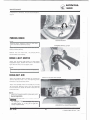
Check the front and rear wheels for trueness.
Measure the tread depth at the center of the tires.
Replace the tires if the tread depth reaches the fol·
lowing limits:
Minimum tread depth:
Front: 0.8 mm (0.03 in)
Rear: 0.8 mm (0.03 in)
-
STEERING HEAD BEARINGS
NOTE:
Check that the control cables do not interfere
with handlebar rotation.
Raise the front wheel off the ground and check that
the handlebar rotates freely.
If the handlebar moves unevenly, binds, or has verti·
cal movement, adjust the steering head bearing by
turning the steering head adjusting nut (Page 1 2·24).
3-1 2
32
Date of Issue: May, 1983
© HONDA MOTOR CO., LTD.
�
------1
F U E L SYSTEM
F U EL TANK
FUEL TUBE
FUEL STRAINER
VACUUM TUBE
4 -0
34
Date of Issue: May, 1983
© HONDA MOTOR CO., LTO.
� HONDA
� NHSO
4. FUEL SYSTEM
SERVICE I N FORMATION
4-1
F LOAT LEVEL I NSPECTION
4-7
TROUBLESHOOTING
4-1
CARBURETOR INSTALLATION
4-7
THROTTLE VALVE DISASSEMBLY
4-2
THROTTLE VALVE
INSTALLATION
4-9
CARBURETOR REMOVAL
4-3
A I R SCREW
4-10
FLOAT/FLOAT VALVE/JETS
DISASSEMBLY
4-5
HIGH ALTITUDE ADJUSTMENT
4-11
JETS/FLOAT VALVE/FLOAT
ASSEMBLY
4-6
R E E D VALVE
4-12
AUTO F U E L VALVE
4-13
SERVICE INFORMATION
GENERAL
Gasoline is extremely flammable and s
i explosive under certain conditions. Work ill a well ventilated area. Do not smoke
or olio w flames or sparks ill the work area.
•
•
•
•
The fuel tank is equipped with an auto fuel valve that is turned OFF automatically when the engine is stopped.
Use caution when working with gasoline. Always work in a well-ventilated area and away from sparks or flames.
When disassembling fuel system parts. note the locations of the 0-rings. Replace them with new ones during assembly.
Bleed air from the oil outlet line whenever it is disconnected.
TOOLS
Special
Hand vacuum pump
Common
FIoat level gauge
ST·AH-260-MC7 ( U.S.A. only)
07401-001 0000
SPE C I F I CATIONS
1 6 mm (0.63 in)
PB54D
8.5 mm (0.335 in)
See page 4-1 0
1,800 ± 100 rpm
2-6 mm ( 1/8-1/4 in)
#88
Venturi dia.
Identification number
Float level
Air screw opening
Idle speed
Throttle grip free play
f-- Main jet
1---
TROUBLESHOOTING
Engine cranks but won't start
1. No fuel in tank
2. Fuel not reaching carburetor
3. Too much fuel getting to cylinder
4. Clogged air cleaner
Rich mixture
1. Faulty float valve
2. Float level too high
3. Carburetor jets clogged
Date of Issue: May, 1983
© HONDA MOTOR CO., LTD.
Engine idles roughly, stalls or runs poorly
1. Idle speed incorrect
2. No spark at plug
3. Loss of compression
4. Rich mixture
5. Lean mixture
6. Clogged air cleaner
7. Intake pipe leaking
8. Fuel contaminated
35
Lean mixture
1. Carburetor fuel jets clogged
2. Fuel cap vent clogged
3. Clogged fuel filter
4. Fuel line kinked or restricted
· 5. Faulty float valve
6. Float level too low
7. Clogged air vent tube
8. Clogged fuel strainer
4-1
Ill
� HONDA
� NHSO
FUEL SYSTEM
CARBURETOR TOP
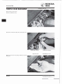
THROTTLE VALVE DISASSEMBLY
Remove the left frame cover.
Remove the carburetor top.
Disconnect the throttle cable from the throttle valve.
TH ROTTLE VALVE
TH ROTTLE CABLE
SEALING CAP
CARBURETOR TOP
Remove the throttle valve spring, carburetor top and
sealing cap.
THROTTLE VALVE SPRING
4-2
36
Date of Issue: May, 1983
© HONDA MOTOR CO., LTO.
� HONDA
� NH80
FUEL SYSTEM
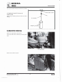
Pry off the needle retainer and remove the jet needle.
�
JET N E E D LE/THROTTLE VALVE
INSPECTION
Check the jet needle and throttle valve for wear or
damage.
NEEDLE RETAINER
CLIP
JET NEEDLE
CARBURETOR REMOVAL
Remove the right and left frame covers.
Loosen the drain screw to drain fuel from the carbu
retor.
DRAIN SCREW
Remove the air cleaner element.
Date of Issue: May, 1 983
©HONDA MOTOR CO., LTD.
37
4-3
HONDA
NHSO
FUEL SYSTEM
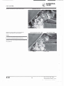
Remove the carburetor top and throttle valve.
CARBURETOR TOP
Disconnect the fuel tube from the carburetor.
Remove the carburetor attaching bolts.
CHOKE CONTROL BOX TUBE
BYSTARTER TUBE
NOTE:
Remove the frame center cover for easy re·
moval of the attaching bolts if necessary.
Disconnect the control box and bystarter tubes from
the carburetor.
BOLTS
FUEL TUBE
-.
4-4
38
Date of Issue: May, 1983
© HONDA MOTOR CO., LTO.
� HONDA
�
NHSO
F U E L SYSTEM
FLOAT/FLOAT VALVE/JETS
DISASSEMBLY
Remove the float chamber from the carburetor body.
FLOAT CHAMBER
Remove the carburetor float and float valve by re
moving the pin.
VALVE SEAT
F LOAT/FLOAT VALVE INSPECTION
Check the valve seat for wear or damage.
Check the float for deformation or fuel inside the
float.
I
FLOAT
Date of Issue: May, 1983
© HONDA MOTOR CO., LTD.
39
/�
FLOAT VALVE
4-5
� HONDA
FUEL SYSTE M
� NH80
NOTE:
• The air screw is factory pre·set and should
not be removed unless the carburetor is over·
hauled.
• The air screw limiter cap is factory installed
to prevent air screw misadjustment.
Remove the throttle stop and air screws. Record the
number of rotations until it seats, so it can be return·
ed to its original positions.
CAUTION:
Do not force the screw against its seat to pre·
vent damage to the seat.
Remove the main jet, needle jet holder and slow jet.
AIR SCREW
SLOW JET
Blow open all jets and body opening with compressed
air.
NEEDLE JET
HO
JETS/FLOAT VALVE/FLOAT
ASSEMBLY
Install the slow jet, needle jet holder and main jet.
Install the throttle stop and air screws and return
them to their original position as noted during re·
moval.
Perform air screw adjustment if a new air screw is in·
stalled (Page 4·1 01.
NOTE:
Do not install a new limiter cap on a new air
screw head until after adjustment has been
made.
4-6
40
Date of Issue: May, 1983
© HONDA MOTOR CO., LTO.
� HONDA
�
NH80
F U E L SYSTEM
Install the float valve, float and float pin.
FLOAT LEVEL INSPECTION
Measure the float level with the float tip just contact·
ing the float valve.
FLOAT LEVEL: 8.5 mm (0.335 in)
Adjust by carefully bending the float arm until the
float tip.
Check operation of the float and install the float
chamber.
CARBURETOR INSTALLATION
CONTROL BOX TUBE
BYSTARTER TUBE
CAUTION:
Do not allow foreign particles to enter the car·
buretor.
Connect the control box and bystarter tubes to the
carburetor.
Install the carburetor and connect the fuel tube.
Install the frame center cover if it was removed.
CARBURETOR
Date of Issue: May, 1983
© HONDA MOTOR CO., LTO.
41
FUEL TUBE
4-7
-------
--------�
HONDA
NHSO
FUEL SYSTEM
Install the throttle valve, aligning the groove in the
throttle valve with the throttle stop screw.
GROOVE
CARBURETOR TOP
Install the carburetor top.
THROTTLE
STOP SCREW
Install the air cleaner element.
Install the right and left frame covers.
Perform the following adjustments and operation:
• Throttle cable free play adjustment (Page 3·4).
• Oil pump adjustment (Page 2·4).
• Idle speed adjust ment (Page 3·7).
4-8
42
Date of Issue: May, 1983
©HONDA MOTOR CO., LTD.
� HONDA
� NHSO
THROTILE VALVE INSTALLATION
FUEL SYSTEM
..-----=
--.
�
Install the jet needle on the throttle valve and secure
with the needle retainer.
Assemble the seal cap, carburetor top and throttle
spring.
NEED L E RETAINER
CLIP
JET NEEDLE
Connect the throttle cable to the throttle valve.
Slide the throttle valve into the carburetor body.
THROTTLE VALVEG RODVE
NOTE:
Align the groove in the valve with the throttle
stop screw on the carburetor body.
THROTTLE STOP SCREW
Tighten the carburetor top.
Install the left frame cover.
Adjust the throttle cable free play (Page 3·4).
Date of Issue: May, 1 983
© HONDA MOTOR CO., lTO.
CARBURETOR TOP
43
4-9
HONDA
NHSO
F U E L SYSTEM
AIR SCREW
REMOVAL/INSTALLATION
NOTE:
The air screw is factory pre-set and should
not be removed unless the carburetor is over
hauled.
Break the tab of the limiter cap with pliers.
Groove the end of the limiter cap with a hacksaw
blade.
Turn the air screw in and carefully count the num
ber of turns so it can be reinstalled in it original
position. Then remove the air screw.
CAUTION:
Damage to air screw and seat can occur if the
air screw is tightened against the seat.
Inspect the air screw and replace it if it is worn or
damaged.
Install the air screw and return it to its original posi
tion as noted during removal.
Perform air screw adjustment if a new screw is in
stalled.
Install a new limiter cap (Page 4-1 1 ) .
ADJUSTMENT
NOTE:
The air screw is factory pre-set and no adjust
ment is necessary unless the air screw is re
placed.
Tvrn the air screw clockwise until it seats lightly
and back it out to the specification given. This is
an initial setting prior to the final air screw adjust
ment.
INITIAL OPENING:
1-1/2 turns out
Damage to the air screw and seat w.ill occur if
CAUTION:
the air screw is tightened against the seat.
Warm the engine up to operating temperature.
Stop and go riding for 1 0 minutes is sufficient.
Connect a tachometer and adjust the idle speed with
the throttle stop screw.
IDLE SPEED: 1,800 ± 100 rpm
4- 1 0
44
Date of Issue: May, 1983
©HONDA MOTOR CO., LTO.
HONDA
NHSO
FUEL SYSTEM
Turn the air screw in or out to obtain the highest
engine speed.
R eadjust the idle speed to 1 ,800 ± 100 rpm, using
the throttle stop screw.
LIMITER CAP I N STALLATION
If the air screw has been removed, a new limiter cap
must be installed after air screw adjust m ent is com·
pleted.
After adjustment, cement the limiter cap over the
air screw, using LOCTITE ® #601 or equivalent.
The limiter cap should be placed against its stop,
preventing further adjustment t hat would enrich the
fuel mixture (limiter cap position permits counter
clockwise rotation and prevents clockwise rotation).
NOTE:
An air screw limiter cap must be installed. It
prevents misadjustment that could cause poor
performance and increase emissions.
LIMITER CAP
HIGH ALTITUDE ADJUSTMENT
For sustained high altitude operation (above 2,000
m/6,500 ftl install a #82 main jet and readjust idle
speed.
Remove the carburetor from the engine and remove
the float chamber.
Replace the standard main jet with the high altitude
#82 main jet.
Assemble and install
Adjust idle speed
the carburetor.
to
1 ,800
throttle stop screw.
CAUTION:
1,500
(5,000
±
100
rpm, using the
Sustained operation at altitudes lower than
m
ft} with the high altitude
main jet installed may cause engine overheating and damage. For sustained operation
below
1,500 m (5,000 ft},
EMISSION CONTROL
INFORMATION UPDATE LABEL
V E H I CLE
reinstall the stand-
ard main jet and readjust idle speed.
Main jet
Idle speed
Air screw
initial
opening
Attach
Update
NOTE:
1
Standard
2,000 m
(6,500 ft ) max.
#88
1 ,800 ± 100 rpm
Factory pre-set
the vehicle Emission
Label as shown.
High altitude
1,500 m
(5,000 ft) min.
#82
type
I
Control Information
Do not attach the label to any part that can
be easily removed from the vehicle.
Date of Issue: May, 1983
© HONDA MOTOR CO., LTO.
45
4-1 1
1
HONDA
NH80
FUE L SYSTEM
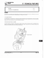
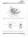
REED VALVE
INTAKE PIPE
REMOVAL
Remove the frame center cover.
Remove the carburetor (Page 4·3).
Remove the engine shrouds (Page 6·2).
Remove the intake pipe.
Remove the reed valve.
REED VALVE
-
INSPECTION
REED VALVE
REED STOPPER
Check the reed valve for damaged or weak reeds.
Check the valve seat for cracks, damage or clearance
between the seat and reed. Replace the valve if
necessary.
l
CAUTION:
Do not disassemble or bend the reed stopper.
To do so can cause loss of power and engine
damage. If the stopper, reed or valve seat is
faulty, replace them as a unit.
INSTALLATION
This installation sequence is essentially the reverse
order of removal.
After installation, check for secondary leaks.
4-1 2
46
Date of Issue: May, 1983
© HONDA MOTOR CO., LTD.
HONDA
NH80
FUEL SYSTEM
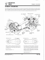
AUTO FUEL VALVE INSPECTION
INSPECTION
Gasoline is extremely flammable and is ex
plosive under certain conditions. Perform this
operation in a well ventilated area and do not
smoke or allow sparks in the area.
__J
_
_
_
_
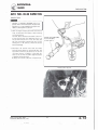
1. With the engine stopped, disconnect the fuel line
from the carburetor and check if fuel is flowing
out of the fuel line.
The fuel valve is normal if fuel ceases to flow out
of the fuel line after the remaining fuel (5-10
cc) has been drained out of the fuel valve and
fuel line thoroughly. Should fuel fail to stop
flowing out of the fuel line, check the vacuum
tube for blockage.
HAND VACUUM PUMP
ST·AH·260·MC7
(U.S.A. ONLY)
2. Disconnect the vacuum tube from the intake
pipe and apply vacuum to the vacuum tube. The
fuel valve is normal if fuel flows out of the fuel
line when vacuum is applied. If fuel does not
flow out of the fuel line when negative pressure
is applied, do the following;
• Clean the vacuum tube with compressed air.
AUTO F U E L VALVE
Date of Issue: May, 1983
© HONDA MOTOR CO., LTO.
47
4- 1 3
� HONDA
� NHSO
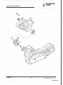
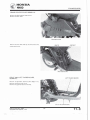
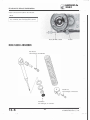
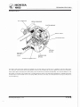
E N G I N E REMOVAL/INSTALLATION
30-40 N·m
{3.0-4.0 kg·m.
22-29 ft·lb)
27-33 N·m {2.7-3.3 kg·m.
20-24 ft·lb)
5-0
48
Date of Issue: May, 1983
© HONDA MOTOR CO LTD.
.•
� HONDA
�
NH80
5 . ENGINE REMOVAL/INSTALLATION
SERVICE I N FORMATION
5-1
ENGINE REMOVAL
5-2
ENGINE INSTALLATION
5-4
SERVICE INFORMATION
GENERAL
Parts requiring engine removal for servicing:
• Oil pump
• Starter motor
• Crankshaft
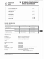
SPEC I F !CATIONS
Engine weight:
1 8 kg (40 lbs)
TORQUE VALUES
Engine mounting bolt
Rear shock absorber upper mounting bolt
Rear shock absorber lower mounting bolt
Date of Issue: May, 1 983
© HONDA MOTOR CO., LTD.
27-33 N·m (2.7-3.3 kg·m, 20-24 ft·lb)
30-40 N·m (3.0-4.0 kg·m, 22-29 ft·lb)
20-30 N·m (2.0-3.0 kg·m, 1 4-22 ft·lb)
49
5-1
� HONDA
� NH80
E N G I N E R E MOVAL/INSTALLATION
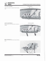
ENGINE REMOVAL
BATTERY GROUND CABLE
Remove the frame center cover.
Remove the right and left floor boards (Section 1 1 ) .
Remove the battery cover and disconnect the bat
tery ground cable from the battery negative termi
nal.
Remove the spark plug cap from the spark plug.
PLUG CAP
Remove the alternator and starter coupler and con
nectors.
5- 2
COUPLER AND CONNECTORS
50
Date of Issue: May, 1 983
© HONDA MOTOR CO., LTD.
� HONDA
� NH80
E N G I N E R E MOVAL/INSTALLATION
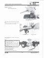
Remove the carburetor top.
Disconnect the vacuum tube and fuel line.
CARBURETOR TOP
VACUUM TUBE
FUEL LINE
Disconnect the rear brake cable.
CABLE CLAMP
Remove the rear shock absorber.
Date of Issue: May, 1983
© HONDA MOTOR CO., LTD.
BRAKE CABLE
CABLE SET PLATE
REAR SHOCK ABSORBER
51
5-3
---..
� HONDA
� NH80
ENGINE REMOVAL/INSTALLATION
Unscrew the nut and remove the engine mounting
bolt.
Slide the engine toward the rear.
ENGINE MOUNTING BOLT
Disconnect the oil control cable.
Disconnect the oil tube.
Remove the engine.
ENGINE INSTALLATION
The installation sequence is essentially the reverse
order of removal.
Tighten the engine mounting bolt and rear shock
absorber upper and lower bolts to the specified
torque values.
O I L TUBE
TORQUE:
Engine mounting bolt: 27-33 N·m
(2.7-3.3 kg-m, 20-24 ft-lb)
Rear shock absorber
upper mounting bolt: 30-40 N·m
(3.0-4.0 kg·m, 22-29 ft-lb)
Rear shock absorber
lower mounting bolt: 20-30 N·m
(2.0-3.0 kg-m,. 1 4-22 ft·lb)
Perform the following inspections and adjustments
after installation:
• Wire and cable routing (Page 1·8, 1-9)
• Throttle cable (Page 3-4)
• Oil control cable (Page 2·4)
• Oil pump bleeding/priming (Page 2-3)
• Rear brake adjustment (Page 3-9)
5-4
52
Date of Issue: May, 1 983
© HONDA MOTOR CO., LTO.
HONDA
NHSO
CYLINDER HEAD/CY LINDER/PISTON
8-12 N·m
(0.8-1.2 kg-m, 6-9 ft-lb)
6 -0
54
Date of Issue: May,
1 983
© HONDA MOTOR CO.,
LTD.
HONDA
NHSO
6. CYLINDER H EAD/CYLINDER/PISTON
SERVICE I N FORMATION
6-1
TROUBLESHOOTING
6-1
CYLINDER HEAD
6-2
CYLINDER/PISTON
6-4
SERVICE INFORMATION
G E N E RAL
•
•
•
•
•
A l l cylinder head, cylinder and piston maintenance and inspection can be done with the engine installed.
Before disassembly, clean the engine to prevent dirt and dust from entering the cylinder and crankcase.
Remove all gasket material from the mating surfaces of the cylinder head, cylinder and crankcase.
Use caution when disassembling and assembling the cylinder head, cylinder and piston to avoid damaging them.
Clean all disassembled parts thoroughly before inspection. Coat all sliding surfaces with clean motor oil before assembly.
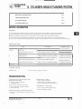
SPECIF ICATIONS
---
ITEM
Warpage
Piston
Piston O.D.
Cylinder-to-piston clearance
-
Piston pin bore
Piston pin O.D.
Piston·to·piston pin clearance
Piston ring end gap (top/second)
r-Connecting rod small end J.D.
Cylinder
STAN DARD
I
Cylinder head
I . D.
47.965-47.975 mm (1 .8884-1.8888 in)
0.035-0.050 mm (0.001 3-0.0020 in)
12.002-12.008 mm (0.4725-0.4728 in)
11 .994-12.000 mm (0.47 22-0.4724 in)
0.002-0.01 2 mm
(0.0001 -0.0005 in)
--0.1 5-0.35 mm (0.006-0.014 in)
17.005-17.017 mm (0.6695-0.6700 in)
I 48.000-48.010 mm (1 .8898-1.8902 in)
SERVICE LIMIT
0.10 mm (0.004 in)
47.900 mm ( 1.8858 in)
0.100 mm (0.0039 in)
1 2.025 mm (0.4734 i n )
1 1 .980 mm (0.4717 in)
0.030 mm (0.0012 in)
0.60 mm (0.024 in)
17.025 m m (0.6703 in)
48.050 mm ( 1 .8917 in)
TORQUE VALUE
Cylinder head
8-12 N ·m
(0.8-1.2 kg·m, 6-9 ft·lb)
TROUBLESHOOTING
Compression too low, hard starting or poor
performance at low speed
1 . Leaking cylinder head gasket
2. Loose spark plug
3. Worn, stuck or broken piston rings
4.
Worn or damaged cylinder and piston
5. Faulty reed valve
Abnormal noise - piston
1. Worn cylinder and piston
2. Worn piston pin or piston pin hole
3. Worn connecting rod small end bearing
Abnormal noise - piston rings
1. Worn, stuck or broken piston rings
2.
Worn or damaged cylinder
Compression too high, overheating or knocking
1 . Excessive carbon build-up in cylinder or on pis
ton top
Date of Issue: May, 1983
© HONDA MOTOR CO., LTD.
55
6-1
� HONDA
� NHSO
CYLINDER HEAD/CY LINDER/PISTON
CYLINDER HEAD
SPARK PLUG CAP
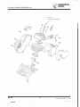
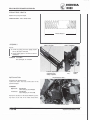
CYLINDER HEAD REMOVAL
Remove the right floor board (Section 1 1 l.
Remove the exhaust muffler (Page 1 3-2).
Remove the cooling fan cover.
Remove the spark plug cap and spark plug.
FAN COVER
Remove the rear shock absorber.
Remove the air cleaner case/rear fender.
SHOCK ABSORBER
A I R CLEANER CASE/REAR F E N D E R
Remove engine shroud A .
6-2
SHROUD A
56
Date of Issue: May, 1 983
© HONDA MOTOR CO., LTD.
� HONDA
� NHSO
CYLINDER HEAD/CYLINDE R/PISTON
Remove the bolts attaching the control box and re
move the control box.
Remove engine shroud B .
SHROUD B
CONTROL BOX
Remove the four cylinder head attaching bolts and
remove the cylinder head.
BOLTS
NOTE:
Loosen the bolts in a criss-cross pattern in
2-3 steps to prevent distorted head.
CYLINDER HEAD
C Y L I N D E R HEAD I NSPECTION
Check the cylinder head for warpage with a straight
edge and a feeler gauge in the directions shown.
SERVICE LIMIT: 0.10
mm (0.004 in)
Date of Issue: May, 1983
© HONDA MOTOR CO., LTD.
57
6-3
HONDA
NHSO
CYLINDER HEAD/CYLINDER/PISTON
DECARBONIZING COMBUSTION
CHAMBER
Remove the carbon build-up from the combustion
chamber using a scraper as shown.
NOTE:
Do not scratch the combustion chamber wall
and cylinder mating surface.
--------�
CYLINDER/PISTON
CYLINDER
C Y L I N D E R REMOVAL
Pull the cylinder up and off being careful not to let
the piston get damaged.
CAUTION:
Do not pry between the cylinder and crank·
case or strike the fins.
------�----�
Place a shop towel into the crankcase around the
piston.
Remove one piston pin clip and press the piston pin
out of the piston.
PISTON
NOTE;
• Do not damage or scratch the piston.
• Do not apply side force to the connecting
rod.
• Do not let the clip fall into the crankcase.
PISTON PIN
6-4
58
CLIP
PISTON PIN
Date of Issue: May, 1983
© HONDA MOTOR CO., LTD.
HONDA
NH80
CYLINDER HEAD/CY LINDER/PISTON
Remove the piston rings.
NOTE:
SECOND R I N G
Spread each piston ring and remove by lifting
it up at a point just opposite the gap.
TOP R I N G
Remove the expander.
CYLINDE R/PISTON INSPECTION
Check the cylinder and piston for wear or damage.
Clean carbon deposits from the cylinder exhaust
port area and piston as shown.
CAUTION:
Do not scratch or score the cylinder and pis
ton
Inspect the cylinder bore for wear at three levels in
and Y directions. Use the largest measurement to
determine the cylinder wear.
X
SERVICE LIMIT: 48.050 mm (1.8917
in)
y
Date of Issue: May, 1 983
©HONDA MOTOR CO.,
LTO.
59
6-5
HONDA
NH80
CYLINDER HEAD/CY LINDER/PISTON
CAUTION:
The cylinder may or may not have an "A "
mark
on
its
crankcase mating surface as
shown. When the cylinder is replaced, replace
it with a similar one, to match the crankcase.
Measure the piston O.D. at a point 4 mm from the
bottom of the skirt.
SERVICE LIMIT: 47.900 mm (1 .8858 in)
Calculate the piston-to-cylinder clearance.
SERVICE LIMIT: 0.100 mm (0.0039 in)
Measure the piston pin
hole 1.0.
PISTON PIN HOLE
1.0.
SERVICE LIMIT: 12.025 mm (0.4734 in)
Measure the piston pin
PISTON PIN 0.0.
O.D.
SERVICE LIMIT: 1 1 .980 mm (0.4717 in)
6-6
60
Date of Issue: May, 1983
MOTOR CO., LTD.
© HONDA
� HONDA
� NHSO
CYLINDER HEAD/CYLINDE R/PISTON
PISTON R I NG INSPECTION
Measure each piston ring end gap.
SERVICE LIMIT:
0.60 mm (0.024 in)
NOTE:
Use the piston to set each ring squarely in the
cylinder.
CONNECTING ROD I NSPECTION
Install the bearing and piston pin in the connecting
rod small end and check for excessive play.
Measure the connecting rod small end I.D.
SERVICE LIMIT:
17.025 mm (0.6703
in)
I.D.
PLAY
PISTON
P I STON/CY L I N D E R INSTALLAT ION
Install the expander in the second ring groove.
Align the ring ends with the locating pins in the
ring grooves and install the top and second rings in
their respective ring grooves.
NOTE:
The top ring is a keystone ring and is not in
terchangeable with the square second ring.
Check the fit of each ring in its groove by pressing
the ring into the groove to make sure that it is flush
with the piston at several points around the ring.
A ring that will not compress means that the ring
groove is dirty or that the ring is in the wrong
groove.
Date of Issue: May, 1983
© HONDA MOTOR CO., LTD.
61
6-7
HONDA
NHSO
CYLINDER HEAD/CY LINDER/PISTON
NOTE:
•
•
•
Install the piston rings with the marks fac
ing up.
Do not replace one ring without replacing
the other.
Do not mix different brands of rings in one
engine.
PISTON R I N G
MARKINGS:
1 T : TDP
2T: SECOND
Make sure that the ring ends align with the locating
pins in the ring grooves.
LOCATI N G PINS
CAUTION:
Be sure the rings do not rotate in their grooves
011er the locating pins to prevent ring breakage
and piston and cylinder damage.
Place a shop towel over the crankcase opening to
prevent piston pin clips from falling into the crank·
case.
Coat the needle bearing and piston pin with 2-stroke
oil. Install the needle bearing in the connecting rod,
and install the piston "EX" mark facing the exhaust
side.
Install new piston pin clips.
6-8
62
Date of Issue: May, 1983
© HONDA MOTOR CO., LTD.
--------�����-- �
� HONDA
� NHSO
CYLINDER HEAD/CY L I N D E R /PISTON
Remove all gasket material from the cylinder and
crankcase mating surfaces.
Place a new cylinder gasket on the crankcase.
Lubricate the cylinder and piston with 2·stroke oil
and install the cylinder over the piston while com
pressing the piston rings.
CAUTION:
A void damaging the sliding swface of the pis
ton.
Date of Issue: May, 1983
© HONDA MOTOR CO., LTD.
63
6-9
HONDA
NHSO
CYLINDER HEAD/CY L I N D E R/PISTON
CYLINDER HEAD BOLTS
CY L I N D E R H E A D I N STALLAT ION
Install the cylinder head on the cylinder using a new
cylinder head gasket.
Install and tighten the four cylinder head bolts in a
criss-cross pattern.
TORQUE:
8-12 N·m (0.8-1.2 kg-m, 6-9ft-lb)
Install engine shroud B.
Clean the cylinder head mating face of the control
box and install the control box.
CDNTRClL BOX
Install engine shroud A.
SHROUD A
Install all removed parts in the reverse order of re
moval.
Perform the following inspections:
Compression test (Page 3-8)
• Check for any abnormal engine noise.
• Check for cylinder air leaks.
•
6- 1 0
64
Date of Issue: May, 1983
© HONDA MOTOR CO., LTD.
� HONDA
� NH80
ALTER NATOR
7-0
66
Date of Issue: May, 1983
© HONDA MOTOR CO., LTO.
� HONDA
� NH80
7. ALTERNATOR
SERVICE I N FORMATION
7-1
ALTER NATOR REMOVAL
7-2
ALTER NATOR INSTALLATION
7-4
SERVICE INFORMATION
GENERAL
• All alternator maintenance can be made with the engine installed
• Do not remove the pulse generator from the stator base.
• See Section 1 5 for alternator inspection.
.
TORQUE VALUE
Flywheel
35-40 N·m (3.5-4.0 kg-m, 25-29 ft·lb)
TOOLS
Common
Rotor puller
Universal holder
Date of Issue: May, 1983
© HONDA MOTOR CO., LTD.
07733-0010000 or 07933-0010000
07725-0030000
67
7-1
l
� HONDA
� NHSO
A LTER NATOR
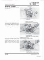
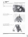
FAN COVER
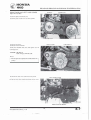
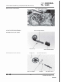
ALTERNATOR REMOVAL
Remove the frame center cover (Section 1 1) .
Remove the muffler.
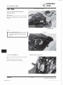
Remove the fan co·1er.
Remove the four bolts attaching the cooling fan and
remove the cooling fan.
Remove the right floor board.
COOLING FAN
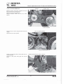
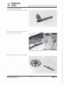
Attach the universal holder to the flywheel.
Hold the flywheel and remove the flywheel 1 0 mm
flange nut.
10 mm FLANGE NUT
7 -2
68
Date of Issue: May, 1983
© HONDA MOTOR CO., LTD.
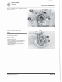
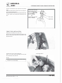
HONDA
NH80
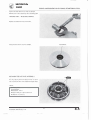
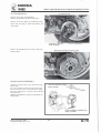
Remove the flywheel with the rotor puller.
Remove the woodruff key.
A LTERNATOR
ROTOR PULLER
07733-0010000 or 07933-0010000
Disconnect the alternator wire connectors.
Remove the two bolts attaching the stator and re·
move the stator.
NOTE:
• Do not remove the pulse generator from
the stator base.
• Avoid damaging the stator coils.
Date of Issue: May, 1983
© HONDA MOTOR CO., LTD.
69
7-3
� HONDA
� NHSO
ALTERNATOR
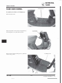
GROMMET
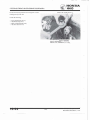
ALTERNATOR INSTALLATION
Install the alternator wire grommet in the case.
Install the stator.
Install the woodruff key in the keyway in the crank·
shaft.
STATOR
Connect the alternator wire connectors.
CONNECTORS
NOTE:
Route the alternator wires properly and se·
cure with the wire clamp.
7-4
70
Date of Issue: May, 1983
© HONDA MOTOR CO., LTD.
..
HONDA
NH80
A LTERNATOR
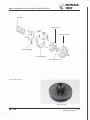
NOTE:
Clean the tapered hole in the flywheel of any
burrs.
Install the flywheel onto the crankshaft.
NOTE:
Make sure that there are no foreign particles
inside the flywheel.
Torque the flywheel 10 mm flange nut.
TORQUE: 35-40 N·m
(3.5-4.0 kg·m, 25-29 ft·lb)
Install all removed parts in the reverse order of re·
moval.
UNIVERSAL HOLDER
07725-0030000
Start the engine and check the ignition timing (Page
15·8).
Date of Issue: May, 1983
© HONDA MOTOR CO., LTD.
71
7-5
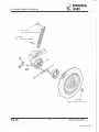
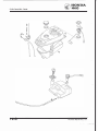
DRIVE AND D R I V E N P U L LEYS/KICK STARTER/CLUTCH
� HONDA
� NH80
35-40 N·m (3.5-4.0 kg·m, 25-29 ft·lb)
8-0
72
Date of Issue: May, 1983
© HONDA MOTOR CO., LTD.
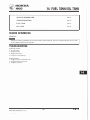
8. DRIVE AND DRIVEN PULLEYS/
KICK STARTER/CLU TCH
HONDA
NHSO
SERVICE I N FORMATION
8-1
TROUBLESHOOTING
8-1
D R I V E PULLEY
8-2
KICK STARTER
8-8
CLUTCH/DRIVEN PULLEY
8-14
SERVICE INFORMATION
GENERAL
•
Avoid getting grease and oil on the drive belt and pulley faces.
SPEC I F !CATIONS
ITEM
Movable drive face bushing I . D.
Drive face boss O.D.
Weight roller O.D.
Clutch outer I.D.
Driven face spring free length
Driven face O.D.
Movable driven face I.D.
STANDARD
24.000-24.021 mm (0.9449-0.9457 in)
23.970-23.990 mm (0.9437-0.9444 in)
17.92-18.08 mm (0.7055-0.71 18 in)
1 1 2.0-112.2 mm (4.41-4.42 in)
64.5 mm (2.54 in)
33.950-33.975 mm ( 1 .3366-1 .3376 in)
34.000-34.025 mm ( 1 .3386-1.3396 in)
SERVICE LIMIT
24.070 mm (0.9476 in)
23.940 mm (0.9425 in)
17.40 mm (0.685 in)
1 1 2.5 mm (4.43 in)
59.1 mm (2.33 in)
33.930 mm (1.3358 in)
34.060 mm ( 1 .3409 in)
TORQUE VALUES
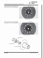
Movable drive face
Movable driven face
Clutch outer
35-40 N·m (3.5-4.0 kg-m, 25-29 ft·lb)
35-40 N·m (3.5-4.0 kg·m, 25-29 tt-lb)
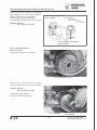
35-40 N·m (3.5-4.0 kg-m, 25-29 ft·lb)
TOOLS
Special
Clutch spring compressor
Bearing driver
Lock nut wrench, 39 mm
Crankcase puller
Bearing driver attachment, 28 x 30 mm
07960-KJ90000
07945-GC80000
07916-1870001
07935-KG80000
07946-1870100
Common
Universal holder
Bearing remover shaft
Bearing remover head, 1 2 mm
Bearing remover head, 1 5 mm
Pilot, 1 5 mm
Driver
07725-0030000
07746-00501 00
07746-0050300
07746-0050400
07746-0040300
07749-0010000
TROUBLESHOOTING
Engine starts but scooter won't move
Worn drive belt
2. Damaged ramp plate
3. Worn or damaged clutch lining
1.
Date of Issue: May, 1983
@ HONDA MOTOR CO., LTD.
Engine stalls or scooter creeps
1. Broken clutch weight spring
73
Poor performance at
1.
2.
3.
4.
high speed or lack of power
Worn drive belt
Weak driven face spring
Worn weight roller
Faulty driven face
8-1
------ -·---
·--
HONDA
NH80
D R I V E A N D D R I V E N P U L LEYS/KICK STARTER/CLUTCH
LEFT CRANKCASE COVER
DRIVE PULLEY
LEFT CRAN KCASE COVER REMOVAL
Remove the frame center cover and left floor board
(Section 1 1 ).
Remove the kick starter pedal.
Remove the bolts and lett case cover.
KICK STARTER PEDAL
DRIVE FACE
D R I V E BELT R E MOVAL
Install the universal holder to hold the flywheel and
remove the 1 0 mm flange nut and drive face.
Remove the drive belt.
Remove the gasket and dowel pins.
CAUTION :
b_
elt_.______
[j?o not bend the drive_
...J
UNIVERSAL HOLDER
077 25-0030000
1 0 mm NUT
·I
D R I VE B E LT
D R I V E BELT I NSPECTION
Check the drive belt for cracks, separation or ab·
normal or excessive wear.
Measure the drive belt width.
SERVICE LIMITS:
13.5 mm (0.531 in)
-
NOTE:
Use a genuine Honda Drive Belt.
I
)b
K ; o {I
- q o&
, 'J
8-2
74
Date of Issue: May, 1 983
© HONDA MOTOR CO., LTO.
HONDA
NHSO
DRIVE AND D R I V E N PULLEYS/KICK STARTER/CLUTCH
MOVABLE DRIVE FACE
MOVABLE DRIVE FACE REMOVAL/
D I SASSEMBLY
Remove the movable drive face assembly.
DRIVE FACE BOSS
Remove the drive face boss.
Remove the three bolts attaching the movable drive
face cover and remove the cover.
FACE COVER
Remove the ramp plate.
Date of Issue: May, 1 983
© HONDA MOTOR CO., LTD.
RAMP PLATE
75
8-3
·---..
HONDA
D R I V E AND D R I V E N PULLEYS/KICK STARTER/CLUTCH
Remove the weight rollers.
NHSO
WEIGHT ROLLERS
-
MOVABLE D R IVE FACE INSPECTION
Check each roller for wear or damage.
Measure each roller O.D.
SERVICE LIMIT:
1 7.40 mm (0.685 in)
Measure movable drive face bushing I.D.
SERVICE LIMIT:
8-4
24.070 mm (0.9476 in)
76
Date of Issue: May, 1983
© HONDA MOTOR CO., LTD.
HONDA
NH80
DRIVE AND DRIVEN PULLEYS/KICK STARTER/CLUTCH
Inspect the drive face boss for wear or damage.
Measure the O.D. at the drive face contacting face.
SERVICE LIMIT:
23.940 mm (0.9425 in)
Replace if smaller than the service limit.
Check the face seal for wear or damage.
FACE SEAL
MOVABLE D R I V E FACE ASSEMBLY
Use 1 0-15g of grease and apply evenly to the in·
side of the drive face. Then install the weight rollers.
NOTE:
Specified grease:
Lithium based
• Mitsubishi: HD-3
• Nippon Sekiyu: Lipanox Deluxe 3
• ldemitsu: Coronex 3
Date of Issue : May, 1 983
© HONDA MOTOR CO., LTD.
77
8-5
--,
HONDA
NH80
DRIVE AND D R I V E N PULLEYS/KICK STARTER/CLUTCH
Install the ramp plate and movable face cover.
Tighten the seal attaching bolts to the specified tor·
que.
TORQUE:
2.5-4.0 N·m
(0.25-0.40 kg·m, 2-3 ft·lb)
- ·� � CG
NOTE:
Make sure that the 0-ring is in position.
\
O·RING
MOVABLE FACE SEAL
RAMP PLATE
Install the drive face boss in the movable drive face.
DRIVE FACE BOSS
MOVABLE D R I V E FACE INSTALLATION
MOVABLE DR IVE FACE
Clean the hole in the movable drive face, drive face
boss and crankshaft.
Install the movable drive face assembly onto the
crankshaft.
CRANKSHAFT
8-6
78
Date of Issue: May, 1 983
© HONDA MOTOR CO., LTO.
� HONDA
� NHSO
D R I V E AND D R I V E N PULLEYS/KICK STARTER/CLUTCH
GASKET
D R I V E FACE A N D LEFT CASE COVER
INSTALLATION
DOWEL PIN
Install the gasket and dowel pins.
Install the plain washer onto the kick spindle.
DOWEL PIN
Install the drive belt.
Install the universal holder.
Install the movable drive face and tighten the 10
mm flange nut.
TORQUE:
35-40 N·m
(3.5-4.0 kg-m,
PLAIN WASHER
DRIVE FACE
DRIVE BELT
25-29 ft·lb)
NOTE:
Do not get oil or grease on the drive belt or
pulleys.
Install the left case cover and kick starter pedal.
LEFT CASE COVER
Install the left floor board and frame center cover.
Date of Issue: May, 1983
© HONDA MOTOR CO., LTD.
79
8-7
DRIVE AND D R I V E N PULLEYS/KICK STARTER/CLUTCH
� HONDA
� NHSO
KICK STARTER
8-8
80
Date of Issue: May, 1 983
© HONDA MOTOR CO.,
LTO.
.,
� HONDA
� NH80
DRIVE AND D R I V E N PULLEYS/KICK STARTER/CLUTCH
KICK STARTER REMOVAL
GASKET
DOWEL PINS
Remove the left case cover, movable drive face
(Page 8·3) and drive belt (Page 8·2).
Remove the gasket and dowel pins.
Remove the plain washer from the kick starter
spindle.
PLAIN WASHER
Remove the kick starter spring from the kick return
stopper.
Remove the kick starter spindle.
KICK STARTER SPRING
KICK STARTER SPINDLE
Attach the crankcase puller as shown with the two
long special bolts.
Remove the kick starter driven gear with the case
puller.
Date of Issue: May, 1983
© HONDA MOTOR CO., LTD.
CRANK CASE PULLER 07935-KG80000
81
8-9
i
I
� HONDA
� NH80
D R I V E AND D R I V E N PULLEYS/KICK STARTER/CLUTCH
Remove the kick starter idle shaft.
KICK STARTER IDLE SHAFT
K I C K STARTER D ISASSE MBLY
KICK STARTER SPINDLE
Disassemble the kick starter spindle.
SPECIAL PIN
Disassemble the kick starter idle shaft.
DOWEL PIN
I
·"
FRICTION SPRING
8- 1 0
82
STARTER IDLE GEAR
/
SPRING
IDLE GEAR SHAFT
Date of Issue: May, 1983
© HONDA MOTOR CO., LTD.
� HONDA
� NH80
DRIVE AND DRIVEN PULLEYS/KICK STARTER/CLUTCH
KICK STARTER INSPECTION
Inspect the kick starter spindle for wear or damage.
Inspect the kick starter spindle bushings and idle
gear shaft bearings for wear or damage.
BUSHINGS
IDLE GEAR SHAFT BEARING
Inspect the idle gear and shaft for wear or damage.
Date of Issue: May, 1983
© HONDA MOTOR CO lTO.
.•
83
8-1 1
� HONDA
� NHSO
DRIVE AND DRIVEN PUL LEYS/KICK STARTER/CLUTCH
KICK STA RTER ASSEMBLY
STARTER IDLE GEAR
DOWEL PIN
Assemble the kick starter idle shaft.
F R I CTION SPRING
SPRING
Install the special pin in the hole of the spindle and
install the spring on the spindle.
ID LE GEAR SHAFT
RETURN SPRING
SPECIAL PIN
KICK STARTER I NSTALLATION
KICK STARTER SPINDLE
CUTOUT
Apply grease to the spring groove and spline of the
idle gear.
Install the kick starter idle gear aligning the dowel
pin on the idle gear with the cutout of the case.
Align the idle gear friction spring with the groove
in the left case as shown.
DOWEL PIN
8-1 2
84
F R ICTION SPRING
Date of Issue: May, 1983
© HONDA MOTOR CO., LTO.
� HONDA
� NH80
D R I V E AND DRIVEN P U L LEYS/KICK STARTER/CLUTCH
Install the starter driven gear.
STARTER DRIVEN GEAR
Install the kick starter spindle; turning the idle gear
to align the punch mark as shown.
Hook the long end of the spindle return spring on
the spring stopper as shown.
Install the drive belt and movable drive face assem·
bly (Page 8·6).
Install the left case cover and kick starter pedal
(Page 8·7).
Install the frame center cover (Section 1 1 ).
SPA I NG STOPPER
RETURN SPR ING
Date of Issue: May, 1983
©HONDA MOTOR CO., LTO.
85
8- 1 3
DRIVE AND D R I V E N PULLEYS/KICK STARTER/CLUTCH
� HONDA
� NHSO
CLUTCH/DRIVEN PULLEY
35-40 N·m
(3.5-4.0 kg·m, 25-29 ft·lb)
8- 1 4
86
Date of Issue: May, 1983
© HONDA MOTOR CO., LTD.
.,
� HONDA
� NHSO
DRIVE AND DRIVEN PULLEYS/KICK STARTER/CLUTCH
CLUTCH REMOVAL
CLUTCH OUTER
Remove the left case cover (Page 8-2).
Remove the movable drive face and drive belt.
Remove the 1 0 mm flange nut holding the clutch
outer with the universal holder and remove the
clutch outer.
UNIVERSAL HOLDER
07725-0030000
1 0 mm FLANGE NUT
Remove the movable driven face and clutch from
the drive shaft.
�
D R I V E N FACE DISASSEMBLY
Position the driven pulley in the clutch spring com·
pressor tool.
Turn the compressor handle to compress the spring.
Be sure the drive bolt is centered on the pulley.
Place the compressor in a vise and remove the 28
mm special nut.
Remove the compressor from the vise and back out
the drive bolt.
LOCK NUT WRENCH, 39mm
07916-1 870001
---..
0
•
CLUTCH SPRING COMPRESSOR
07960-KJ90000
Date of Issue: May, 1983
© HONDA MOTOR CO., LTO.
87
8- 1 5
� HONDA
� NHSO
DRIVE AND DRIVEN PULLEYS/KICK STARTER/CLUTCH
SPRING
DRIVE PLATE
CLUTCH OUTER
CLUTCH SPRING
CLUTCH WEIGHT
28 mm SPECIAL NUT
Remove the seal collar.
SEAL COLLAR
8- 1 6
88
Date of Issue: May, 1 983
© HONDA MOTOR CO., LTD.
� HONDA
� NHSO
DRIVE AND D R I V E N PULLEYS/K ICK STARTER/CLUTCH
Withdraw the guide roller pin and guide roller.
GUIDE ROLLER
GUIDE ROLLER PIN
DRIVEN FACE
MOVABLE DRIVEN FACE
GUIDE RDL
/.r
GUIDE ROLLER
Date of Issue: May, 1983
© HONDA MOTOR CO., LTO.
89
8-1 7
HONDA
NHSO
DRIVE AND DRIVEN PULLEYS/KICK STARTER/CLUTCH
Remove the snap ring and remove the inner bearing
with Bearing Remover Shaft (07746-00501 00) and
Bearing Remover Head, 15 mm (07746-0050400).
SNAP RING
INNER BEAR lNG
Remove the snap ring and remove the outer bearing
with Bearing Remover Shaft (07746-0050100) and
Bearing Remover Head, 12 mm (07746-0050300).
�
SNAP RING
AP R INGS
�Jl{j
�
I
INNER BEARING
I
OUTER BEARING
8- 1 8
90
Date of Issue: May, 1983
© HONDA MOTOR CO., LTO.
HONDA
NH80
DRIVE AND DRIVEN PULLEYS/KICK STARTER/CLUTCH
CLUTCH/ D R I V E N FACE INSPECTION
Inspect the clutch outer for wear or damage.
Measure the clutch outer 1.0.
SERVICE
LIMIT:
112.5 mm (4.43 in)
Inspect the clutch shoes for wear or damage.
Measure the thickness of each shoe.
SERVICE LIMIT: 2.0 mm (0.08 in)
Measure the driven face spring free length.
SERVICE LIMIT: 59.1 mm (2.33 in)
Date of Issue: May, 1983
© HONDA MOTOR CO.,
LTO.
91
8- 1 9
HONDA
D R I V E AND D R I V E N P U L LEYS/KICK STA RTER/CLUTCH
NHSO
Inspect the driven face assembly for wear or dam
age.
Measure the driven face 0.0.
SERVICE
LIMIT: 33.930 mm ( 1.3358 in)
Inspect the movable driven face for wear or damage.
Measure the movable driven face 1.0.
SERVICE
LIMIT: 34.060 mm ( 1.3409 in)
Check the guide groove for wear.
Check the oil seal for wear, damage or other faults.
D R I V E N FACE ASSEMBLY
OUTER BEARING
SNAP RING
Using Bearing Driver (07945-GCSOOOO), install
the outer bearing in the movable driven face with
the sealed end facing out.
Seat the snap ring in its groove.
Pack all bearing cavities with 5.0-5.5 g of grease.
NOTE:
Specified grease: Nippon Sekiyu
LIPANOX DELU X E 3
8-20
92
Date of Issue: May, 1983
© HONDA MOTOR CO., LTO.
� HONDA
� NHSO
DRIVE AND D R I V E N PULLEYS/KICK STARTER/CLUTCH
Using Driver (07749-001 0000) , 28 x 30 mm
Attachment (07946-18701 00, not available in
U.S.A.) and 1 5 mm Pilot (07746-0040300), install
the inner bearing in the movable driven face with
the sealed end facing out.
Install the snap ring.
IN N ER BEARING
Install the movable driven face, guide roller and
roller pin.
Install the seal collar.
SEAL COLLAR
Date of Issue: May, 1983
© HONDA MOTOR CO., LTD.
93
8- 2 1
� HONDA
� NH80
DRIVE AND D R I V E N PULLEYS/KICK STARTER/CLUTCH
Position the driven face assembly, spring and guide
plate assembly on the clutch spring compressor.
Compress the spring by turning the handle.
Install and tighten the 28 mm special nut.
Use a beam type torque wrench 12-14 inches long.
LOCK NUT WRENCH, 39 mm
0791 6-1870001
--
TORQUE: 35-40 N·m
(3.5-4.0 kg·m, 25-29 ft·lb)
CLUTCH SPR ING COMPRESSOR
07960-KJ90000
CLUTCH/ D R I V E N PULLEY
INSTALLATION
Install the driven pulley on the drive shaft.
CLUTCH/DRIVEN PULLEY
Install the clutch outer and torque the nut while
holding the clutch outer with the universal holder.
TORQUE: 35-40 N·m
(3.5-4.0 kg·m, 25-29 ft·lb)
Install the driven face (Page 8·6).
Install the left case cover (Page 8·7).
CLUTCH OUTER
8-22
94
UNIVERSAL HOLDER
077 25-0030000
Date of Issue: May, 1 983
© HONDA MOTOR CO., LTD.
� HONDA
� NHSO
FINAL RED UCTION
9-0
96
Date of Issue: May, 1983
© HONDA MOTOR CO.,
LTO.
HONDA
NH80
9. FINAL REDUCTION
SERVICE I N F O R MATION
9-1
TROUBLESHOOT! N G
9-1
F I N A L R EDUCTION DISASSEMBLY
9-2
FINAL REDUCTION INSPECTION
9-3
F I N A L R EDUCTION INSTALLATION
9-5
SERVICE INFORMATION
GENERAL
Specified oil
Oil quantity
Honda 4-stroke oil
SAE 1 OW-40 or equivalent
90 cc (0.09 us qt)
TOOLS
Special
Bearing remover set, 12 mm
Bearing remover, 15 mm
07936-1660001 (not available in U.S.A.) or 1 07936-1660100
L 07936-3710200
07936-KC10000 (not available in U.S.A.)
Common
Attachment, 32 x 35 mm
Attachment, 37 x 40 mm
Pilot, 12 mm
Pilot, 15 mm
Pilot, 1 7 mm
Driver
07746-0010100
07746-0010200
07746-0040200
07746-0040300
07746-0040400
07749-0010000
TROUBLESHOOTING
Engine starts, but scooter won't move
1. Da:naged transmission
2. Seized or burnt transmission
Abnormal noise
1. Worn, seized or chipped gears
2. Worn bearing
Oil leaks
1. Oi I level too high
2. Worn or damaged oil seal
Date of Issue: May, 1983
© HONDA MOTOR CO., LTD.
97
9-1
� HONDA
� NHSO
FINAL R EDUCTION
FINAL REDUCTION DISASSEMBLY
Remove the driven pulley (Page 8·2).
Drain the oil from the transmission case (Page 2·4).
Remove the rear wheel (Page 13·2).
Remove the transmission case cover bolts and re·
move the transmission cover.
Remove the final gear and countershaft.
FINAL GEAR
COUNTERSHAFT
Remove the drive shaft from the transmission cover.
D R I V E SHAFT
9-2
98
Date of Issue: May, 1983
© HONDA MOTOR CO., LTD.
� HONDA
� NH80
F I N A L R E D UCTION
FINAL REDUCTION INSPECTION
Inspect the drive shaft and gear for wear or damage.
Inspect the countershaft and gear for wear or dam
age.
Inspect the final gear for wear or damage.
Date of Issue: May 1983
© HONDA MOTOR CO., LTO.
,
99
9-3
� HONDA
� NHSO
F I N A L REDUCTION
Inspect the transmission cover bearings, oil seal and
countershaft bore for wear or damage.
If the final gear shaft bearing must be replaced, use
15mm Bearing Remover (07936-KCl 0000, not
available in U.S.A.).
FINAL GEAR SHAFT BEAR lNG
DRIVE SHAFT BEARING
COUNTERSHAFT BORE
Inspect the left crankcase bearings, oil seal and
countershaft bore for wear or damage.
DRIVE SHAFT BEARING
COUNTERSHAFT BORE
Use the bearing remover if drive shaft bearing re·
placement is necessary.
9-4
O I L SEAL
FINAL SHAFT BEARING
OIL SEAL
BEARING REMOVER SET, 12 mm
07936-1660000 (Not available in U.S.A.) or
BEARING REMOVER, 1 2 mm 07936-1660100
and REMOVER WEIGHT 07936-3710200
100
Date of Issue: May, 1983
© HONDA MOTOR CO., LTD.
� HONDA
� NHSO
FINAL REDUCTION INSTALLATION
FINAL R E D UCTION
FINAL GEAR
SHAFT BEARING
DRIVER
07749-0010000
Install the drive shaft bearing in the transmission
cover.
Install the final gear shaft bearing in the transmis
sion cover using the following tools:
Driver
Attachment, 32 x 35 mm
Pilot, 15 mm
07749-0010000
07746-0010100
07746-0040300
ATTACHMENT, 37
07746-0010200
x
40 mm
Install a new oil seal in the transmission cover.
Drive the final shaft bearing into the left case.
'
PI LOT, 1 7 mm
07746-0040400
OIL SEAL
DRIVER
077 49-001 0000
ATTACHMENT, 37
07746-001 0200
Date of Issue: May, 1983
© HONDA MOTOR CO., LTD.
DRIVE SHAFT
BEARING
101
x
40 mm
PILOT, 1 7 mm
077 46-0040400
9-5
HONDA
NH80
FINAL REDUCTION
Install a new final shaft oil seal.
O I L SEAL
D R IVER
07749-0010000
Install the drive shaft bearing into the left case.
ATTACHMENT,
07746-0010100
32 x 35 mm
....
PILOT, 1 2 mm
07746-0040200
Slide the drive shaft through the bearing from the
inside.
D R I V E SHAFT
9-6
102
Date of Issue:
May, 1983
© HONDA MOTOR CO., LTD.
HONDA
NHBO
Install the countershaft, final gear and thrust wash
er.
FINAL REDUCTION
COUNTERSHAFT
FINAL GEAR
THRUST WASHER
Install a new gasket and dowel pins.
DOWEL PINS
Install the transmission cover.
Install the movable driven face/clutch assembly
(Page 8·22).
Install the drive pulley, drive belt and left case cover
(Page 8-7).
Install the frame center cover (Section 11 ) .
Install the rear wheel (Page 1 3-3).
TRANSMISSION COVER
Pour the specified amount of oil through the filler
opening (Page 2-4).
Date of Issue: May, 1983
© HONDA MOTOR CO., LTD.
103
9-7
HONDA
NH80
CRAN KCASE/CRANKSHAFT
1 0-0
104
Date of Issue: May, 1983
© HONDA MOTOR CO., LTD.
HONDA
NHSO
1 0. CRANKCASE/CRANKSHAFT
SERVICE I N FORMATION
10-1
CRANKSHAFT I NSPECTION
10-3
CRAN KCASE SEPARATION
10-2
CRAN KSHAFT I NSTA LLATION
10-4
CRAN KSHAFT R EMOVAL
10-2
CRANKCASE ASSEMBLY
10-6
SERVICE INFORMATION
GENERAL
• This section covers crankcase separation to service the crankshaft.
• The following parts must be removed before separating the crankcase:
Page 5·2
Engine
Page 4-3
Carburetor
Page 2·2
Oil pump
Page 4·12
Reed valve
Page 8·2
Drive pulley
Page 7-2
Alternator
Page 6·2
Cylinder head, cylinder
• In addition to the above, remove the following parts when the left crankcase half must be replaced :
Page 9-2
Final reduction
• When assembling the crankcase and crankshaft, force the crankshaft into the case bore with the special tool rested against
the crankshaft bearing inner race. To do this, it is necessary to remove the old bearing from the crankshaft and drive a new
bearing onto the crankshaft on the case side. Use a new oil seal after assembling the crankcase.
•
SPECIF ICATIONS
ITEM
Connecting rod big end side clearance
Connecting rod big end radial clearance
Crankshaft runout
---
STANDARD
-
I
SERVICE LIMIT
0.5 mm (0.02 in)
0.04 mm (0.0016 in)
0.1 0 mm (0.004 in)
TOOLS
Special
Seal and case assembling tool
Universal bearing puller
Crankcase puller
07965-GC70000 or r- Assembly collar 07965-GC70100
L Assembly tool 07965-1480001
07631-0010000 (not available in U.S.A.)
07935-KG80000
Common
Driver
Attachment, 42 x 47
Pilot, 25 mm
mm
Date of Issue: May, 1 983
© HONDA MOTOR CO., LTO.
07749-0010000
07746-001 0300
07746-0040600
105
1 0- 1
HONDA
NHSO
CRAN KCASE�RANKSHAFT
CRANKCASE SEPARATION
Remove the crankcase attaching bolts.
CRANKCASE PULLER
07935-KG80000
Attach the crankcase puller on the right crankcase
as shown with the two special long bolts.
Separate the right crankcase half.
, __
RIGHT CRANKCASE
CRAN KSHAFT
CRANKSHAFT REMOVAL
Attach the special tool on the left crankcase as
shown with the three special short bolts.
Remove the crankshaft.
CAUTION:
Do not drive the crankshaft out with
a
ham
mer.
PULLER
CRANK
07935-KGSOOOO
1 0- 2
106
Date of Issue: May, 1983
© HONDA MOTOR CO., LTD.
HONDA
NHSO
CRAN KCASE/CRANKSHAFT
Remove the journal bearing from the crankshaft
with the bearing puller.
CRANKSHAFT JOURNAL BEARING
Remove the right and left oil seals.
NOTE:
Replace the oil seals with new ones whenever
disassembled.
UNIVERSAL BEARING PULLER
07631-0010000 (NOT AVAILABLE I N U.S.A.,
EQUIVALENT AVAILABLE IN U.S.A.)
CRANKSHAFT
CRANKSHAFT INSPECTION
Measure the connecting rod big end side clearance
with a feeler gauge.
SERVICE LIMIT:
0.5
mm {0.02 in)
Measure the connecting rod big end radial clearance
at two points in the X and Y directions.
SERVICE LIMIT: 0.04 mm (0.0016 in)
Date of Issue: May, 1983
© HONDA MOTOR CO., LTO.
107
1 0-3
HONDA
NH80
CRAN KCASE/CRANKSHAFT
Set the crankshaft on a stand or in V blocks and
read runout at points A and B using a dial gauge.
SERVICE LIMITS: A: 0.10 mm (0.004 in)
B: 0.10 mm (0.004 in)
J---!iiO mm ---+---!iiO mm
A
(2.4
in)
(2.4 in)
B
Spin the crankshaft bearing by hand and check for
play. The bearing must be replaced if it is noisy or
has excessive play.
AXIAL
CRANKSHAFT INSTALLATION
Wash the crankshaft in solvent and blow dry with
compressed air. Check for cracks or other faults.
NOTE:
• Apply clean engine oil to all moving and
sliding surfaces.
• Remove all gasket materials from the
crankcase mating surfaces. ·Dress any
roughness or irregularities with an oil
stone.
1 0-4
108
Date of Issue: May, 1983
© HONDA MOTOR CO., LTO.
HONDA
NHSO
CRANKCASE/CRANKSHAFT
DRIVER
077 49-001 0000
Drive a new journal bearing into the right crankcase.
... ..,..
... "
PI LOT, 25 mm
07746-0040600
DRIVER
077 49-0010000
Drive a new journal bearing into the left crankcase.
Install the crankshaft into the left crankcase.
PILOT, 25 mm
ATTACHMENT, 42 x 47 mm
07746-0040600
07746-0010300
ASSEMBLY TOOL
07965-1480200 ( NC. IN 07965-GC70000)
Position Collar (07965-GC701 00) with the small
O.D. against the crankshaft bearing.
Thread the bolt from Assembly Tool (079651480200) onto the crankshaft.
Hold the bolt and turn the nut clockwise to fully
install the crankshaft.
lubricate the crankshaft main and journal bearings
with Honda 2-stroke oil or equivalent.
ASSEMBLY COLLAR
07965-GC70100 (INC. IN 07965-GC70000)
Date of Issue: May, 1983
© HONDA MOTOR CO., LTD.
109
1 0- 5
� HONDA
� NH80
CRAN KCASE�RANKSHAFT
CRANKCASE ASSEMBLY
Install a new gasket and dowel pins on the crank·
case mating surface.
DOWEL PINS
ASSEMBLY TOOL COLLAR
07965-GC70100 (INC. IN 07965-GC70000)
Assemble the crankcase halves; place the collar
(07965-GC70100) with the small O.D. against the
right crankshaft bearing. Thread the bolt from as
sembly tool (07965-1480200) onto the crankshaft.
Hold the bolt and turn the nut clockwise to draw
the crankcase halves together.
ASSEMBLING TOOL
07965-1480200 (INC. IN 07965-GC70000)
Install the right oil seal; place the collar (07965GC70100) so its stepped end is against the crank·
case and oil seal.
Thread the bolt from as.sembly tool (079651480200) onto the crankshaft. Hold the bolt and
turn the nut clockwise to install the oil seal into
place.
ASSEMBLING TOOL COLLAR
07965-GC70100 (INC. IN 07965-GC70000)
ASSEMBLY TOOL
07965-1480200 (INC. IN 07965-GC70000)
1 0- 6
110
Date of Issue: May, 1 983
© HONDA MOTOR CO., LTD.
HONDA
NHSO
CRAN KCASE/CRANKSHAFT
Drive the oil seal into the left crankcase until it is
flush with the case.
LEFT 01 L SEAL
Install and tighten the crankcase bolts.
BOLTS
NOTE:
Make sure that the crankshaft rotates freely
after tightening the bolts.
Install the following:
- Final reduction (Page 9·5).
- Alternator (Page 7-4).
Piston, cylinder and cylinder head (Page 6-7).
Drive and driven pulleys (Page 8-6, 8-22).
Oil pump (Page 2-2).
Reed valve and carburetor (Page 4-12, 4-7).
Engine (Page 5-4).
Date of Issue: May, 1983
© HONDA MOTOR CO., LTD.
111
1 0- 7
.
� HONDA
� NH80
FRAME COVERS
1 1 -0
112
Date of Issue: May, 1983
© HONDA MOTOR CO., LTD.
.
� HONDA
� NHSO
1 1 . FRAME COVERS
FRAME COVER REMOVAL
1 1 -2
FRAME COVER INSTALLATION
1 1 -4
Ill
Date of Issue: May, 1983
© HONDA MOTOR CO., LTD.
113
1 1 -1
HONDA
NHSO
FRAME COVERS
FRAME COVER REMOVAL
FLOOR MATS
GLOVEBOX/FLOOR PLATE REMOVAL
Remove the floor mats.
Open the glovebox lid and remove the glovebox by
unscrewing the nut, two bolts and ten screws.
BOLTS
Remove the two bolts attaching the floor plate and
remove the floor plate.
1 1 -2
FLOOR PLATE
I
114
Date of Issue: May, 1983
© HONDA MOTOR CO., LT O .
� HONDA
� NHSO
FRAME COVERS
FRAME CENTER COVER REMOVAL
Remove the right and left frame covers.
Remove the floor mats.
FRAME COVER
Remove the four bolts and cap nut and remove the
frame center cover.
CENTER COVER
R I G H T AND LEFT FLOOR BOARD
REMOVAL
Remove the glovebox and floor plate (Page 1 1 -2).
Remove the frame center cover.
Remove the right and left floor boards.
RIGHT FLOOR BOARD
Date of Issue: May, 1983
© HONDA MOTOR CO., LTO.
115
1 1 -3
1 2. STEERING/FRONT WH EEL/
BRAKE/SUSPENSION
� HONDA
� NH80
SERVICE I N FORMATION
12-1
TROUBLESHOOT! NG
12-2
SPEEDOMETER
1 2-3
HANDLEBAR
1 2-6
FRONT WHEEL
1 2-9
FRONT BRAKE
12-13
FRONT SHOCK
12-16
FRONT FORK
12-20
SERVICE INFORMATION
SPEC I F ICATIONS
ITEM
Axle shaft runout
Rim runout
Cushion spring free length
Front brake drum I.D.
Brake lining thickness
STANDARD
!
I
Radial
Axial
SERVICE LIMIT
0.2 mm {0.01 in)
225.8 mm (8.89 in)
1 1 0.0 mm (4.33 in)
4.0 mm {0.156 in)
2.0 mm (0.08 in)
2.0 mm {0.08 in)
219.0 mm (8.62 in)
1 1 1 .0 mm (4.37 in)
2.0 mm {0.08 in)
--
TORQUE VALUES
Steering stem nut
Front axle nut
Front shock mount bolt
Front fork pivot arm
Front brake arm
80-1 20 N ·m (8.0-12.0 kg-m, 58-87 ft-lb)
50-70 N·m (5.0-7.0 kg·m, 36-51 ft·lb)
30-36 N·m (3.0-3.6 kg·m, 22-26 ft·lb)
20-24 N·m (2.0-2.4 kg·m, 14-17 ft·lb)
8-12 N·m {0.8-1 .2 kg·m, 6-9 ft·lb)
TOOLS
Common
Rear shock absorber compressor
Driver
Attachment, 32 x 35 mm
Attachment, 42 x 47 mm
Pilot, 12 mm
Extension
Lock nut wrench, 30 x 32 mm
Fork seal driver
Fork seal driver attachment
Pin spanner
Date of Issue: May, 1983
© HONDA MOTOR CO., LTD.
07959-3290001
07749-0010000
07746-0010100
077 46-0010300
07746-0040200
07 716 -0020500].
.
.
E qurva Ient too Is commercraIIy avar.1able rn U .S .A.
0771 6_0020400
07747-0010100 ]or Fork seal drrver 07947-3550000
07747_0010400
07702-0020000, 07702-001 0000 or
M9361-41 2-099788 {U.S.A. only)
0
119
1 2- 1
HONDA
NHSO
STEERING/FRONT WHEE L/BRAKE/SUSPENSION
TROUBLESHOOTING
Hard steering
1 . Steering stem nut too tight
2. Steering stem bearings damaged
3. Steering ball and cone races damaged
4. Insufficient tire pressure
Steers to one side or does not track straight
1. Uneven front shocks
2. Bent front fork
3. Bent front axle
Front wheel wobbling
1 . Bent rim
2. Axle nut tightened improperly
3. Bent spoke plate
4. Faulty or unevenly worn tire
5. Excessive wheel bearing play
Soft suspension
1. Weak fork springs
Front suspension noise
1 . Fork link binding
2. Loose front fork fasteners
1 2-2
120
Date of Issue: May, 1983
© HONDA MOTOR CO., LTO.
� HONDA
� NH80
STEERI NG/FRONT WHEE L/BRAKE/SUSPENSION
SPEEDOMETER
METER LOWER COVER
SPEEDOMETER REMOVAL
Remove the meter lower cover by backing off the
one bolt and two screws.
Remove the right and left headlight covers by re
moving the screws.
HEADLIGHT COVERS
Disconnect the front turn signal wires.
Remove the two bolts attaching the handlebar front
cover and remove the front cover with the right and
left front turn signals.
HANDLEBAR FRONT COVER
Date of Issue: May, 1983
© HONDA MOTOR CO., LTD.
121
1 2 -3
HONDA
NHSO
STEER lNG/FRONT W H E E L/BRAKE/SUSPENSION
Disconnect the headlight wires.
Remove the two bolts and headlight.
HEADLIGHT
Remove the windshield by removing the three
screws and two nuts.
WINDSHIELD
\
Disconnect the meter wires and the speedometer
cable.
Remove the rear view mirrors and meter cluster
assembly.
REAR VIEW MIRRORS
SPEEDOMETER
1 2 -4
122
CABLE
Date of Issue: May, 1 983
© HONDA MOTOR CO., LTO.
� HONDA
� NH80
STEERING/FRONT WHEE L/BRAKE/SUSPENSION
BULB SOCKETS
B U L B R E PLACEMENT
Remove the sockets and replace the bulbs with new
ones.
METER D ISASSEMBLY
METER ASSEMBLY
Remove the four screws and remove the meter as·
sembly.
Remove the meter cover.
Remove the indicator panel by releasing the locking
pawls.
LOCKING PAWLS
Date of Issue: May, 1983
© HONDA MOTOR CO., LTD.
123
1 2-5
HONDA
NHSO
STE E R I NG/FRONT WHEEL/BRAKE/SUSPENSION
Remove the meter from the case by removing the
three nuts and two screws.
METER ASSEMBLY/INSTALLATION
The assembly and installation sequence is essentially
the reverse order of disassembly and removal.
HANDLEBAR
R EMOVAL
Remove the meter assembly (Page 12-3).
Remove the left handlebar switch by removing the
two screws.
Remove the right handlebar switch by removing the
two screws.
Disconnect the throttle cable from the throttle grip
and remove the throttle grip from the handlebar.
1 2-6
THROTTLE GRIP
\
124
Date of Issue: May, 1 983
©HONDA MOTOR CO., LTD.
HONDA
NHSO
STEE R I N G/FRONT WHEE L/BRAKE/SUSPENSION
Remove the steering stem cap.
EXTENSION 07716-0020500 OR
COMMERCIALLY AVAILABLE IN U.S.A.
........,_
Remove the steering stem nut.
Remove the handlebar.
LOCK NUT WRENCH, 30 x 32 mm
0771 6-0020400 OR COMMERCIALLY
AVAILABLE IN U.S.A.
I N STALLAT I O N
TABS
Install the handlebar, aligning the tabs of the han·
dlebar bracket with the grooves in the steering stem.
STEM GROOVES
Date of Issue: May, 1983
© HONDA MOTOR CO., LTO.
125
1 2-7
� HONDA
� NHSO
STEERING/FRONT WHEE L/BRAKE/SUSPENSION
EXTENSION 07716-0020500 OR
COMMERCIALLY AVAILABLE I N U.S.A.
Torque the steering stem nut.
TORQUE: 80-120 N·m
(8.0-12.0 kg-m,
58-87 ft-lb)
NCH, 30 x 32 mm
LOCK NUT
07716-0020400 OR COMMERCIALLY
AVAILABLE IN U.S.A.
Apply grease to the throttle grip area of the handle
bar.
Install the throttle grip onto the handlebar and con
nect the throttle cable to the throttle grip.
THROTTLE CABLE
THR
LE GR IP
Install the right and left handlebar switch housings
on the handlebar.
NOTE:
• Align the punch mark on the handlebar
with the split in the housing.
• Tighten the forward screw first, then
tighten the rear screw.
• After tightening the screws, check that the
throttle grip rotates freely in (Ill steering
positions.
Install all the removed parts.
Perform the following adjustments and operations:
• Brake lever free play (Page 3-9)
• Headlight aiming (Page 3-1 0)
• Throttle grip free play (3-4)
• Check the operation of all electrical parts.
1 2 -8
PUNCH MARKS
126
Date of Issue: May, 1983
© HONDA MOTOR CO., LTD.
� HONDA
� NH80
STEERI NG/FRONT W H E E L/BRAKE/SUSPENSION
FRONT WHEEL
CUSHION ARM COVER
REMOVAL
Remove the cushion covers.
Disconnect the speedometer cable from the speedo·
meter gearbox.
Disconnect the brake cable from the brake arm.
Loosen the right and left pivot arm bolts.
Remove the axle nut, withdraw the axle shaft and
remove the front wheel.
BRAKE CABLE
SPEEDOMETER CABLE
INSPECTION
•
AXLE SHAFT
Set the axle in V blocks and measure the runout.
The actual runout is 1/2 of the total indicator read·
ing.
SERVICE
LIMIT: 0.2
mm (0.01 in)
Date of Issue: May, 1983
© HONDA MOTOR CO., LTO.
127
1 2-9
-- �
� HONDA
� NHSO
STEERING/FRONT WHEE L/BRAKE/SUSPENSION
•
WHEEL BEARING
Check the wheel bearing play by placing the wheel
in a truing stand and spinning the wheel by hand.
Replace the bearings if they are noisy or have exces
sive play.
PLAY
AXIAL
•
RADIAL
WHEEL RIM
Check the rim runout by placing the wheel in a
truing stand. Then spin the wheel by hand and read
the runout using a dial gauge.
2.0 mm (0.08 in)
2.0 mm (0.08 in)
SERVICE LIMITS:
Radial:
Axial:
-
DISASSEMBLY
Remove the dust seal, bearings and distance collar-
1 2- 1 0
128
Date of Issue: May, 1983
© HONDA MOTOR CO., LTD.
� HONDA
� NH80
STEERING/FRONT WHEE L/BRAKE/SUSPE NSION
Remove the three flange nuts and remove the spoke
plate from the rim.
FLANGE N UTS
SPOKE PLATE
DRIVER
077 49-001 0000
ASSEMBLY
Install the spoke plate onto the rim and tighten the
flange nut.
TORQUE: 22-28 N·m
(2.2-2.8 kg·m, 16-20 ft·lb)
Pack all bearing cavities with grease.
Drive in the left bearing and install the distance
collar.
Then drive in the right bearing.
NOTE:
• Drive in the bearings squarely.
• Install the bearings with the sealed ends
facing out.
ATTACHMENT, 32 x 35 mm
07746-0010100
•
Contami
nated
'
PI LOT, 12 mm
07746-0040200
brake linings reduce stop
ping power. Keep grease off the linings and
DUST SEAL
brake drum.
Apply grease to the inside of the dust seal.
Install the dust seal and axle collar.
Date of Issue: May, 1983
© HONDA MOTOR CO., LTO.
1 29
COLLAR
��
1 2-1 1
HONDA
NH80
STEERING/FRONT WHEE L/BRAKE/SUSPENSION
STOPPER
INSTALLATION
Position the front wheel between the fork legs.
NOTE:
Align the brake panel groove with the pivot
arm stopper.
Insert the axle shaft through the wheel hub from
the right side and install the axle nut.
Tighten the right and left pivot arm bolts.
TORQUE:
20-24 N·m
(2.0-2.4 kg-m, 14-17
ft-lb)
BRAKE PANEL GROOVE
AXLE SHAFT
Tighten the axle nut to the specified torque.
TORQUE:
50-70 N·m
(5.0-7.0 kg-m, 36-51
AXLE NUT
ft-lb)
Connect the speedometer cable to the speedometer
gearbox.
Connect the brake cable to the front brake arm.
Adjust the front brake lever free play (Page 3-9).
BRAKE CABLE
Install the cushion arm covers with the bolts.
1 2- 1 2
SPEEDOMETER CABLE
CUSHION ARM COVER
130
Date of Issue: May, 1983
© HONDA MOTOR CO., LTO.
� HONDA
� NHSO
STEERING/FRONT WHEE L/BRAKE/SUSPENSION
FRONT BRAKE
8-12 N-m
(0.8-1.2 kg·m,
6-9 ft·lb)
F R O NT BRAKE D R U M INSPECTION
Remove the front wheel (Page
Remove the brake panel.
Measure the brake drum 1.0.
SERVICE LIMIT:
1 2·9).
1 1 1.0 mm (4.37 in)
Date of Issue: May, 1983
© HONDA MOTOR CO., LTD.
131
1 2- 1 3
HONDA
NHBO
STEERI NG/FRONT WHEE L/BRAKE/SUSPENSION
BRAKE L I N I N G INSPECTION
Measure the brake lining thickness.
SERVICE LIMIT:
2.0 mm (0.08 in)
• Contaminated brake linings reduce stop
ping power. Keep grease off the linings.
• Brake dust contains asbestos which can be
harmful to your health. Do not use com
pressed air to clean brake parts. Use a vacu
um with a sealed dust collector. Wear a
protective face mask and wash your hands
wizen finshed.
i
BRAKE PANEL DISASSEMBLY
Remove the brake shoes.
Remove the brake arm and the brake cam.
Remove the speedometer drive gear.
BRAKE P A N E L ASSEMBLY
Lubricate the speedometer drive gear with grease
and install the drive gear in the brake panel.
1 2- 1 4
132
Date of Issue: May, 1983
© HONDA MOTOR CO., LTD.
� HONDA
� NHSO
STEERING/FRONT WHEE L/BRAKE/SUSPENSION
Apply silicone grease to the anchor contacting area
of each shoe and to the brake shoe contacting area
of the brake cam.
Install the brake cam.
BRAKE CAM
Avoid getting grease on the inside of the brake
drum or braking power will be reduced. Qean
the inside of the brake panel thoroughly.
Install the brake shoes.
Install the felt oil seal.
Install the wear indicator plate on the brake cam
shaft.
ALIGN
NOTE:
Align the wide tooth on the plate with the
wide groove on the camshaft.
Install the brake arm.
PUNCH MARKS
NOTE:
Align the punch marks· on the brake arm and
camshaft.
Torque the brake arm bolt.
TORQUE: 8-12 N·m
(0.8-1.2 kg·m, 6-9 ft·lb)
Date of Issue: May, 1983
© HONDA MOTOR CO., LTO.
.
133
1 2- 1 5
·--
� HONDA
� NHSO
STE E R I NG/FRONT WHEE L/BRAKE/SUSPENSION
FRONT SHOCK
FRONT SHOCK REMOVAL
Remove the front wheel (Page 1 2·9).
Remove the pivot arm bolt and the pivot arm.
1 2-1 6
134
Date of Issue: May, 1983
© HONDA MOTOR CO., LTD.
.
�
� HONDA
� NHSO
STEERING/FRONT WHEEL/BRAKE/SUSPENSION
Check the pivot arm bushing A for wear or damage.
If bushing replacement is necessary, remove the
front fork (Page 1 2-20).
PIVOT AR M BUSHING A
Remove the front shock by removing the upper
mount bolts.
UPPER MOUNT BOLT
FRONT SHOCK
FRONT SHOCK D I SASSEMBLY
Place the front shock upper joint in a vise.
Compress the spring by hand and loosen the lock
nut and joint.
Remove the joint and lock nut.
Remove the spring, lower case and spring seat.
LOWER JOINT----�
Date of Issue: May, 1983
© HONDA MOTOR CO., LTD.
135
1 2- 1 7
HONDA
NH80
STEERI NG/FRONT WHEE L/BRAKE/SUSPENSION
Disassemble the shock.
SPRING
�
/ ��
LOWER CASE
LOCK NUT
LOWER
SPRING SEAT
LOWER
JOINT
SPRING I N SPECTION
Measure the spring free length.
SERVICE
LIMIT:
2 1 9.0 mm (8.62
in)
..,_
_
_
_
_
_
--w
FRONT SHOCK ASSEMBLY/
I N STALLATION
Place the front shock upper joint in a vise.
Extend the damper rod fully. Install the upper
spring seat, spring, lower case and lower spring seat.
Apply a thread lock to the lock nut and screw the
lock nut onto the damper shaft completely.
Install the lower joint and tighten the lock nut.
1 2- 1 8
21 9.0 mm (8.62 in) -----�
LOWER JOINT
136
Date of Issue: May, 1983
© HONDA MOTOR CO., LTD.
� HONDA
� NHSO
STEERING/FRONT W H E E L/BRAKE/SUSPENSION
Slide the front shock into the front fork and secure
with the upper mounting bolt.
N·m
(3.0-3.6 kg·m, 22-26 ft-lb)
TORQUE: 30-36
Lubricate and loosely install the front fork pivot
arms with the attaching bolts and nuts.
Install the front wheel (Page 12-12).
FRONT FORK PIVOT ARM
Date of Issue: May, 1983
© HONDA MOTOR CO., LTO.
137
1 2- 1 9
� HONDA
� NHSO
STEERI NG/FRONT WHEEL/BRAKE/SUSPENSION
FRONT FORK
LOCK NUT
F R O NT F O R K REMOVAL
Remove the following:
- Meter assembly (Page 1 2-3).
- Handlebar (Page 12-6).
- Front wheel (Page 12-9).
- Glovebox (Section 1 1 ) .
- Steering stem nut.
PIN SPANNER 07 02-0020000, 07702-0010000
or M9361-41 2-099788 ( U.S.A. only)
1 2 -20
138
Date of Issue: May, 1983
© HONDA MOTOR CO., LTD.
HONDA
NH80
STE E R I NG/FRONT WHEE L/BRAKE/SUSPENSION
Remove the top cone race and remove the front
fork.
TOP CONE RACE
FRONT FORK
NOTE:
Place the steel balls in a parts tray
not lost.
so
they are
FRONT F E N D E R REMOVAL
FRONT FENDER
Remove the two bolts attaching the front fender
and remove the front fender.
Date of Issue: May, 1983
© HONDA MOTOR CO., LTD.
139
1 2-21
� HONDA
� NHSO
STE E R I NG/FRONT W H E E L/BRAKE/SUSPENSION
Drive in a new bottom ball
race
ATTACHMENT, 42 x 47 mm
07746-001 0300
until it bottoms.
NOTE:
Do not allow the ball race to tilt during instal
lation.
DRIVER
07749-001 0000
DRIVER
07749-001 0000
Drive in a new top ball race until it bottoms.
NOTE:
Do not allow the ball race to tilt during instal·
Iation.
BOTTOM CONE RACE REPLACEMENT
Remove the bottom cone race with a cold chisel, be·
ing careful not to damage the steering stem.
1 2-22
140
Date of Issue: May, 1983
© HONDA MOTOR CO., LTD.
•..
. - ---·-- -----
HONDA
NHSO
Install a new bottom cone race over the steering
stem.
Install the old bottom cone race over the new bot
tom cone race upside down.
Drive the bottom cone race with special tools until
it seats in place, then remove the old bottom cone
race.
STEERING/FRONT WHEE L/BRAKE/SUSPENSION
FORK SEAL DRIVER
07747-001 0100 and --"'
""";;:;,q"
FORK SEAL DRIVE R
ATTACHMENT
07747-0010400
OR
F O R K SEAL DRIVER
07947-3550000
OLD RACE
NEW RACE
FRONT FORK I NSTALLATION
Install the front fender on the front fork.
Coat the ball races with grease and install 26 steel
balls on the top ball race and 29 steel balls on the
bottom ball race.
FRONT FORK
Lubricate the top cone race with grease.
Screw in the race until snug against the top ball
race, then back it out 1 /8 turn.
FENDER
TOP CONE RACE
NOTE:
Check that the steering stem rotates freely
and there is no vertical play.
Date of Issue: May, 1983
© HONDA MOTOR CO., LTO.
141
1 2-23
� HONDA
� NHSO
STEERING/FRONT W H E E L/BRAKE/SUSPENSION
Install the head top thread nut and tighten it while
holding the top cone race.
HEAD TOP THREAD NUT
Install the following:
-
Front wheel (Page 12·12)
Handlebar (Page 1 2·7)
Meter assembly (Page 1 2·6)
Glovebox (Section 1 1 )
PIN SPANNER
07702-0010000 or
M9361-41 2-099788 (U.S.A. only)
1 2-24
142
Date of Issue: May, 1983
© HONDA MOTOR CO., LTO.
� HONDA
� NH80
REAR W H E E L/BRAKE/SUSPENSION
30-40 N.m
(3.0- 4.0 kg·m, 22-29 ft·lb)
20-30 N.m
12.0 - 3.0 kg·
�
80-100 N.m
(8.0 - 1 0.0 kg·m, 58-72 ft·lb)
1 3- 0
144
Date of Issue: May, 1983
© HONDA MOTOR CO.,
LTO.
HONDA
NHSO
1 3. REAR WH EEL/BRAKE/SUSPENSION
SERVICE I N FORMATION
13-1
TROUBLESHOOTING
13-1
REAR WHEEL
13-2
REAR BRAKE
13-3
REAR SHOCK ABSORBER
13-6
SERVICE INFORMATION
GENERAL
• Brake dust contains asbestos which can be harmful to your health. Do not use compressed air to clean brake drums or brake
pads. Use a vacuum with a sealed dust collector. Wear a protective face mask and thoroughly wash your hands when finish·
ed.
SPECIFICATIONS
ITEM
Rear wheel rim runout
Brake drum I.D.
Brake lining thickness
Rear shock absorber spring free length
STANDARD
95.0 mm (3.74 in)
5.0 mm (0.20 in)
228.6 mm (9.00 in)
SERVICE LIMIT
2.0 mm (0.08 in)
95.5 mm (3.76 in)
2.0 mm (0.08 in)
221.7 mm (8.73 in)
TORQUE VALUES
Rear shock upper mount bolt
Rear shock lower mount bolt
Rear axle nut
30-40 N·m (3.0-4.0 kg·m, 22-29 ft-lb)
20-30 N·m (2.0-3.0 kg-m, 1 4-22 ft·lb)
80-100 N·m (8.0-10.0 kg-m, 58-72 ft-lb)
TOOLS
Special
Rear shock absorber attachment A
Spring attachment holder
07967-GA70101
07967-07967-GC80000 or 07967-1 180100
Common
Rear shock absorber compressor
07959-3290001
TROUBLESHOOTING
Rear wheel wobbling
1 . Bent rim
2. Faulty tire
3. Axle not tightened properly
Soft suspension
1. Weak shock absorber spring
Brake squeaks
1 . Worn brake linings
2. Foreign matter on linings
3. Rough brake drum shoe contacting face
Date of Issue: May, 1983
© HONDA MOTOR CO., LTD.
Poor brake performance
1. Brake not adjusted properly
2. Contaminated brake linings
3. Worn brake linings
4. Worn brake shoes at cam contacting area
5. Worn brake cam
6. Worn brake drum
7. Improper engagement between brake arm and
camshaft serrations
145
1 3- 1
� HONDA
� NH80
REAR WHEEL/BRAKE/SUSPENSION
REAR WHEEL
EXHAUST MUFFLER
REMOVAL
Remove the frame center cover (Section 1 1 ) .
Remove the exhaust muffler.
Remove the axle nut and the rear wheel.
AXLE NUT
REAR W H E E L R I M RUNOUT
INSPECTION
Check the rim for runout using a dial gauge as
shown.
SERVICE LIMITS:
Radial:
2.0 mm (0.08
Axial:
2.0 mm (0.08
1 3-2
in)
in)
146
Date of Issue: May, 1983
© HONDA MOTOR CO., LTO.
HONDA
NHSO
REAR WHEE L/BRAKE/SUSPENSION
REAR W H E E L SPOKE
FLANGE NUTS
Remove the three flange nuts attaching the spoke
plate to the wheel rim and remove the spoke plate.
Reinstall the spoke plate and tighten the flange nut.
TORQUE:
22-28 N·m
(2.2-2.8 kg-m, 16-20 ft·lb)
SPOKE PLATE
INSTALLATION
AXLE NUT
Install the rear wheel and tighten the axle nut.
TORQUE:
80-100 N·m
(8.0-10.0 kg·m, 58-72 ft-lb)
Install the muffler.
TORQUE:
8 mm bolts: 40-50 N·m
(4.0-5.0 kg-m, 29-36 ft·lb)
Install the frame center cover.
REAR BRAKE
REAR BRAKE CAM
�
�
7
4-7 N·m
{0
'��.P
��
\
0.7
kg·m, 3-5 ft·lbl
"'t>
REAR BRAKE ARM
Date of Issue: May, 1983
© HONDA MOTOR CO., LTD.
147
1 3- 3
� HONDA
� NH80
REAR WHEE L/BRAK E/SUSPENSION
Remove the rear wheel (Page 13-2).
DRUM INSPECTION
Measure the rear brake drum I.D.
SERVICE LIMIT: 95.5 mm (3.76 in)
L I N ING INSPECTION
Measure the rear brake lining thickness.
SERVICE L IMI T: 2.0 mm (0.08
in)
Keep grease off the brake linings.
excess grease.
Wipe
off
D I SASSEMBLY
BRAKE CAM
BRAKE SHOES
Disconnect the brake cable from the brake arm.
Remove the brake shoes.
Remove the brake arm and the brake cam.
BRAKE ARM
1 3 -4
148
BRAKE CABLE
Date of Issue: May, 1 983
© HONDA MOTOR CO., LTD.
� HONDA
� NH80
REAR WHEE L/BRAKE/SUSPENSION
ASSEMBLY
Apply grease to the anchor contacting area of the
brake cam.
Apply grease to the brake cam, and install.
Install the brake shoes.
BRAKE CAM
Install the wear indicator plate.
SCRIBED LINES
NOTE:
Align the wide groove on the cam with the
wide tooth on the indicator plate.
Install the brake arm.
NOTE:
Align the scribed lines on the brake cam and
brake arm.
Tighten the brake arm bolt to the specified torque.
TORQUE: 4-7 N·m
(0.4-0.7 kg·m, 3-5 ft·lb)
BRAKE CAM
BRAKE ARM
Install the brake arm spring.
BRAKE ARM SPRING
Date of Issue: May, 1 983
©HONDA MOTOR CO., LTD.
149
1 3- 5
HONDA
NH80
REAR WHEEL/BRAKE/SUSPENSION
Connect the rear brake cable to the brake arm.
NOTE:
Insert the brake cable into the groove in the
left crankcase and install the plate as shown.
REAR BRAKE CABLE
PLATE
REAR SHOCK ABSORBER
30-40 N·m
(3.0-4.0 kg·m, 22-29 ft·lb)
©
(§
�
(f)
t
�
20-30 N·m
.0 kg·m, 1 4-22 ft·lbl
1 5-25 N·m
( 1 .5-2.5 kg·m, 1 1-18 ft-lb)
1 3-6
150
Date of Issue: May, 1983
© HONDA MOTOR CO., LTO.
HONDA
NH80
REAR WHEE L/BRAKE/SUSPENSION
REMOVAL
Remove the rear shock absorber upper and lower
bolts.
Remove the rear shock absorber.
ABSORBER ATTACHMENT A
07967 -GA701 01
DISASSEMBLY
ATTACHMENT HOLDER
07967-GC80000
Remove the rear shock absorber lower joint by com
pressing it with the compressor.
SHOCK ABSORBER COMPRESSOR
07959-3290001
LOCK
NUT
LOWER
JOINT
REAR SHOCK ABSORBER SPR!NG
REAR DAMPER
It-
WASHER
I
STOPPER RUBBER
LOWER JOINT
SPR ING
@\
�
LOCK NUT
Date of Issue: May, 1983
© HONDA MOTOR CO., LTD.
151
1 3- 7
� HONDA
� NH80
REAR W H E E L/BRAKE/SUSPENSION
S P R I N G F R E E LENGTH
Measure the spring free length.
SERVICE LIMIT: 221.7
mm
{8.73 in)
FREE LENGTH
ABSORBER ATTACH MENT A
07967-GA70101
ASSEMBLY
ATTACHMENT HOLDER
07967-GC80000
NOTE:
• Install the spring with the tightly wound
coil on the upper metal side.
• Apply locking agent to the lock nut before
installation.
TORQUE: 1 5-25 N·m
{1.5-2.5 kg·m, 1 1-18 ft-lb)
SHOCK ABSORBER
COMPRESSOR
07959-3290001
LOCK
NUT
LOWER
JOINT
UPPER MOUNT BOLT
INSTALLATION
Install the rear shock absorber.
Tighten the upper and lower mount bolts to the
specified torques.
TORQUES:
Upper bolt:
Lower bolt:
30-40 N·m
{3.0-4.0 kg-m, 22-29 ft-lb)
20-30 N·m
(2.0-3.0 kg-m, 14-22 ft-lb)
Check the operation of the shock absorber by press
ing down on the end of the frame several times.
LOWER MOUNT BOLT
1 3 -8
152
Date of Issue: May, 1983
© HONDA MOTOR CO., LTO.
� HONDA
� NH80
FUEL TAN K/OI L TANK
1 4-0
154
Date of Issue: May, 1983
© HONDA MOTOR CO., LTD.
� HONDA
� NHSO
1 4. FUEL TANK/OIL TANK
SERVICE I N FORMATION
14-1
TROUBLESHOOTING
14-1
F U E L TANK
14-2
O I L TANK
14-4
SERVICE INFORMATION
GENERAL
Gasoline is extremely flammable and
s
i
explosive under certain conditions. Work in a well ventilated area. Do not smoke
or allow flames or sparks in the work area.
TROUBLESHOOTING
Engine fails to start
1 . No fuel in tank
2. Clogged fuel line
3. Clogged fuel strainer
4. Stuck fuel valve diaphragm
Mixture too lean
1. Clogged fuel tank cap breather hole
2. Clogged or collapsed fuel line
3. Clogged fuel strainer
Date of Issue: May, 1983
© HONDA MOTOR CO LTO.
.•
1 55
1 4- 1
HONDA
NH80
F U E L TANK/O I L TANK
FUEL GAUGE SENSOR
FUEL TANK
F U E L GAUGE SENSOR R E M OVAL/
INSTALLATION
Raise the seat.
Disconnect the fuel gauge sensor wire connectors.
Remove the fuel gauge sensor by turning it counter·
clockwise.
NOTE:
• Do not bend the float arm.
• Install the fuel gauge sensor with the arrow
on the sensor aligned with the arrow on the
fuel tank.
F U E L TANK REMOVAL
A RROWS
R ESISTOR WIR E CONNECTOR
"
Remove the frame center and rear covers (Section
11).
Disconnect the resistor wire connector.
Remove the bolt and take out the battery.
BATTERY BOX
1 4- 2
156
Date of Issue: May, 1983
© HONDA MOTOR CO., LTO.
--- -- ----
� HONDA
� NHSO
F U E L TANK/O I L TANK
Disconnect the fuel and vacuum tubes.
FUEL TUBE
VACUUM TUBE
Remove the seat.
Disconnect the fuel gauge sensor wire connectors.
Remove the fuel tank mount bolts and remove the
fuel tank.
Remove and clean the fuel strainer.
Remove the fuel gauge sensor (Page 14-2).
Check the fuel gauge sensor's operation (page 1518).
F U E L TANK I NSTALLATION
r----- ---------.
The installation sequence is essentially the reverse
order of removal.
Date of Issue: May, 1983
© HONDA MOTOR CO., LTD.
157
1 4-3
� HONDA
� NH80
F U E L TANK/OI L TANK
OIL TANK
OIL TANK
REMOVAL/INSTALLATION
Remove the frame center and rear covers. (Section
11)
Drain oil from the oil tank.
Disconnect the oil level indicator switch coupler.
Remove the oil tank.
Clean the oil strainer (Page 3-6).
To install, reverse the foregoing removal procedure.
Bleed the oil line after installing the oil pump (Page
2·3).
O I L LEVEL IND ICATOR SWITCH COUPLER
1 4-4
158
Date of Issue: May, 1983
© HONDA MOTOR CO., LTO.
� HONDA
� NH80
1 5 . ELECTRICAL EQUIPMENT
SERVICE I N FORMATION
15-1
STARTING SYSTEM
15-11
TROUBLESHOOTING
1 5-2
SWITCHES/HORN
15-15
BATTERY
1 5-3
FUEL GAUGE SENSOR
15-17
CHARGING SYSTEM
15-5
OIL LEVEL I NDICATOR UNIT
15-18
IGNITION SYSTEM
1 5-8
FRONT TURN SIGNALS
15-19
SERVICE INFORMATION
GENERAL
•
•
•
•
•
Do not quick charge the battery. Quick charging may damage the battery.
Remove the battery from the motorcycle for charging. Remove the cell caps before charging the battery.
Do not smoke or have flames near a charging battery. The gas produced by a battery is very flammable and can explode.
Ignition timing cannot be adjusted.
If the timing is incorrect, inspect the COl unit and pulse generator and replace any faulty parts.
SPECIF !CATIONS
CHARGING SYSTEM
Battery
Alternator
ITEM
Capacity
Specific gravity
Charging rate
Charging rpm
Capacity
SPECIFICATIONS
12V SAH
1.270-1.290-at 20° C (68° F)
O.SA max.
2,000 rpm max. 16.4V
0.9A min./4,000 rpm (17.7V)
1.4A max./6,000 rpm (18.0V)
IGNITION SYSTEM
ITEM
SPECIFI CATIONS
Spark plug
Standard
For cold climate
(Below 5° C, 41 ° F)
For extended high
speed riding
Spark plug gap
Ignition coil
resistance
NGK
BPR6HS
NO
W20FPR
BPRSHS
W16FPR
BPR7HS
W22FPR
0.6-0.7 mm (0.024-0.028 in)
Primary
Secondary
0.2-0.3r2
3.4-4.2 kG
14° BTDC at 1,800 rpm
Ignition timing
Date of Issue: May, 1983
© HONDA MOTOR CO., LTO.
159
1 5- 1
---- ·
HONDA
NHSO
ELECTRICAL EQUIPMENT
TROUBLESHOOTING
C H A R G I N G SYSTEM
No power
1. Dead battery
Low fluid level
Battery sulfation
Internally shorted battery
Charging system failure
2. Disconnected battery cable
3. Fuse burned out
4. Faulty ignition switch
Intermittent power
1. Loose battery cable
2. Loose charging system connection
3. Loose connection or short circuit in lighting system
4. Loose ignition system connection
Charging system failure
1. Loose, broken or shorted wire or connection
2. Faulty regulator/rectifier
3. Faulty alternator
Low power
1. Weak battery
2. Loose battery connection
3. Charging system failure
I G N I T I O N SYSTEM
No spark at plug
1 Faulty spark plug
2. Poorly connected, broken or shorted wire
Between pulse generator and CD I unit
Between CDI unit and ignition coil
Between COl unit and ignition switch
Between ignition coil and spark plug
3. Faulty ignition switch
4. Faulty ignition coil
5. Faulty COl unit
6. Faulty pulse generator
.
Engine starts but turns poorly
1. Ignition primary circuit
Faulty ignition coil
- Loose or bare wire or connector
- Poorly contacted ignition switch
2. Ignition secondary circuit
Faulty ignition coil
Faulty spark plug
Faulty high tension wire
Poorly insulated plug cap
3. Improper ignition timing
Faulty pulse generator
Stator not installed properly
Faulty CDI unit
STARTING SYSTEM
Starter won't turn
1 . Fuse burned out
2. Weak battery
3. Faulty ignition switch
4. Faulty starter switch
5. Faulty front or rear stop switch
6. Faulty starter relay
7. Poorly connected, broken or shorted wire
8. Faulty starter motor
1 5- 2
Lack of power
1. Weak battery
2. Loose or bare wire or connection
3. Foreign matter stuck in starter or starter gear
Engine does not crank-starter rotates
1. Faulty starter pinion
2. Low battery
1 60
Date of Issue: May 1983
© HONDA MOTOR CO LTO.
,
.,
� HONDA
� NH80
ELECTRICAL EQUIPMENT
BATTERY
NEGATIVE CABLE
POSITIVE CABLE
R EMOVAL/INSTALLATION
Remove the battery cover.
Remove the battery holder by removing the attach
ing bolt.
Disconnect the negative cable first.
Then disconnect the positive cable.
Remove the battery.
The installation sequence is essentially the reverse
order of removal.
NOTE:
Connect the battery breather tube to the bat
tery br�ather pipe securely.
BATTER Y HOLDER
SPECIFIC G R AVITY TEST
Test each cell by drawing electrolyte into a hydro
meter.
SPECIFIC GRAVITY (20°C, 68° F)
--------,
1 .270-1.290
Fully charged
Undercharged
1.230 or below
HYDROMETER
The battery must be charged if the specific gravity
falls below 1 .230.
ELECTROLYTE
\
-
\
1.31
NOTE:
• The specific gravity varies with the temper
ature as shown. (Specific gravity changes
by 0.007 for every 1 0°C).
• Replace the battery if sulfation has form
ed, or if the space below the cell plates is
filled with sediment.
The battery comains sulfuric acid. Avoid
comact with skin, eyes, or clothing. A ntidote:
Flush with water and get prompt medical
attention.
1.304
t
>f-
><(
�
(.)
u
w
g,
u.
1.27
1.26
1.256
1.25
1.24
ELECTROLYTE TEMP. VS. SPECIFIC GRAVITY
o•
Date of Issue: May, 1983
© HONDA MOTOR CO., LTO.
161
S'
10"
1 S'
20"
25'
30"
35"
40"
ELECTROLYTE TEMPERATURE °C
1 5-3
HONDA
NH80
ELECTRICAL EQUIPMENT
BATTERY C H A R G I N G
Remove the battery.
Remove the cell cap from the battery.
Connect the charger positive (+) cable to the battery
positive (+) terminal.
Connect the charger negative (-) cable to the bat·
tery negative (-) terminal.
Charging current:
•
•
0.5 amperes maximum
Keep flames and sparks away from a charg
ing battery to prevent igniting the hydro·
gen gas produced by the batrery.
Tum power ON/OFF at the charger, not
at the battery terminals to prevent sparks
•
near the battery cells.
charging if the electrolyte
°
temperature exceeds 45 C (11 1'F).
Discontinue
CAUTION:
Quick charging should only be done in an
emergency, slow charging is preferred.
Charging time:
3-15 hours
Charging:
Charge the battery at 0.5A until specific gravity is
1.270-1.290 {20°C, 68° F ) .
>
t:
>
<(
CI:
(.!)
u
u..
u
1.300
1 .280
1.260
1.220
1 . 1 80
UJ
a.
(/)
1
{ 1 ) SPECIFIC GRAVITY VS CHARGING T I M E
(20°C)
1 . 1 40
1 . 1 00
1 60
�
2:�
- !4 �
s:--:!:s �
,-=-o --:
:'::
, 2�
�
·0 0
�
1�
4 16
CHARGING TIME
CAUTION:
Check routing of the breather tube as shown
on the battery caution label.
\
CAUTION
I N SERT T H E B A T T E R Y
T U B E S E C U RE L Y .
1 5-4
162
Date of Issue: May, 1983
© HONDA MOTOR CO LTD.
.•
� HONDA
� NH80
ELECTRICAL EQUIPMENT
CHARGING SYSTEM
CHARGING C I R C U I T
REGULATOR/R ECTI F I E R
r:--------,
w
ALTERNATOR
-,!---+--1
.......---:.:..
-
R
MAIN SWITCH
I
I
L
y
__
DIMMER SWITCH
HI
��------�
HEAD LIGHT
W
R
BL
P
Y
FUSE
�
TAIL
LIGHT
BATTERY
RESISTOR
HIGH
BEAM
IN DICATOR
WHITE
RED
BLACK
PINK
YELLOW
P E R F O R MANCE TEST
Warm up the engine.
NOTE:
Use a fully charged battery to check the
charging system output.
Disconnect the black wire lead from the regulator/
rectifier coupler.
Open the fuse holder and disconnect the red wire
from the holder.
Connect an ammeter and voltmeter as shown.
Start the engine and take meter readings.
The readings should match the chart.
TECHNICAL DATA
Charging rpm ( I nitial)
2,000 max.
4,000 rpm
6,000 rpm
0.9A min.
1 .4A max.
If the readings are not within specifications, check
the stator and regulator/rectifier.
Date of Issue: May, 1 983
© HONDA MOTOR CO., LTD.
163
1 5- 5
HONDA
NH80
ELECTRICAL EQUIPMENT
ALTERNATOR I NSPECTION
STATOR W I R E CONNECTORS
NOTE:
This test can be made without removing the
stator from the engine.
Remove the frame center cover (Section 1 1 ) .
Disconnect the stator wire ooupler.
Measure the resistances between the terminals as
follows:
0.1-1.0 n
0.2-2.0 n
Yellow and engine ground
White and engine ground
NOTE:
Measure the resistances in the
x
1
n range.
Alternator removal/instal l ation (Page 7-2, 7-4).
RESISTOR I N SPECTION
R ES I STOR
Remove the frame center cover (Section 1 1 ) .
Measure the resistance between the resistor wire
lead and any body ground.
RESISTANCE: 6.7 .Q
NOTE:
A faulty or poorly grounded resistor can be a
frequent cause of a blown headlight.
R E G U LATOR/RECT I F I E R INSPECTION
R E GULATOR/A ECTIF l E A
Remove the frame center cover (Section 1 1 ) .
Disconnect the regulator/rectifier coupler.
Remove the regulator/rectifier by removing the
attaching bolt.
COUPLER
1 5- 6
164
Date of Issue: May, 1983
© HONDA MOTOR CO., LTD.
HONDA
NHSO
ELECTRICAL EQUIPMENT
Measure the resistances between the terminals.
Replace the regulator/rectifier with a new one if
the readings do not fall within the limits shown in
the table.
PINK
WHITE
NOTE:
• For accurate testing, it is necessary to use
a specified tester. Use of an improper tester
or measurements in the improper range
may give false readings.
• Use Sanwa Electric Tester SP-10D (073080020000), Kowa Electric Tester TH-5H or
Kowa Digital Multi Tester KS-AHM-32-003
(U.S.A. only).
Measuring range:
SANWA ELECTRIC TESTER:
KOWA ELECTRIC TESTER:
x Kn
x 100 n
BLACK
RED
( 1 1 UNIT: Kn
+
PROBE
- PROBE
PINK
WHITE
BLACK
RED
""'
�
PINK
WHITE
BLACK
RED
�
1-5
00
� ..
.. � ..
00
.. �
0.5-10
1-5
Date of Issue: May, 1983
© HONDA MOTOR CO., LTO.
165
1 5- 7
� HONDA
� NH80
ELECTRICAL EQUIPMENT
IGNITION SYSTEM
IGNITION SYSTEM C I R C U I T
B LACK
YE LLOW
W
WHITE
BLUE
GREEN
RED
ON
ALTERNATOR
IGNITION COIL
I
I
\
BL
Y
BU
G
R
(.!)
:.::>
...J
c..
�
cc
<(
c..
f/)
BU!Y
I
PULSE COIL
G
_ _
_j
SPARK PLUG
For spark plug gap inspection and adjustment, see
Page 3-6.
INDEX MARK
I G N I T I O N T I M I NG
NOTE:
The COl ignition timing is not adjustable. If
the ignition timing is not correct, check the
CDI unit and alternator and replace any faulty
parts.
Remove the fan cover and check the ignition timing
with a timing light.
Timing is correct if the index mark aligns with the
"F" mark (within 3°) at 1,800 rpm.
IGNITION TIMING: 14 ± 3° BTDC at 1,800 rpm
"F" MARK
1 5-8
166
Date of Issue: May, 1983
© HONDA MOTOR CO., LTO.
� HONDA
� NHSO
E LECTRICAL EQUIPMENT
I G N ITION COIL INSPECTION
IGNITION COIL
Remove the left frame cover.
Disconnect the plug cap from the high tension wire
while rotating the plug cap.
Measure the resistances of the primary and second
ary coils.
RESISTANCES:
Primary coil
Secondary coil
o.2-0.3 n
3.4-4.2 kU
PULSE G E N ERATOR INSPECTION
PULSE GENERATOR CONNECTORS
NOTE:
It is not necessary to remove the stator to
make this test.
Rem�ve the frame center cover (Section 1 1 ) .
Disconnect the stator coupler.
Measure the resistances between the terminals with
an ohmmeter.
Black/red- Engine ground
Blue/yellow - Body ground
S0-3oo n
10-100 n
NOTE:
Measure the resistances in the X
1 n range.
Alternator removal/installation (Page 7-2, 7-4).
Date of Issue: May, 1983
© HONDA MOTOR CO., LTO.
167
1 5-9
HONDA
NHSO
ELECTRICAL EQUIPMENT
COl UNIT
CDI U N I T INSPECTION
Remove the left frame cover (Section 1 1).
Disconnect the COl coupler and remove the COl
unit.
Measure the resistances between the terminals.
Replace the COl unit if the readings do not fall
within the limits in the table.
NOTE:
• For accurate testing, it is necessary to use
a specified tester. Use of an improper tester
or measurements in an improper range may
give false readings.
• Use Sanwa Electric Tester SP-100 (073080020000) . Kowa Electric Tester TH-5H or
Kowa Digital Multi Tester KS-AHM-32-003
(U.S.A. only).
• In the table, "Needle swings then returns"
indicates that there is a charging current
applied to a condenser. The needle will
then remain at "
" unless the condenser
is discharged.
oo
PC
E
sw
NOTE:
• Use the x Kn range for Sanwa Tester.
• Use the x 1 00 n for Kowa Tester.
UNIT: Kn
@ .P ROBE
8 PROBE
sw
�
SI'J
�
EXT
PC
E
IGN
00
00
00
00
00
00
PC
0.5-200
�
E
0.2-30
0.1-10
-------
00
00
00
EXT
IGN
1 5- 1 0
0.1-10
0.5-50
00
168
"Needle swings
then returns"
1-50
-----00
00
00
------
Date of Issue: May, 1983
© HONDA MOTOR CO., LTO.
� HONDA
� NHSO
STARTING SYSTEM
ELECTRICAL EQUIPMENT
STARTER SWITCH
IGNITION SWITCH
STARTING CIRCUIT
-
.1.
A /IN
FRONT
STOP
SWITCH
REAR STOP
SWITCH
G!Y
R
Y
W
G
:
:
:
:
RED
YELLOW
WHITE
GREEN
STARTER RELAY
STARTER R E LAY I N SPECTION
STARTER RELAY
The primary coil is normal it you hear a click when
the starter button is depressed.
Connect a 12V battery to the primary coil.
Check for continuity of the secondary terminals.
Replace the starter relay switch with a new one if
there is no continuity.
STARTER R E LAY REMOVAL
Remove the frame center cover (Section 1 1) .
Remove the battery box (Page 15-4).
Remove the starter relay switch.
Date of Issue: May, 1983
© HONDA MOTOR CO., LTO.
169
1 5- 1 1
� HONDA
� NHSO
ELECTRICAL EQUIPMENT
STARTER MOTOR REMOVAL
STARTER MOTOR
Remove the engine (Section 5).
Remove the two bolts attaching the starter motor
and remove the starter motor.
STARTER MOTOR D I SASSEMBLY
Disconnect the starter wires.
NOTE:
• The brush springs will pop out when re
moving the brush holder plate.
• Record the number and location of the
commutator thrust washers.
ROTOR
BRUSH INSPECTION
Measure the length of each brush.
SERVICE LIMIT:
1 5- 1 2
3.0 mm (0.12
in)
170
Date of Issue: May, 1983
© HONDA MOTOR CO., LTD.
� HONDA
� NHSO
ELECTRICAL EQUIPMENT
COMMUTATOR INSPECTION
Check the commutator for discoloration and other
visual faults. Blackened adjacent segments are an
indication of a shorted circuit.
NOTE:
Do not use sand paper to clean the commuta·
tor.
Q
Check for continuity between segments, and com
mutator and shaft. The commutator is normal if
there is continuitY between the segments. There
should be no continuity between the commutator
and shaft.
BRUSH HOLDER
STARTER MOTOR ASSEMBLY
COMMUTATOR
Install the brush springs and brushes in the holder
plate.
Install the commutator and thrust washers while
extending the brushes outward.
NOTE:
Note the number and location of the thrust
washers.
CAUTION :
Check that there is no foreign material inside
the starter body.
Install the commutator with the brush holder into
the starter body.
Date of Issue: May, 1983
© HONDA MOTOR CO. LTO.
.
171
1 5- 1 3
HONDA
NHSO
ELECTRICAL EQUIPMENT
lubricate the starter pinion with clean grease.
Install the pinion and starter cover.
STARTER COVER
PINION GEAR
lubricate the gear on the starter body and install
the starter motor cover on the body.
Connect the starter wires.
STARTER BODY
STARTER COVER
STARTER MOTOR INSTALLATION
NOTE:
Before installing the starter, test for operation
by connecting the starter coupler to the wire
harness.
Install the starter motor in the reverse order of re
moval.
Secure the wires with the wire clamps.
Install the engine (Section 5).
·
STARTER WIRES
1 5- 1 4
172
Date of Issue: May, 1983
© HONDA MOTOR CO., lTO.
r::iJ\ HONDA
�
NH80
ELECTRICAL EQUIPMENT
SWITCHES/HORN
IGNITION SWITCH
Remove the handlebar lower cover and glovebox.
Check the continuity of each switch.
Continuity should exist between color coded wires
indicated by interconnected circles on each chart.
I G N I T I O N SWITCH
COLOR
CODE
ON
OFF
LOCK
RED
BLACK
BAT 1
BAT2
,....
'""
,....
'""
BLACK/
WHITE GREEN
IG
E
0
-Q
T U R N SIGNAL SWITCH
COLOR
CODE
R
N
L
GRAY
0
w
HEADLIGHT HI·LOW SWITCH
LIGHT
BLUE ORANGE
R
L
-o
0
"
�
HORN SWITCH
COLOR
CODE
FREE
PUSH
LIGHT
BLUE
HO
0
BLACK
BAT2
TURN SIGNAL SWITCH
-o
HORN SWITCH
HEADLIGHT H I - LOW SWITCH
COLOR
BROWN
CODE
Hi
0
Lo
0
HL
(N)
()
BLUE
WHITE
Hi
Lo
.()
,..._
Date of Issue: May, 1983
© HONDA MOTOR CO., LTD.
,..._
,..,
-
173
1 5- 1 5
� HONDA
� NH80
ELECTRICAL EQUIPMENT
E N G I N E STOP SWITCH
COLOR
CODE
BLACK/
WHITE
IG
OFF
RUN
OFF
ENGINE STOP SWITCH
GREEN
0
{)
'"'
�
""
�
E
STARTER SWITCH
COLOR
CODE
HORN
YELLOW/
GREEN
RED
ST
F REE
PUSH
0
E
"9
...L
FRONT/REAR STOPLIGHT SWITCH
The switch is normal if there is continuity when the
brake lever is applied.
The switches are not adjustable.
HORN
The horn is normal if it sounds when a 12V battery
is connected across the terminals.
1 5- 1 6
174
Date of Issue: May, 1983
© HONDA MOTOR CO., LTD.
-··- ---------""""'!
� HONDA
� NH80
ELECTRICAL EQUIPMENT
FUEL GAUGE SENSOR
UPPER LIMIT
F U E L G A U G E SENSOR INSPECTION
Remove the sensor from the fuel tank (Page 14·2).
Measure the resistances between the terminals with
the float at the UPPER (FULL) and LOWER
(EMPTY) positions.
Float position
UPPER (FULL)
LOWER (EMPTY)
Resistance
4-lo n
97.5-107.5 n
LOWER LIMIT
F U E L GAUGE INSPECTION
Connect the wire connectors and turn the ignition
switch ON.
NOTE:
Before performing the following test, operate
the turn signals to determine that the battery
circuit is normal.
Check the gauge needle for correct indication by
moving the float up and down.
Float position
FLOAT AT UPPER LIMIT
FLOAT AT LOWER LIMIT
Date of Issue: May, 1983
© HONDA MOTOR CO., LTO.
Needle Position
F ( F U LL)
E (EMPTY)
EMPTY
175
LOWER LIMIT
1 5- 1 7
HONDA
NHSO
E LECTRICAL EQUIPMENT
OIL LEVEL INDICATOR UNIT
O I L LEVEL SENSOR
GR EEN/RED
BLACK
O I L LEVEL SENSOR INSPECTION
BLACK
Disconnect the coupler and remove the sensor.
Lower the float fully until it will no longer go.
Measure the resistances between the terminals as
shown.
Terminal
Green/Red (+I to Black (-1
Green (-) to Black (+)
Resistance
5-15 n
00
O I L LEVEL I N D ICATOR SWITCH
I NSPECTION
Connect the coupler and turn the ignition switch
ON. With the float raised fully, measure the resist
ance between the terminals.
I Green/Red (+) to Black
NOTE:
(-1
I
340 .U approx.
.
Operate the turn signals to see that the bat
tery circuit is normal, then perform the fol
lowing inspection.
·. )
. ..
'.
'--'r'-'r'-'--.J-_:____ 4.5
--=
""'===
Raise and lower the float to make sure that the oil
level indicator lamp blinks.
± 1 .0 mm
- -'-:
f- (0.1 8 ± 0.04 in)
G 0 0N
-
O I L LAMP
NOTE:
Should the lamp fail to go on and go out as
the float is moved up and down, check for
loose connections and repeat the above proce
dure.
1 5- 1 8
176
Date of Issue: May, 1983
© HONDA MOTOR CO., LTD.
� HONDA
� NH80
ELECTRICAL EQUIPMENT
TURN SIGNAL LENS
TURN SIGNAL BULB REPLACEMENT
Remove the turn signal lenses by removing the
screws.
SCREWS
Replace the bulb with a new one.
Install the lens, being careful not to overtighten the
screws.
Date of Issue: May, 1983
© HONDA MOTOR CO., LTD.
BULB
177
1 5- 1 9
HONDA
NH80
1 983:
[ffiJ
STARTER • ENGINE STOP SWITCH
c
R . FRONT TURN SIGNAL
12V 32eo
Y /R
G
�G/Y-
FRONT BRAKE SWITCH
e•-
......
.---BAT l Q1-R
IGNITION SWITCH
L. .
Bk /W
�
"'
a:
!:?
VIR
z 8 i<J W
I
I
i
�
"
Y/R
f
Bk
E Qj-G
�
G
Bk/W
..,
8\t iW
8)l/�
I
I
I
OIL. t NOICATOA
I
�
::[]t I
{i��'ft:r: L
rn
�
I 'JV 3. 4W
TURN SIGNAL PILOT LAMP
12V 3.4W
FUEL METER
""'
l
8<
y
G/R
GIR
I
8· I
ur
I
I
R
�b
HIGH SEAM PILOT LAMP
8
��
8· -
LIGHT
I
I
��..;I
...n-r:�
t2V 3.4W
l �
F
::g:t>s•..,.!
L
L A.
-
..H
<
G�G-1
GJI
G
I
I
@7- �:
12'11 3.4W
I
I
I
I
L-
G�
G/YID
G/Y
G/Y
HEADLIGHT
SPEEDOMETER LIG
---+---,
BK
8k
B>
ij
"'"'""t
r - - - - ----,
]]if
I- Bk
BAT 2Q-
r o o-;_
�.-...-.,;
G
i Gr
Gr
B
0
-8t
LG
Bk
k
G
;;
0
Y/W
Y/W
y
�
cG0
8k
z
i
5
!! �
I
I
YfN.
L------- - -
8
REAR BRAKE SWITCH g
;:__
·
G/Y
L, FRONT TURN SIGNAL
1'lV 32cp
m
1'tri i rL
I�i��l?O�I BA��o�
L
·
�
O
-
G
TVRN SIGNAL • DIMMER • HORN $WITCH
SWITC H CONTINUITY
TU RN SIGN AL SWITCH
w
A
N
L
A
IOfO
L
I()"-l<i
L8
0
COLOR G•
Date of Issue: November, 1 983
I
IGN I TION SWITCH
0"
OFF
COLOR
o-
8AT 1 BAT 2
f-0
R
Bk
IG
o-
E
Fo
BkNI
© American Honda Motor Co., nc . 1 983 · All Rights Reserved
G
HORN SUTTON SWITCH
Ho
FREE
PUSH
COLOR
BAT '2
b-1-o
LB
Bk
OIMMER SWITCH
IIOk)
lok)
k)
"-�
H
ML
HI
co
ON IN I
Lo i
COLOR
n
8•
B
w
STARTER SWITCH
FREE
P USH
ST
E
IOfD
COLOR
Y/R
,
G
1 6. WIRING DIAGRAM
�
REGULATOA/RECTIFI EA
TURN
SIGNAl
g
I
REl..AY
O RO UNO
r
0
!FRAME)
-=-
- --.
I
I
(
- - ...J
L- ---- _
f
I
_J
8k
,...-
-
TARTEA MOTOR
G
�
BTJsr�vf�"""L.Bk/Y
�
l
t
1 -I
G
0
I
I
I
I
I
I
I
I
....,___
..
W/R @.W/P9---i
M
r--
I
CO t UN I T
L--- ------
-
-,
L.. -
--,
=-
A,
REAR
TUR
t 2V J
SPARK PLUG
B�
L
L
GIY
r-
I
I
jJ
-!r
I
�'" ' ""
r--- Bk!R c::J<l Bk/R
,..-8
-- /V� B/Y
••
R W
' 8k
v-¢CJov
wo<:C:>w
GIY YIA
��
...,
I
-
L.. ... - -
�
W/R
r
-
- --
-
�
r
1-l
- -
I
1--
�� FUSE
A
7A
�
>zl
r¥ © � � tj
lG G
_J
=
c:{}
Y/W
G
Y/W
G
BATTERY
12V SA H
HORN
FUEL UNIT
0'i!�
· -�-
0
J
0
L. REAA TURN SIGNAL
12V 32ep
Oil. LEVEL SWITCH
Bl< ................BLACK
Br.......•.•....
Y..•.•.••.•.•...... YELLOW
0.................ORANGE
8......... . ....... BLUE
LB.......... ..... LIGHT BLUE
.. BROWN
G...............••.GREEN
LG.....•...•••.•.
A......••.•.•...... REO
P....••.•.••••..... PINK
W...•..•.......... WHITE
Gr•.••... ........ GRAY
LIGHT GREEN
ENGI NE STOP SW ITC H
OFF
RUN
OFF
IG
_Qf-0
COLOR
. 179
e
0ro
8k /
w
G
1 6- 1
WIRING DIAGRAM
1 984:
FI'ONT BI'AKE SWITCH
�GIY
� 8• -
HE ADLI GHT
SI'EEOOMETEI' liG�T
12V 3 .•w
OIL INDICATOR LIGHT
12v
3.•w
HIGH I[AM ,.LOT
REAR
LAMP
�GIYBk-
BRAKE SWITCH �
l.FRO
IG
����= S N
L
A
CQ
rG
l l '1
[·I ����� a Ai�.�
· MM
Gr
L
O-
8•
o----__.
w
H
SWIT CH
R
10ro
L
COLOR
1 6·2
DI
ER • HORN $WITCH
CONTINUITY
TURN SiGNAL
R
I
HOR
w " H L L• ,.,
1
'-'--....J
TURN $1GNAL
$WtTC H
N
L
,
B"
T
B
LB
BATI 8AT2
ON
OFF
t-Gr
IGNITION SWlTCH
L
COLOR
0
o-ro
R
8k
HO
RN BUTTON SWITCH
10
E
o--o
aovw
G
Ho 8 At 2
STARTER
OI M!\1.E R SWtT(H
Hl
H•
fO
IOk)k)
H I IO
ON I N I
LO
COLOR
8•
8
w
SWI TCH
ST
LO
ENGINE ST
E
FREE
OR[QtQ
PUSH
COL
Y /R
G
180
HONDA
N H 80
REGVlATOR;RECTtFtEA
H.AY
�
y�y
w�w
,..--- 8kiR O<J 8kJR
,...-B!Y�B/Y
.,.
RW
0
GROUNO I f RAME l
.,.
- - - --
8k P
�
rWJR EI.
W/R
-
__
-
rI
-
jJ {"a:vfl--
a•
I
I
I
I
I
J
'-r--
c
a•
s
�
l
I
I
I
-
rG
I
I
L - - - - - - - ---,
-
-
G/Y VIR
��
r---
-,
I
L- - - - -
�
�
-
---
-
,.- -�
I
-
[�FUSE lA
WIR
�"""�·
=
R , REAR TURN SIGNA L
1 1V 3
SPARK PLUG
�
l
�
i�
I
f--
-
,
G
a• l v
t
COl UNIT
.... ____
-
"'
Nl
LB
_l
G!Y �
G
I
_.J
E
L RE
Bk
................BLACK
R
�
=
c:(}
BATTERY
12V $A H
�
H a
VIW
G
V/W
0
FUEL UNI T
OIL LEVEL SWITCH
Y.................. YELLOW
B......
•
BLUE
Br................. BROWN
O.................. ORANGE
LB...... ....... LIGHT BLUE
G................. GREE N
LG .. ......... LIGHT GREEN
A ..... .......... REO
P.................
PINK
W.......... , WHITE
Go.......
GRAY
..
)PS\VITCtt
�
�
Date of Issue: November,
1983
© American Honda Motor Co., Inc. 1 9 8 3 - All Rights Reserved
HONDA
NH80
1 7 . TECHNICAL FEATURES
ENGINE
17-1
AUTOMATIC TRANSMISSION
17-3
ENGINE
The features of the NH80 engine described below all contribute to meet United States emissions standards, and to provide
better power and fuel economy than comparable engines in its displacement category.
5-SCAVENGE PORTS
The NH80 engine has 5-scavenge ports. These ports are especially designed to swirl the incoming fuel·air mixture into the com·
bustion chamber. This swirl effect causes turbulence that will give the most efficient combustion. This works with the special
designs of the nozzle type exhaust port, piston and combustion chamber.
PISTON/COMBUSTION CHAMBER
The piston top has a rim around it to help maintain turbulence during the engine compression stroke. The turbulence is also
aided by the semi-spherical shape of the combustion chamber. The chamber's shape and centrally located spark plug provide
a fast smooth combustion process under all loads and engine speeds.
IDI
Date of Issue: May, 1983
© HONDA MOTOR CO., LTD.
181
1 7-1
-----
� HONDA
� NH80
TECHNICAL FEATURES
VENTURI EXHAUST PORT
The exhaust port on this engine has been designed with a slight venturi shape to create just enough back pressure to momen·
tarily restrict the exit of the exhaust gases for a more complete combustion cycle. The exhaust quickly exits the cylinder after
passing the venturi of the exhaust port. This is a way that emission standards are met by the NH80 engine that also help im·
prove fuel mileage.
-
HIGH SPEED
NOZZLE TYPE
EXHAUST PORT
1 7-2
182
Date of Issue: May, 1983
© H ONDA MOTOR CO., LTD.
� HONDA
� NH80
TECHNICAL FEATURES
AUTOMATIC TRANSMISSION
The automatic transmission provides various drive ratios between the engine and rear wheel according to the engine speed and
load. It accomplishes this by two sets of pulleys; drive and driven, and by the use of a drive belt between the pulleys. The drive
pulley is attached to the engine crankshaft. The driven pulley is attached to a shaft and also incorporates a centrifugal clutch.
There is a final gear reduction between the driven pulley and rear wheel, providing an additional increase in torque.
NEEDLE BEARING
MOVABLE DRIVE FACE
DRIVEN PULLEY
DRIVE FACE
DRIVE PULLEY
When the engine is running at lovy speed, the unit
can increase or multiply torque so that more torque
is delivered than at high engine speed through a
greater drive ratio.
REDUCTION RATIO:
As the speed of the engine increases, or load on the
rear wheel decreases, centrifugal force on the weight
rollers throws the rollers radially outward. When the
rollers are forced outward, they press·in the mov
able face of the drive pulley closer to the drive face
which will result in a reduced drive ratio between
the driven and drive pulleys.
2: 1
REDUCTION RATIO:
Date of Issue: May, 1983
© HONDA MOTOR CO., LTD.
DRIVE PULLEY
DRIVEN PULLEY
183
1 : 1
1 7-3
HONDA
NH80
TECHNICAL FEATURES
DRIVE PULLEY
WEIGHT ROLLER
DRIVE FACE
The drive pulley consists of a fixed face and a movable face. The movable face is capable of sliding axially on the boss of the
fixed face. The ramp plate, which pushes in the weight rollers against the drive face, is attached to the boss of the drive face
with a nut.
DRIVE BELT
MOVABLE FACE
ASSPEED INCREASES
RAMP PLATE
WEIGHT ROLLER
As the speed of the engine increases, centrifugal force on the weight rollers is also increased. This pushes the movable drive face
inward. The unit then acts with a reduced drive ratio by allowing the drive belt to run on a pulley of greater diameter.
1 7 -4
184
Date of Issue: May, 1983
© HONDA MOTOR CO., LTO.
� HONDA
� NHSO
TECHNICAL FEATURES
DRIVEN PULLEY
BALL BEARING
DRIVE SHAFT
GUIDE ROL�ER
MOVABLE
DRIVEN
FACE
GUIDE PIN AND ROLLER
The driven pulley and clutch weights are attached over the drive shaft. The clutch outer is attached to the drive shaft with a
nut. The force of the driven face spring·is always exerted on the movable face to push it against the driven face. Therefore,
when engine speed is increased, the driven pulley turns and the clutch connects automatically. The effective diameter of the
drive pulley is increased. The movable face is forced outward by means of the belt until an equilibrium is reached between the
torque tension of the belt and force of the spring. When this occurs, the drive ratio decreases and less torque is delivered to
the final reduction.
Date of Issue: May, 19B3
© HONDA MOTOR CO., LTO.
185
1 7- 5
� HONDA
� NHSO
1 8 . TROUBLESHOOTING
ENGINE DOES NOT START OR IS HARD TO START
18-1
ENGINE LACKS POWER
1 8-2
POOR PERFORMANCE AT LOW AND IDLE SPEEDS
18-3
POOR PER FORMANCE AT H I G H SPEED
1 8-3
POOR HANDLING
18-4
OIL INDICATOR
18-5
FUEL GAUGE
18-6
STARTER MOTOR
18-7
ENGINE DOES NOT START OR IS HARD TO START
1.
Check if fuel is getting to carburetor
by loosening drain screw
GETTING TO CARBURETOR
2.
1
Try spark test
SPAR K J UMPS
3. Test cylinder compression
NORMAL COMPRESSION
l
4. Start by following normal
starting procedure
ENGINE DOES NOT F I R E
�
5. Remove spark plug
DRY
Date of Issue: May, 1983
© HONDA MOTOR CO., LTO.
Probable Cause
NOT GETTING TO ------• ( 1) No fuel in fuel tank
CARBURETOR
(2) Clogged fuel tube up to carburetor, vacuum tube up to inlet
pipe
(3) Clogged float valve
(4) Clogged fuel tank cap breather
hole
(5) Clogged fuel strainer
WEAK O R NO SPARK-------• ( 1 ) Faulty spark plug
(2) Fouled spark plug
(3) Faulty CD I unit
(4) Faulty pulse generator
(5) Broken or shorted high tension
wire
(6) Broken or shorted ignition coil
(7) Faulty ignition switch
LOW COMPRESSION -------. ( 1) Stuck piston rings
(2) Faulty or deteriorated reed valve
(3) Worn cylinder and piston rings
(4) Flaw in cylinder or cylinder head
(5) Compression leak past crankcase
(6) Blown cylinder head gasket
ENGINE FIRES BUT ------· ( 1 )
SOON STOPS
(2)
(3)
(4)
Faulty control box
Air leaking past intake pipe
Improper ignition timing
Carbon blocking exhaust system
WET PLUG ----(---+ 1 ) Carburetor flooded
(2) Faulty control box
(3) Throttle valve open excessively
187
1 8- 1
IDI
HONDA
NHBO
TROUBLESHOOTING
ENGINE LACKS POWER
1 . Lightly accelerate engine
ENGINE SPEED INCR EASES
2.
1
Check ignition timing
CORRECT
�
3. Test cylinder compression
NORMAL
4. Check carburetor for clogging
NOT CLOGGED
5.
�
Remove spark plug
NOT FOULED OR
DISCOLORED
�
6. Check if engine overheats
NOT OVER HEATED
7.
1
Try rapid acceleration or
run at high speed
ENGINE DOES NOT KNOCK
1 8- 2
Probable Cause
ENGINE SPEED DOES NOT -----.!11> ( 1 ) Clogged air cleaner
INCREASE SUFFICIENTLY
(2) Restricted fuel flow
(3) Clogged fuel tank cap breather
hole
(4) Clogged muffler
INCORRECT-------• ( 1 ) Faulty CDI unit
(2) Faulty pulse generator
TOO LOW--------11Jo. ( 1 ) Worn cylinder or piston rings
(2) Blown cylinder head gasket
(3) Flaws in cylinder or cylinder
head
(4) Faulty or deteriorated reed valve
TOO HIGH --------• ( 1 ) Carbon build·up in combustion
chamber
CLOGGED --------• ( 1 ) Carburetor not serviced frequent·
ly enough
FOULED OR --------11Jo.( 1 ) Plug not serviced frequently
DISCOLORED
enough
(2) Use of plug with improper heat
range
OVER HEATED--------.. ( 1 ) Worn cylinder or piston
(2) Fuel air mixture too lean
(3) Use of improper grade of fuel
(4) Excessive carbon build-up in
combustion chamber
(5) Ignition timing too advanced
ENGINE KNOCKS -------• ( 1 ) Excessive carbon build·up in
combustion chamber
(2) Use of improper grade of fuel
(3) Clutch slipping
(4) Fuel air mixture too lean
188
Date of Issue: May, 1983
© HONDA MOTOR CO., LTD.
� HONDA
� NHSO
TROUBLESHOOTING
POOR PERFORMANCE AT LOW AND IDLE SPEEDS
1 . Check ignition timing
CORRECT
2.
L
Check carburetor air screw
for proper adjustment
CORRECT
�
3. Check if air is leaking past
intake pipe
NOT LEAKING
t
4. Try spark test
GOOD SPARK
Probable Cause
INCORR ECT --------_,� ( 1 ) Faulty COl unit
(2) Faulty pulse generator
INCOR RECT-------• ( 1 ) Fuel air mixture too rich
(Perform idle drop)
(2} Fuel air mixture too lean
(Perform idle drop)
LEAKING--------• ( 1) Loose carburetor
(2) Deteriorated inlet pipe gasket
(3) Deteriorated insulator O·ring
WEAK OR --------+ ( 1) Faulty, carbon or wet fouled
INTERMITTENT SPARK
spark plug
(2) Faulty COl unit
(3) Faulty pulse generator
(4) Faulty ignition coil
(5) Broken or shorted high tension
wire
(6) Faulty ignition switch
POOR PERFORMANCE AT HIGH SPEED
1. Check ignition timing
CORRECT
2.
*
Disco nect fuel tube at fuel valve
FUEL F LOWS FREELY
t
3. Remove carburetor and check
for a clogged jet
INCORREGT --------____,• (1) Faulty COl unit
(2) Faulty pulse generator
FUEL FLOW RESTRICTED ----• ( 1 ) No fuel in fuel tank
(2) Clogged fuel tube or fuel filter
(3) Clogged fuel tank cap breather
hole
CLOGGED -------• ( 1 ) Clean
NOT CLOGGED
Date of Issue: May, 1 983
© HONDA MOTOR CO., LTO.
189
1 8-3
HONDA
NHSO
TROUB LESHOOTING
POOR HANDLING
Probable cause
If engine fires but motorcycle does not start -------. ( 1 ) Worn or slipping drive belt
(2) Broken ramp plate
(3) Broken drive face spring
( 4) Separated clutch lining
(5) Damaged driven pulley shaft splines
(6) Faulty transmission
(7) Seized transmission
CLUTCH A N D D R IVE/DRIVEN P U LLEYS
1.
2.
l
If motorcycle creeps or engine starts but soon stops ------.
a
g�
�;��:������ ��!:;weight
(3) Seized pivot
3. If engine lacks power at start of grade ----(---.. 1) Worn or slipping drive belt
(2) Worn weight roller
(3) Seized drive pulley bearing
(4) Weak driven face spring
(5) Worn or seized driven pulley bearing
4. If
'"'Il ' "'
pow" " high •peod --------.
lil ���� ������:i�r::t::a:��:
5. If there is abnormal noise or smell -------+( 1) Oily or greasy substances on drive
belt/pulley
(2) Worn drive belt
(3) Weak driven face spring
(4) Worn or seized driven pulley bearing
If steering is heavv -------• (1) Steering head adjuster too tight
(2) Damaged steering cones or steel balls
LOSS O F CONTROL- - - - - - - - - - - - - - Check tire pressure
.
1.
2
�
Probable Cause
If either wheel is wobbling -------. ( 1) Excessive wheel bearing play
1
g: �:;':,:,, nut
3. If the motorcycle pulls to one side --------...( 1) Misaligned front and rear wheels
(2) Bent front fork
POOR FRONT/REAR
SUSPENSION PERFORMANCE·----- -Check tire pressure
1.
2.
Probable Cause
If suspension is too soft -------• ( 1) Weak shock spring
(2) Excessive load
(3) Leaky damper
r1
If susp sion is too hard -------+ 1 1 ) Bent fork or shock rod
3. If suspension is noisy --------• ( 1) Slider binding
(2) Damaged shock stopper rubber
1 8-4
190
Date of Issue: May, 1983
© HONDA MOTOR CO., LTD.
� HONDA
� NH80
l
1
TROUB LESHOOTING
Probable Cause
If wear indicator arrow aligns with index mark on brake panel ------•
POOR BRAKE P E R F O RMANCE------ Check brake adjustment
1.
:�1 ���� ��:����:
(4) Worn brake drum
ting face of shoe
( 1l
2. If •ith b"'' ,, "'"..""'
Worn brake shoes
(2) Foreign matter on brake lining
(3) Rough shoe contact face of brake
drum
3. If brake performance is poor --------.. ( 1 ) Faulty or elongated brake cable
(2) Brake shoes partially contacting
brake drum
(3) Mud or water in brake drum
(4) Brake linings fouled with grease or oil
OIL INDICATOR
I N D ICATOR LAMP DOES NOT L I G H T WHEN I G N I T I O N SWITCH IS T U R N E D O N
1. Check battery circuit by operating
turn signals
(60-120 flashings/min)
SIGNALS OPERATING CORRECTLY
�
2. Remove lamp and check for broken
filament
Probable Cause
SIGNALS D IM. REMAINED-.(1) Blown fuse
ON O R NOT OPERATED
(2) Weak or dead battery
(3) Faulty ignition switch
(4) Disconnected wire connector
(5) Broken wire harness
LAMP NOT LIT------• ( 1 ) Blown bulb
LAMP LIT
�
3. Check for loose, disconnected or
improperly connected terminal
CORRECT
+
4. Remove oil level sensor and
check operation:
Float up: Lamp off
Float down: Lamp on
CORRECT
INCORRECT-------_. ( 1) Loose or disconnected terminal
(2) Broken wire harness
(3) Incorrect wire connection
INCORRECT-------+ ( 1 ) Stuck float
(2) Broken or shorted balancing coils
I N D I CATOR LAMP REMAINS ON WITH S U F F ICIENT O I L IN O I L TANK ( I G N ITION SWITCH O N )
Probable Cause
1 . Check for loose, disconnected or
improperly connected terminals
CORRECT
INCORRECT -------• ( 1) Loose or disconnected terminal
(2) Broken wire harness
(3) Incorrect wire connection
�
INCORRECT -------• ( 1 )
2. Remove oil level sensor and
check operation:
(2)
Float up: Lamp off
Float down: Lamp on
r------•( 1)
CORRECT
(2)
Date of Issue: May, 1983
©HONDA MOTOR CO LTO.
.•
191
Jammed or stuck float
Broken or shorted indicator sensor
Deformed oil tank
Foreign matter in tank
1 8- 5
�--·-- -··-·-
---·-··--··-·· - ·
� HONDA
� NHSO
TROUBLESHOOTING
FUEL GAUGE
POINTER DOES NOT R E G I STER CORR ECTLY ( IG N ITION SWITCH ON)
1. Check battery circuit by operating
turn signals
SIGNALS OPERATED PROPERLY
2.
J
R•mo fu•l ''" ' """" ond ohook
for operation by moving float
Float up: Pointer at FULL
Float down: Pointer at EMPTY
POINTER DOES NOT MOVE
�
3. Short a d open tank unit terminals
on wire harness side
Probable Cause
SIGNALS DIM, REMAINED-+(1) Blown fuse
ON O R NOT OPERATED
(2) Weak or dead battery
AT ALL
(3) Faulty ignition switch
(4) Disconnected terminal
(5) Broken wire harness
POINTER MOVES -----• ( 1 ) Faulty float
POINTER MOVES -----•( 1 ) Broken or shorted balancing coil
POINTER DOES NOT MOVE
4.
�
Check for loose, disconnected or
incorrectly connected terminals
I
INCORRECT -------• { 1) Disconnected terminal
{2) Incorrectly connected terminals
L------• ( 1) Shorted or broken balancing coil/lead
CORRECT
POINTER F LUCTUATES O R SWINGS V I O L ENTLY ( I G N I T I O N SWITCH ON)
1. Check battery circuit by operating
turn signals
SIGNALS OPERATED PROPERLY
1
.
Probable Cause
SIGNALS DIM, REMAINE0 __..,. ( 1 ) Blown fuse
ON O R NOT OPERATED
(2) Weak or dead battery
AT ALL
(3) Broken or shorted ignition switch
(4) Loose or disconnected terminal
(5) Broken wire harness
2. Remove tank unst and check for
operation by moving float
POINTER MOVES
POINTER DOES NOT MOVE--+( 1 ) Loose or poor connection in fuel
level sensor
3. Move float up and down rapidly
(up·and-down stroke/sec)
POINTER MOVES
POINTER DOES NOT MOVE--+(1) Lack of damper oil in meter
�
�
4. Check each connector
I
INCORRECT -------+( 1 ) Loose or disconnected term inaI
CORRECT
L.... ( 1)
-
1 8- 6
192
Shorted or broken balancing coil/lead
Date of Issue: May, 1983
©HONDA MOTOR CO., LTO.
� HONDA
� NHSO
TROUBLESHOOTING
STARTER MOTOR
Probable Cause
DID NOT GO ON-------. ( 1) Blown fuse
(2) Weak or dead battery
(3) Faulty stop light switch
(4) Disconnected terminal
(5) Broken or shorted ignition switch
STARTER MOTOR DOES NOT ROTATE
1 . Check operation of brake light
by operating brakes
WENT ON
l
2. Check battery circuit by operating
turn signals
SIGNALS OPERATED PROPERLY
( 60-120 flashings/min)
SIGNALS DIM, REMAINED----.( 1) Dead battery
O N O R NOT OPERATED
AT ALL
3. Check starter relay for operation
by depressing starter switch
NORMAL
ABNOR MAL -
+
4. Test starter by connecting it to
�
battery
�
ROTATED
----
... ( 1) Poorly contacted starter switch
(2) Broken or shorted starter relay
(3) Loose connector or terminal
NOT ROTATED-------.( 1) Worn brushes
(2) Broken or shorted rotor windings
(3) Broken starter motor sub wire
(4) Loose terminal
L-------i�( 1 ) Broken wire harness
STA R T E R MOTOR ROTATES BUT SLUGGISHLY OR FAILS TO CRANK E N G I N E
1. Check battery circuit by operating
turn signals
SIGNALS OPERATED PROPERLY
!
Probable Cause
SIGNALS DIM, REMAINED----.( 1 ) Dead battery
ON O R NOT OPERATED
AT ALL
2. Con ect starter motor sub wires
across battery terminals
TURNED BUT SLOWLY (SPEED
NOT CHANGED)
TURNED PROPER LY----• (1) Loose connector/terminal
(2) Poorly contacted starter relay
3. Operate kickstarter
HEAVY-------. ( 1 ) Seized engine
�
�
LIGHT -------+ ( 1 ) Broken or shorted starter motor
windings
STARTER WON'T STOP ROTATING
1. Turn ignition switch OFF
Probable Cause
STOPPED -------. ( 1) Pinion stuck out
�
NOT STOPPED -------• ( 1 ) Starter relay shorted o r stuck closed
Date of Issue: May, 1983
© HONDA MOTOR CO., LTD.
193
1 8- 7
SERVICE TOOL NEWS
NH80 #1
REVISED: MAY 1 985
··-
N H 8 0 - 1 983 A N D AFTER
REQU I R E D SPECIAL TOOLS
(This STN supersedes NH80 # 1 , dated November. 1 983)
The tools listed below are necessary to service and maintain this model. However. these tools should already
be in your inventory as they are necessary for servicing one or more existing models. Any additional o r
in Service Tool News General
# 2 1 , "Minimum Tool and Equipment Requirements." New special tools. as they are developed, will be
replacement tools that y o u may need c a n b e ordered u s i n g normal ordering procedures. You should have
these specia ! tools, or their approved equivalents. in your dealership as outlined
shipped to you automatically.
E N G I N E TOOLS
-I NSPECTION/ADJUSTMENT .
TOOL N U M B E R
H/C
APPLI�ABILITY
DESCRIPTION
1 2 30381
ST-AH-260-MC7
Hand Vacuum Pump with Gauge
023892.J
07401-001 0000
Float Level Gauge
CLUTCH
H/C
-
APPLICABILITY
DESCRIPTION
TOOL NUMBER
07725-0030000
Universal Holder
1072974
07916-1 870001
1 505809
07960-KJ90000
Lock Nut Wrench
Clutch Spring Compressor
104915_1
Fuel valve inspection. Pump A937X-041 XXXXX
may also be used
Float level Inspection.
ALTERNATOR
TOOL N U M B E R
H/C
Hold flywheel to assist dnve clutch nut removal
and installation.
Remove and 1nstall the driven pulley nut.
Compresses the driven pulley to disassemble and
assemble clutch unit.
APPLICABILITY
DESCRIPTION
1049151
07725-0030000
Un1versal Holder
006075.2.
07933-001 0000
Flywheel Puller
.-TRANSMISSION/CRANKSHAFT
TOOL N U M B E R
H/C
Hold flywheel, assist flywheel nut removal and torquing.
Flywheel removal.
DESCRIPTION
APPLICABILITY
075350�
07746-00 1 0 1 0 0
Attachment, 32
x
35 m m
To 1nstall transmission cover bearing #6202 and
0753491
07746-0010200
Attachment, 37
x
40 mm
To 1nstall transmission cover and left crankcase
0959811
0959871
07746-001 0300
07746-0040200
Attachment, 42
Pilot. 1 2 m m
x
47 mm
To install crankshaft bearings #6004.
095988b
07746-0040300
Pilot.
095989.0
07746-0040400
Pilot. 1 7 m m
095991.2
07746-0040600
Pilot.
' .093324.4
07749-001 0000
Driver
ROUTING
0
0
2:
Copy 1 :
Copy
iC) AMERICAN HONDA MOTOR CO . I NC
•
ALL
25 m m
SERVICE MANAGER
RI GHTS RESERVED
bearings #6203.
Use With attachment 07746-00 1 0 1 00 to install left
crankcase bearing #6201.
Use with attachment 07746-00 1 0 1 00 to install
transmiSSIOn cover bearing #6202.
Use w1th attachment 07746-0010200 to install
transmission cover and left crankcase bearing
116203.
Use w1th attachment 07746-0010300 to install
crankshaft bearing #6004.
Use with all attachments and pilots.
1 5 mm
GENERAL MANAGER
left crankcase bearing #620 1 .
(over)
0
0
PARTS MANAGER
SERVICE TECHNICIANS
---
0
0
MST
5523-8819 (8505)
TOOL CATALOG BINDER
SERVICE MANUAL BINDER
- ---- - - · - · -
-·---·-·-··
l
NH80 #1
REVISED: MAY
1 985
E N G I N E TOOLS (CONTI N U E D )
rTRANSMISSION/CRANKSHAFT (continued)
H/C
1 49097a
DESCRIPTION
TOOL NUMBER
07935-KG80000
1 503262 07965-GC701 00
1 50327� 07965-1 480200
APPLICABILITY
Case Puller
Kick starter driven gear removal. Use with
special bolts.
• Crankcase separation .
Use together for assembling the crankshaft and
crankcases.
•
Assembly Collar
Assembly Bolt
CHASSIS TOOLS
WHEEL/BRAKE
H/C
APPLICABILITY
DESCRIPTION
TOOL NUMBER
075350i!
07746-00 1 0 1 00
Attachment. 32
095987,1
07746-0040200
Pilot. 1 2 mm
0933242
07749·001 0000
Driver
x
Front wheel bearings #6201 installation. Use
with 07746-0040200 and 07749-0010000.
Use with 07746-00 1 0 1 00 and 07749-001 0000
to install front wheel bearings.
Use with attachment and pilot.
35 mm
SUSPENSION/FRAME
H/C
TOOL NUMBER
099788Z M9361-41 2-099788
0753491 07746-0010200
APPLICABILITY
DESCRIPTION
Adjustable Pin Spanner Wrench
Attachment. 37 x 40 mm
0959811
07746·00 10300
Attachment, 42
09599 1 §.
07746-0040600
Pilot. 25 mm
1 0 2 1 25£
07746-0040700
Pilot. 30 mm
0933242
033869�
07749-001 0000
07947-3550000
Driver
Fork Seal Driver
x
47 mm
Steenng stem adjuster nut removal/adJustment
Top steering head race installation. Use with
Pilot, 25 mm 07746-0040600 and
07749-0010000.
Bottom steering head race installation. Use
with Pilot, 30 mm 07746-0040700 and
07749-001 0000.
Use w1th 07746-0010200 to install top steering
head race.
Use w1th 07746-0010300 to install bottom
steenng head race.
Use with attachments and pilots.
Steering stem bottom race installation. Use
with old beanng race turned over for additional
height.
OPTIONAL TOOLS
The following tools arc available from American Honda, but arc not required tools for this model.
H/C
TOOL N U M B E R
06881 68
1 277649
07959-3290001
07967-GA70001
03242 1 0
07967- 1 1 80100
APPLICABILITY
DESCRIPTION
Rear Shock Absorber Compressor
Rear Shock Absorber Compressor
Attachment
Spring Attachments
Rear shock absorber d1s/assembly
r&� American Honda Motor Co.. Inc. 1985 - All Rights Reserved
.
.
....