1
00 UNION SWITCH
QJ & SIGNAL INC.
SERVICE MANUAL 6408F
A member of tne ANSALDO Group
~800 Curoor.tte Ori•e P1rtsb\.rgn. PA 15237
Description, Installation and Operation
PRCCI
PROGRAMMABLE REMOTE CODE TO COMPUTER INTERFACE
US&S GENISYS APPLICATION
1-BP.liiJ.~11rn1nn,11mr1~mr · 1mi1•
March, 1990
A-3/90-50-2917-1
(QPYHiGr1T 19':10. 11MQr, ,II.:'·,, & \1GNAL 1N(
f'~11'tltu 1N USA
m1n
AN SAL DO
Trasport,
This document contains information which is proprietary to
Union Switch & Signal Inc., furnished to you on the following
conditions: no right or license in respect of this docwnent
or its contents is given or waived in supplying this document
to you. This document or its contents are not to be used or
treated in any manner inconsistent with the rights and
interests of Union Switch & Signal Inc., or to its detriment
and are not to be copied, reproduced, disclosed to others or
disposed of except with prior written consent.
i
Revised and new pages of this manual are listed by page number and date:
Date
ii
SECTION I
/S~
'
1.1
1.2
1.3
1. 4
SECTION II
2.1
2.2
2.2.1
2.2.2
2.2.3
2.2.4
2.3
2.3.1
2.3.2
2.3.3
2.3.4
2.3.5
2.3.6
2.3.7
2.3.8
2.4
2.5
2.6
SECTION III
3.1
3.2
3.3
3.4
3.5
3.6
SECTION IV
GENEFAL INFORMATION
INTRODUCTION . . . . .
OVERVIEW . . . . . . .
ARCHITECTURE . . . . .
FLOW OF INFORMATION
. 1-1
. . . 1-1
. 1-1
. 1-2
INSTALLATION
APPLICATION FIRMWARE . . . .
2-1
CPU A CONFIGURATION . . . .
. . . . 2-1
PRCCI Address Selection .
. . 2-2
Office Baud Rate Selection . . . . . . . .
. 2-2
Office Transmit Key-on Delay Selection
. 2-2
Office Transmit Key-off Delay Selection
. . 2-2
CPU B CONFIGURATION . . . . . .
2-5
Code System Type . . . . . . .
. . 2-5
No Response Timeout Selection
. 2-5
Baud Rate Selection .
2-6
Stop Bit Selection . . .
. 2-7
Parity Enable/Disable .
. . 2-7
Parity Selection . . . . . . . .
. 2-7
Transmitter Key-on Delay Selection.
2-7
Transmitter Key-off Delay Selection
. . 2-8
CTC OFFICE INTERFACE . . . . .
2-12
CODE LINE INTERFACE . . . . . . . . .
2-16
LOCAL CONTROLS AND INDICATIONS . . . .
2-16
OPERATION
OVERVIEW . . . . . . . . . .
FUNCTION LED DESCRIPTIONS
OUTPUT LED DESCRIPTIONS
INPUT LED DESCRIPTIONS
OPERATIONAL MESSAGES . .
ERROR MESSAGES . . . . . . .
. 3-1
3-1
. . . . . 3-2
. . . . . 3-2
3-3
. 3-4
OFFICE INFORMATION EXCHANGE
OVERVIEW . . . . . . . . .
4.1
PHILOSOPHY AND SECURITY
4.2
OFFICE GENERATED MESSAGES
4.3
Poll . . . . . . . . . . .
4.3.1
Acknowledge And Poll . .
4.3.2
4.3.3
PRCCI Initialization . . . . . . .
Set Status Control Register . . .
4.3.4
4.3.5
Status Indication Register Request
4.3.6
Indication Database Request
Local Control Request
4.3.7
4.3.8
Execute Local Control
4.3.9
Local Indication Recall . . . .
4.3.10
Control Request . . . .
. .
4.3.11
Execute Control . . . .
Indication Recall
4.3.12
4.4
PRCCI GENERATED MESSAGES
iii
. . . .
. . .
.
.
.
.
.
.
.
. .
.
.
.
4-1
4-1
4-3
4-3
4-3
4-4
4-5
4-6
4-6
4-6
4-6
4-6
. . . . . . 4-7
. . . . . . . 4-7
. 4-7
. . 4-7
4.4.1
4.4.2
4.4.3
4.4.4
4.4.5
4.4.6
4.5
4.5.1
4.5.2
4.5.3
4.5.4
4.5.5
4.5.6
SECTION V
5.1
5.2
5.3
5.3.1
5.3.2
5.3.3
5.3.4
5.3.5
5.4
5.4.l
5.4.2
5.4.3
5.5
5.6
SECTION VI
Local Control Checkback . . . .
Con~~ol Checkback .
. ..... .
Sta~ 1s Indication Req~Jter Data
Int_;ation
......... .
Local Indication . . . . . . . .
Acknowledge . . . . . . . . . . . . .
STATUS CONTROL AND INDICATION REGISTERS . . . .
Status Control Register O • • • • •
Status Indication Register O • • • • •
Status Control/Indication Register 1 . .
Status Control/Indication Register 2 .
Status Control/Indication Register 3 . . . . .
Status Control/Indication Register 4 •
4-7
. 4-9
. 4-8
. 4-6
. 4-8
• 4-8
. 4-8
4-9
. 4-9
4-10
4-11
4-11
4-11
FIELD INFOFMATION EXCHANGE
OVERVIEW . . . . . . . .
PHILOSOPKY AND SECURITY
PRCCI GENERATED MESSAGES .
Poll . . . . . . . .
Acknowledge And Poll . . . . . . .
Indication Recall
Control Request
Execute Control
....
GENISYS GENERATED MESSAGES.
Control Checkback
Indication . . . . . . . .
Acknowledge . . . . . . . . . .
POLLING CYCLE DESCRIPTION
EO BYTE DESCRIPTION . . . . . .
.
.
.
.
.
.
.
.
.
.
.
.
.
.
5-1
5-1
5-2
5-3
5-3
5-3
5-3
5-3
5-4
5-4
5-4
5-4
5-4
5-4
MAINTENANCE SESSION
6.1
OVERVIEW . . . . . . . . . . . .
6.2
NUMERIC CODE LINE INFORMATION
6.3
OPENING A MAINTENANCE SESSION
6.4
COMMAND DESCRIPTIONS
6.4.1
CLEAR . . .
6.4.2
DISCONNECT
6.4.3
HELP • • •
6.4.4
HISTORY . . . . . . . .
6.4.5
LOGIN
... .
6.4.6
LOGOUT • •
• • • •
6.4.7
MONITOR . . . . . .
6.4.8
RECALL.
6.4.9
RESET
....
6.4.10
SET . . . . . . . . . . . . .
6. 4 .11
SHOW • • • • • • •
6.4.12
SUPPRESS . . . . . . .
6.5
ERROR MESSAGES
SECTION VII
SUPPLE.MENTAL INFORMATION
7.1
7.2
CONVENTIONS . . . . . .
OFFICE TO PRCCI MESSAGES .
i"
. . 6-1
. . . . . 6-1
.
. . . . . .
. .
. . . . . . .
...
. . . . .
. • . . .
. .
. • • . • .
6-2
6-3
6-3
6-4
6-4
6-5
6-6
6-6 .
6-6
6--8
. . . . . 6--8
. • • . .
• .•.
. •..
. 6-9
6-12
6-15
6-15
. . 7-1
. . . . . . . . 7-1
--~
7.2.1
7.2.2
7.2.3
7.2.4
7.2.5
7.2.6
7.2.7.
7.2.8
7.2.9
7.2.10
7. 2 .11
7.2.12
7.3
7.3.1
7.3.2
7.3.3
7.3.4
7.3.5
7.3.6
7.4
7.4.1
7.4.2
7.4.3
7.4.4
7.4.5
7.5
7.5.1
7.5.2
7.5.3
.
Poll
. .
Acknowledge And Poll .
PRCCI Initialization .
Set Status Control Register
Status Indication Register Request
Indication Database Request
Local Control Request
Execute Local Control
.
Local Indication Recall
Control Request
Execute Control
Indication Recall
PRCCI TO OFFICE MESSAGES
Local Control Checkback
Control Checkback
.
Status Indication Register Data
Indication .
Local Indication
.
Acknowledge
.
PRCCI TO GENISYS MESSAGES
Poll
.
Acknowledge And Poll
Control Request
Execute Control
Indication Recall
GENISYS TO PRCCI MESSAGES
Control Checkback
Indication
.
Acknowledge
.
.
.
.
...
. .
.
. .
...
.. .
.
.
...
.
.
.
.
v
.
.
.
7-1
7-2
7-2
7-2
7-3
7-3
7-3
7-3
7-3
7-4
7-4
7-4
7-4
7-4
7-5
7-5
7-5
7-6
7-6
7-6
7-6
7-6
7-7
7-7
7-7
7-7
7-7
7-8
7-8
ILLUSTRATIONS
figure
2-1
2-2
2-3
2-4
2-5
2-6
2-7
2-8
2-9
2-10
2-11
2-12
2-13
2-14
2-15
2-16
2-17
2-18
2-19
4-1
4-2
4-3
4-4
4-5
5-1
5-2
5-3
~
Binary Weights For Switch Positions
PRCCI Address Examples
swa Switch Assignments (CFO A)
Office Baud Rate Options
Office Transmit Key-on/off Delay Options
SW7 Switch Assignments (CFO B)
No Response Timeout Options
swa Switch Assignments (CFU B)
Baud Rate Octions
Parity/Stop.Bit Options
SW9 Switch Assignments (CFU B)
Transmitter Key-on/off Delay Options
Bit Time Table
Asynchronous Character Format (Office)
RS-232C Compatible Interface Specifications
Remote Installation Using Multiple PRCCI Units
Asynchronous Character Format (Field)
Typical EIA Level Carrier Interface
Typical TTL Level Carrier Interface
Office Generated Messages
PRCCI Generated Messages
SCRO Flags
SIR O Flags
SCR/SIR 1 Flags
PRCCI Generated Messages
GENISYS Generated Messages
EO Byte Flags
vi
2-3
2-3
2-4
2-4
2-5
2-8
2·9
2-9
2-10
2-10
2-11
2-11
2-12
2-13
2-14
2-15
2-17
2-18
2-19
4-2
4-3
4-9
4-9
4-10
5-2
5-2
5-5
SECTION I
GENERAL INFORMATION
1.1
INTRODUCTION
This manual describes the installation and operation of the Union Switch
& Signal Prograrmnable Remote Code to Computer Interface (PRCCI) applied
as an office code unit to a GENISYS code system.
The information in
this manual supplements service manual 6408, Hardware Description and
Installation, with information on firmware installation, DIP switch
programming, communications, and general operation.
The term "application", as used by this manual, refers to a PRCCI
applied to any GENISYS code line. The term winstallation• refers to a
PRCCI applied to a specific code line at a specific site.
The term
"office• refers to the CTC office computer system.
1.2
OVERVIEW
The PRCCI is a microprocessor based device whose primary purpose is to
logically interface a CTC office computer system to a single field code
line. The unit serves as the mechanism by which the office delivers
control information and receives indication information. The unit, once
initialized, functions independently of the office and may directly
manipulate the code line interface without intervention from the office.
Manipulation of the code line interface to transmit and receive
information is transparent to the office. The office itself is only
concerned with the buffered information that represents code line data.
Control information from the office is buffered by the PRCCI until such
time that it can be transmitted on the code line.
Indication
information from the code line, as well as certain types of status
information, is also buffered by the PRCCI until such time that it can
be transmitted to the office.
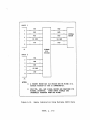
1.3 ARCHITECTURE
The PRCCI design incorporates a dual-microprocessor architecture. These
microprocessors reside on separate but identical printed circuit boards
(CPU A and CPU B). The two processor boards communicate with each other
over an internal, asynchronous, serial data channel. CPU A is the
master on this circuit and CPU B is permitted to respond only when
addressed.
CPU A is primarily responsible for communication with the
office. This includes the implementation of the office protocol on both
the normal (Jl) and standby (J2) channels, as well as the interactive
6408F, p. 1-1
maintenance session. CPU B is primarily responsible fer code line
communication and ·-ntrol of the front panel display. A ribbon cable
connects CPU 8 with c.:e intgrface board. The interface board physically
provides the processor access to the line/local inputs and outputs as
well as the discrete LEDs and alphanumeric display on the front pan4l.
This configuration allows for optimum utilization of each processor
while minimizing inter-processor communication.
1.4
FLOW OF INFORMATION
Information from an office is first received by CPU A and subjected to
lower level hardware and protocol level verification. CPU A informs CPU
a that information has been received and determines if the message is
addressed to the unit and requires further processing.
Certain classes of messages are processed directly by CPU A.
The
responses to these messages are determined by CPU A. Most classes of
messages however, require that CPU A pass the received message to CFU B
for additional verification and subsequent processing. In general, for
these messages, the response of CPU a determines the response of CPU A
to the office. CPU B may typically respond to CPU A with any buffered
information that it has at the time. This excludes certain maintenance
session messages that require specific responses and cases where
Regardless of the level of
messages fail verification by CPU B.
activity in office communication, CPU A regularly polls CPU B for
information. This allows to unit to detect internal failures and, to a
certain extent, function independently of office communication.
6408F, p. 1-2
SECTION II
INSTALLATION
2.1
APPLICATION FIRMWARE
All PRCCI applications require specific Erasable Progranunable Read Only
Memory (EPROM) sets to be installed in each CPU board. Each set is
assigned a part nwnber and is ordered separately from the PRCCI unit
itself.
Each EPROM within a set is identified by an individual part
number for manufacturing and distribution purposes.
A label on each
EPROM specifies individual EPROM part number, revision level, IC socket,
and CPU board (A or B) assignments.
When installing or removing an EPROM, keep the device aligned squarely
with the socket to prevent bending and breaking the pins. Do not
install an EPROM with bent, broken, or severely fatigued pins.
They
could break off within the socket, possibly requiring removal and
replacement of the socket. The notches in the socket and EPROM must be
aligned to avoid damage to the device when power is applied.
Random Access Memory (RAM) IC devices are necessary for operation of
each cpu beard.
The exact number required varies with each EPROM set
and may change from one revision to the next. As a general rule, any of
the IC sockets IClO, ICll, IC12, IC13, IC14, and IClS that are not used
for the EPROM set, should contain RAM devices.
IC socket IC9 must
always contain a RAM device while IC socket IC16 must always contain the
designated EPROM from the set.
2.2
CPU A CONFIGURATION
The GENISYS application of the PRCCI requires EPROM set
number
N451800-0114 installed in CPU A. This is a general purpose set, also
used in other PRCCI applications. It primarily supports corrmunication
with the office computer system and provides the maintenance session
capability.
Unless dictated by the installation, all jumpers on the board should be
placed in the standard positions. Switches SWl, SW2, SW3, SW4, SWS, and
, SW6 must be placed in the EPROM position.
Refer to the Hardware
,/ Description and Installation service manual for information on the
standard positions of these items. Any variations from the standard
positions should be reflected in site specific plans.
6408F, p. 2-1
DIP switch packs SW7 and SW8 are used to select various parameters that
affect ccmmunication with the office computer system. Programming ~f
these switches is dictated by the installation and should be reflected
in site specific plans.
SW9 is not 1Jsed and all switches should be
placed in the closed position. The PRCCI must be reset for any switch
changes to take effect.
2.2.l
eRCCI Address Selection
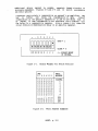
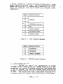
The address assigned to the PRCCI must be progratmned into SW7.
It is
entered as an eight bit, binary value between land 255 (decimal). An
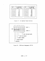
address of zero (all switches closed) is illegal. Figures 2-1 and 2-2
give the binary weighted values of the switches in SW7 and some examples
of address selections.
2.2.2
Office Baud Rate Selection
The baud rate used to communicate with the office must be programmed
into SW8.
The rate selected. is used on both the normal (Jl) and
standby/maintenance (J2) channels. Figures 2-3 and 2-4 list the switch
assignments and their options.
2.2.3
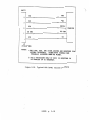
Office Transmit Key-on Delay Selection
The key-on delay time used in communication with the office must be
into
SW8.
The delay time selected is used in the
programmed
transmission of responses to the office on the both the normal (Jl) and
standby/maintenance {J2) channels.
This parameter, measured in bit
times, determines the time between the assertion of request to send
(RTS) and the beginning of data transmission. A nominal 4 bit times is
recormnended to compensate for carrier turn-on delay. The key-on delay
may have to be lengthened to compensate for any additional delays
imposed by modems, repeaters, leased circuits, or microwave equipment.
Figures 2-3 and 2-5 list the switch assignments and their options.
A typical repeater characteristically delays and shortens the carrier
key-on signal (RTS) by some pre-determined time. This time is typically
measured in bit ti.mes and is specific to the type of repeater used.
Consult documentation on the specific repeater(s) in use for the delay
ti.mes imposed. If that information is not available allow a nominal 3
bit time delay for an amplifier repeater and a nominal 7 bit time delay·
for a regenerative repeater.
2.2.4
Office Transmit Key-off Delay Selection
The key-off delay time used in cormnunication with the office must be
programmed
into
swa. The delay time selected is used in the
transmission of responses to the office on the both the normal (Jl) and
standby/maintenance (J2) channels.
This parameter, measured in bit
times, determines the ti.me between the end of data tran~ssion and the
de-assertion of request to send ('RTS) .
A nominal 4 bit times is
recommended to ensure that all data bits have transmitted on the carrier
circuit and to help prevent transients that could reduce data integrity.
The key-off delay may have to be lengthened to compensate for any
6408F, p. 2-2
additional delays imposed by modems, repeaters, leased circuits, or
microwave equipment. Figures 2-3 and 2-5 list the switch assignments
and their options.
A repeater, particularly a regenerative as opposed to an amplifier, may
tend
to
buffer
and
delay the transmission of data.
Consult
docwnentation.on the specific repeater(s) in use for the delay that it
may impose. If that information is not available allow a nominal 7 bit
time delay for a regenerative repeater. Allow a nominal 4 bit times for
carrier modulation/demodulation delay in an amplifier repeater.
8
7
6
5
4
3
2
1
OPEN• 1
CLOSE• 0
128 64 32 16 8
Figure 2-1.
4 2
1
<-- BINARY WEIGHT
IN DECIMAL
Binary Weights For Switch Positions
SW7:
8 7 6 5 4 3 2 1
PRCCI
ADDRESS
cccccccc
ILLEGAL
CCCCCCCO
CCCCCCOC
C CC C C COO
CCCCCOCC
CCCCCOCO
CCCCCOOC
CCC C COOO
CCCCOCCC
0 0 0
...
Q,,
0 0 CO
oooooooc
00000000
Figure 2-2.
1
2
3
4
5
6
7
8
...
253
254
255
PRCCI Address Examples
6408F, p. 2-3
8
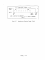
swa
7
6
5
4
3
2
l
~~~~8888
I
.
OPEN• 1
CLOSE• 0
~ F I C E BAUD RATE
~ OFFICE TRANSMIT KEY-OFF DELAY
OFFICE TRANSMIT KEY-ON DELAY
Figure 2-3.
SW8 Switch Assignments (CFO
A)
SW8:
4 3 2 1
OFFICE
BAUD RATE
SW8:
4 3 2 1
OFFICE
BAUD RATE
cccc
1200
50
OCCC
OCCO
OCOC
O COO
0 0 C C
0 0 CO
0 0 0 C
1200
2400
4800
9600
CCCO
CCOC
CCOO
COCC
COCO
COO C
COO O
75
llO
134
150
300
600
Figure 2-4.
0 0 0 0
19200
1200
1200
1200
Office Baud Rate Options
6408F, p. 2-4
swa:
OFFICE TRANSMIT
KEY-ON DELAY
8 7
cc
4 BIT TIMES
8
CO
OC
0 0
I
16
32
Figure 2-5.
2.3
SW8:
6 5
OFFICE TRANSMIT
KEY-OFF DELAY
c c
4 BIT TIMES
CO
OC
8
0 0
16
32
Office Transmit Key-on/off Delay Options.
CPU B CONFIGURATION
The GENISYS application of the PRCCI requires EPROM set
number
N451800-0105 installed in CPU B. This is a special purpose set, unique
to this application, that enables the PRCCI to communicate with a
GENISYS code system.
Unless dictated by the installation, all jumpers on the board should be
placed in the standard positions. Switches SWl, SW2, SW3, SW4, SWS, and
SW6 must be placed in the EPROM position.
Refer to the Hardware
Description and Installation service manual for information on the
standard positions of these items. Any variations from the standard
positions should be reflected in site specific plans.
DIP switch packs SW7, SWS, and SW9 are used to select various parameters
associated with field communication. The PRCCI must be reset to affect
any switch changes.
2.3.1
Code System Type
The code system type must be programmed into SW7. It must be programmed
as shown in Figure 2-6 for PRCCI to function in a GENISYS application.
2.3.2
No Response Timeout Selection
The no response timeout must be programmed into SW?.
This parameter,
measured in milliseconds, determines the length of time that the PRCCI
waits for a response to each message that it transmits.
For proper
operation, the time selected must be equal to or greater than the time
required to transmit the ETX ($F6) and receive the message header ($Fl,
$F2, or SF3) from a field response. The options available are listed in
figure 2-7.
6408F, p. 2-5
To calculate this time, consider the possible delay factors listed below
and determine the time associated with each. Select a DIF switch option
that exceeds.the total time of all delay factors. For factors measured
in bit times, refer to figure 2-13 to convert a single bit time to
milliseconds at the selected baud rate. Factors to be considered in the
no response timeout calculation include:
.~~
l. The baud rate of the circuit. This time is typically represented
in units of bits per second and should be converted to milliseconds
for this calculation. Calculate the time for 2 characters at the
given baud rate. Assume 10 bits per character unless 2 stop bits
or parity has been enabled, in which case use 11 bits per
character.
2. Maximum Field key-on delay. This delay is typically represented in
units of bit times and should be converted to milliseconds for this
calculation. Properly selected key-on delays in the field should
already take carrier delays, such as repeaters, into consideration.
3. Carrier modulation/demodulation delay. The signal modulation and
demodulation circuits internal to medium speed (300 to 1200 BPS)
FSK modems and repeaters typically impose a delay on data
throughput.
This delay i3 typically measured in bit times and is
specific to the type of equipment used. Consult documentation on
the particular type of equipment in use. If information is not
available allow a nominal 4 bit time delay for each time that the
carrier signal must be (re-)modulated and demodulated.
4. Carrier propagation delay. On open line wire a carrier signal
propagates at approximately 179,000 miles/second or about 0.56
milliseconds for every 100 miles. In tl9 cable a carrier signal
propagates at approximately 46,900 miles/second or about 2.13
milliseconds for every 100 miles.
5. Leased telephone circuits may impose additional delays.
The
characteristics and magnitude of such delays may be specific to the
supplier. Under normal circumstances this calculation should be
based on the maximum allowable delay as prescribed by current
tariff regulations.
6. Any other possible source of carrier delay, such as a microwave
link, that is unique or specific to the installation. If such a
source exists, be sure to consider the maximum delay that could be
imposed, not just an average delay.
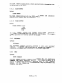
2.3.3
Baud Rate Selection
The baud rate used by the PRCCI to communicate on the
field
communication (J3) channel must be programmed into SW8. The rate
selected is used as both the normal and alternate baud rate in
communication with the field code units. Programming is dictated by the
installation and should be reflected in site specific plans.
Figures
2-8 and 2-9 list the switch assignments and their options.
6408F, p. 2-6
;
2.3.4
Stop Bit Selection
The number of stop bits used by the PRCCI to communicate on the field
communication (J3) channel must be programmed into swa. By placing(
SW8:5 in the closed position 1 stop bit is selected. By placing SW8:5
in the opened position 2 stop bits are selected. Figure 2-8 shows this
switch in the.closed position since only 1 stop bit is typically used on
GENISYS code lines installed by US&S.
The selection of 2 stop bits may become necessary when certain types of
repeaters are in use on the code line. These devices may clip and
shorten a single stop bit, preventing successful communication between
the PRCCI and the field code unit(s). For proper operation a minimum of
1.5 stop bits must be received by the PRCCI when the 2 stop bit option
has been selected.
2.3.5
Parity Enable/Disable
The use of parity on the field communication (J3) channel must be
By placing SW8:6 in the closed position parity
programmed into SW8.
generation and checking is disabled. By placing SW8:6 in the opened
position parity generation and checking is enabled. Figure 2-8 shows
this switch in the closed position since parity is not typicaly enabled
on GENISYS code lines installed by US&S.
2.3.6
Parity Selection
The type of parity implemented on the field communication (J3) channel
must be programmed into SW8 if the use of parity has been enabled. By
placing SW8:7 in the closed position odd parity is selected. By placing
SW8:7 in the opened position even parity is selected. Figure 2-8 shows
this switch in the closed position as a default since parity is not
typically enabled.
2.3.7
Transmitter Key-on Delay Selection
The transmitter key-on delay imposed by the PRCCI on the field
communication (J3) channel must be programmed into SW9. This parameter,
measured in bit times, determines the time between the assertion of
request
to
send (RTS) and the beginning of data transmission.
Typically, a nominal 4 bit times is recommended to compensate for
carrier turn-on delay.
The key-on delay may have to be lengthened to
compensate for any additional delays imposed by modems, repeaters,
leased circuits, or microwave equipment. Figures 2-11 and 2-12 list the
switch assignments and their options.
A typical repeater characteristically delays and shortens the carrier
key-on signal (RTS) by some pre-determined time. This time is typically
measured in bit times and is specific to the type of repeater used.
Consult documentation on the specific repeater(s) in use for the delay
times imposed. If that information is not available allow a nominal 3
bit time delay for an amplifier repeater and a nominal 7 bit time delay
for a regenerative repeater.
6408F, p. 2-7
2.3.9
Transmitter Key-off Delay Selection
The transmitter key-off delay imposed by the PRCCI on the field
cormnunicat-:n (J3) channel must be programmed into SW9. This parameter
determines :he tL~e between the end of data_ transmission and the
de-assertion of request to send (RTS). Typically, a nominal 4 bit times
is recormnended to ensure that all data bits have been transmitted on the
carrier circuit and to help prevent transients that could reduce data
integrity. The key-off delay may have to be lengthened to compensate
for any additional delays imposed by modems, repeaters, leased circuits,
or microwave equipment.
Figures 2-11 and 2-12 list the
switch
assignments and their options.
A repeater, particularly a regenerative as opposed to an amplifier, may
tend
to
buffer
and
delay the transmission of data.
Consult
documentation on the specific repeater(s) in use for the delay that it
may impose. If that information is not available allow a nominal 7 bit
time delay for a regenerative repeater. Allow a nominal 4 bit times for
carrier modulation/demodulation delay in an amplifier repeater.
8 7
SW7
6 5
4 3 2 1
~~~~~~~~
T
.
Figure 2-6.
OPEN• 1
CLOSE• 0
~ D E SYSTEM TYPE
NO RESPONSE TIMEOUT
SW7 Switch Assignments (CPU B)
6408F, p. 2-8
./'""""\,}
.
SW7:
8 7 6 5
NO RESPONSE
TIMEOUT (MS)
cccc
10
20
50
100
150
200
250
300
C
C
C
C
C
C
C
CCO
COC
COO
OCC
OCO
OOC
OOO
OC
OC
OC
OC
0 0
0 0
0 0
0 0
Figure 2-7.
8
swa
7
6
5
SW7:
8 7 6 5
CC
CO
OC
OO
CC
CO
0 C
0 0
350
400
450
500
750
850
1000
1250
No Response Timeout Options
4
3
2
1
~~~~BBBB
IL
NO RESPONSE
TIMEOUT {MS)
OPEN= 1
CLOSE= 0
l o o o E LINE BAUD RATE
STOP BIT SELECT
PARITY ENABLE
PARITY SELECT
RESERVED
Figure 2-8.
SW8 Switch Assignments (CPU B)
640SF, p. 2-9
SW8:
4 3 2 1
CODE LINE
SW8:
BAUD RATE
4 3 2 1
cccc
1200
1200
1200
1200
1200
150
300
CCCO
CCOC
CCOO
COCC
COCO
COOC
COO O
OC
OC
OC
OC
0 0
0 0
0 0
0 0
600
Figure 2-9.
SW8:
7 6 5
xxc
XXO
xc x
COX
0 0 X
Figure 2-10.
CODE LINE
BAUD RATE
CC
CO
OC
OO
CC
CO
0 C
0 0
1200
2400
4800
9600
1200
1200
1200
1200
Baud Rate Options
PARITY I STOP BIT
SELECTIONS
ONE STOP BIT
TWO STOP BITS
DISABLE PARITY
ENABLE ODD PARITY
ENABLE EVEN PARITY
Parity/Stop Bit Options
6408F, p. 2-10
8
6
7
5
4
3
2
1
OPEN= 1
CLOSE= 0
T
L,RANSMITTER KEY-ON DELAY
TRANSMITTER KEY-OFF DELAY
Figure 2-11.
SW9:
4 3 2 1
SW9 Switch Assignments (CPU B)
KEY-ON DELAY
(BIT TIMES)
cccc
CCCO
CCOC
CC O O
COCC
COCO
COOC
COO O
OCCC
OCCO
OCOC
O COO
0 0 CC
0 0 CO
0 0 0 C
0 0 0 0
Figure 2-12.
0
4
8
12
16
20
24
28
32
36
40
44
48
52
56
60
SW9:
8 7 6 5
cccc
CCCO
CCOC
CCOO
COCC
COCO
COOC
COO O
OCCC
OCCO
OCOC
OCOO
0 0 CC
0 0 CO
0 0 0 C
0000
KEY-OFF DELAY
(BIT TIMES)
0
4
8
12
16
20
24
28
32
36
40
44
48
52
56
60
Transmitter Key-on/off Delay Options.
6408F, p. 2-11
BAUD RATE
(BITS/SECj
150
300
600
1200
2400
4800
9600
Figure 2-13.
2.4
BIT TIME
(MS/BIT)
6.6667
3.3333
1.6667
0.8333
0.4167
0.2083
0.1042
Bit Time Table.
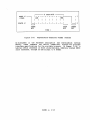
CTC OFFICE INTERFACE
The CTC office system communicates with a PRCCI over either a normal or
stand.by asynchronous, serial channel. Both are available at connectors
Jl (NORMAL) and J2 (STANDBY/MAINT), located at the rear of the unit.
The office protocol is only permitted to be active on one channel at a
time. The standby channel, when not active with the office protocol,
may be connected to an ANSI standard terminal to access the maintenance
session. This channel functions in only one mode at a time. The office
protocol, regardless of whether a maintenance session is opened or not,
always takes precedence.
Both channels utilize a word format of 1 start bit, 8 data bits, no
parity, and 1 stop bit. The baud rate is selectable with DIP switches
and both operate at the same speed.
The transmission of a character requires that the circuit transition
from an idle MARK state to the SPACE state for one bit ti.me. This first
transition is called the start bit. During the next eight bit times,
the circuit transitions between MARK and SPACE, as required, to
represent the character. The least significant bit of the character is
transmitted first.
The circuit is then forced to the MARK state for a
minimum ot one bit time. This final state is called the stop bit.
Its
primary functions are to frame the transmitted character and to ensure
that the next start bit may be recognized as a MARK to SPACE transition.
Figure 2-14 depicts the asynchronous character format utilized on the
circuit.
6408F, p. 2-12
)
8 DATA BITS
1
MARK -V - - -
I
(IDLE)
SPACE +V
r -
T -
T - T - T - T -
LSB
I
T - T - ......
, -----.
~-LL.LJ._.L_J._~-~
L--1
'---I
START
BIT
Figure 2-14.
r 1
MSB
STOP
BIT
----1. 0
'---I
START
BIT
TIME>
Asynchronous Character Format (Office)
As discussed in the Hardware Description and Installation service
manual, these channels are RS232C compatible. Figure 2-15 provides
interface specifications for the available signals. In figure 2-16, a
typical office interface is shown using multiple, remotely located PRCCI
units connected, through an EIA bridge, to a modem.
6408F, p. 2-13
PIN
STATE
VOLTAGE
TXD
TRANSMIT DATA
2
MARK
SPACE
-3 TO -15
+3 TO +15
OUTPUT
RXD
3
MARK
SPACE
-3 TO -15
+3 TO +15
INPUT
RTS
REQUEST TO SEND
4
OFF
ON
-3 TO -15
+3 TO +15
OUTFUT
CTS
CLEAR TO SEND
5
OFF
ON
-3 TO -15
+3 TO +15
INPUT
DSR
DATA SET READY
6
OFF
ON
-3 TO -15
+3 TO +15
INPUT
SIGNAL GROUND
7
---
0
---
OCD
DATA CARRIER DETECT
a
OFF
ON
-3 TO -15
+3 TO +15
INPUT
20
OFF
ON
-3 TO -15
+3 TO +15
OUTPUT
SIGNAL·
RECEIW DATA
DTR
DATA TERMINAL READY
DIRECTION
NOTES:
1) VOLTAGES REFERENCED TO SIGNAL GROUND
2) DATA STATE IS UNDEFINED IN TRANSITIONAL REGION
BETWEEN -3 AND +3 VOLTS.
Figure 2-15.
RS-232C Compatible Interface Specifications
6408:', p. 2-14
---""
PRCCI 1
TXD
>>
2
»
«
RXD
>>
3
RTS
>>
4
>>
DCD
<
>>
RTS
«
>>
»
<
SG GND
DCD
<
>>
8
«
RXD
SG GND
7
TXD
Jl
>>
<
NORMAL
MODEM
<
<<
<
NORMAL
EIA
BRIDGE
PRCCI 2
TXD
2
>>
RXD
3
4
>>
»
RTS
SG GND
7
8
>>
»
DCD
«
«
«
«
«
Jl
NOTES:
1) A STANDBY MODEM AND EIA BRIDGE MAY BE WIRED IN A
SIMILAR FASHION TO THE J2 CONNECTOR(S).
2) ONLY TXD, RXD, AND SIGNAL GROUND ARE REQUIRED FOR
MINIMAL INTERFACE. OTHER INPUT SIGNALS ARE
INTERNALLY ASSERTED WHEN NOT WIRED.
Figure 2-16.
Remote Installation Using Multiple PRCCI Units
6408F, p. 2-15
2.5
CODE LINE INTERFACE
!he int~rface to the code line i:~mmunication equipment is provid~d at
connector J3 (FIELD COMM), located at the rear of the unit. It may be
configured as either an RS-232C level or a current loop interface,
depending
upon the type of communication equipment used at the
installation ..
The RS-232C level interface is recommended and should be used in all
installations whenever possible. It is, by far, the most cormnon carrier
interface and allows a wide variety of data monitoring equipment to be
used on the communication circuit. Figure 2-15 provides specifications
for this interface. Figure 2-18 shows a typical EIA level interface
between a GENISYS PRCCI and carrier equipment.
Where only TTL level carrier is available, the current loop option
provides a suitable interface but is not necessarily compatible with
most communication test equipment. Figure 2-19 shows a typical TTL
level
interface
between a GENISYS PRCCI and carrier equipment.
Additional interfacing information is provided
in
the
Hardware
Description and Installation service manual.
The word format utilized on this channel is DIF switch selectable with 1
start bit, 8 data bits, an optional parity bit, and an option for 1 or 2
stop bits. The baud rate is also DIP switch selectable.
Both the
normal and alternate rates are determined by the switch selection.
The transmission of a character requires that the circuit transition
from an idle MARK state to the SPACE state for one bit time. This first
transition is called the start bit. During the next eight bit times,
the circuit transitions between MARK and SPACE, as required, to
represent the character. The least significant bit of the character is
transmitted first.
If enabled, the parity bit is transmitted next.
Parity is an error detection mechanism where either an even or odd
n1..1rr.ber of MARK bits are required within a character. The state of the
parity bit is determined by the type of parity selected and the number
of preceding data bits transmitted as a MARK. For even parity, the
parity bit is manipulated to result in an even number of MARK bits. Odd
parity results in an odd number of MARK bits to occur. A character is
terminated with one or more stop bits. Stop bits force the circuit to
the idle MARK state and serve to frame the transmitted character to
ensurg that the next start bit may be recognized as a MARX to SPACE
transition.
Figure 2·17 depicts the asynchronous character format
utilized on the circuit.
2.6
LOCAL CONTROLS AND INDICATIONS
All of the line/local outputs and inputs are available to the office as
local controls and indications.
The use of these is dictated by
installation requirements and should be reflected in site specific
plans.
Detailed information and specifications of the line/local
interface are available in the Hardware Description and Installation
service .:nanual.
6408F, p. 2-16
/~
J
8 DATA BITS+ PARITY
1
MARK -V ~ -
( IDLE)
SPACE
·
+v
LSB
Il___J
T -
T -
T -
T -
T -
T -
MSB
T -
-,- - - -
~- ~-~- ~-~- ~- ~- ~-~
l--1 - J
START
BIT
NOTE:
I
T -
L-l O
t__J
STOP
START
BIT (S)
BIT
PARITY BIT IS GENERATED ONLY IF PARITY IS ENABLED.
TIME>
Figure 2-17.
Asynchronous Character Format (Field)
6408F, p. 2-17
r 1
---\
l'RCCI
]
TXD
2
TXD
>
<
>>
<
>
<
>
<
>
<
RXD
3
RXD
RTS
4
KEY-ON
SG COM
SG GND
7
DCD
8
CARRIER
CD
J3
(FIELD COMM)
NOTES:
1) ONLY TXD, RXD, AND SIGNAL GROUND ARE REQUIRED FOR
MINIMAL INTERFACE. OTHER INPUT SIGNALS ARE
INTERNALLY ASSERTED WHEN NOT WIRED.
2) RTS IS NECESSARY ONLY IF PRCCI IS REQUIRED TO
KEY CARRIER ON TO TRANSMIT.
Figure 2-18.
Typical EIA level Carrier Interface
6408F, p. 2-18
PRCCI .
CARP.IER
TXD
+ 12V
+
12
TX
TXD -
13
RXD
+
RX
15
RXD -
RX COM
RTS
KEY-ON
16
4
SG COM
SG GND
7
DCD
CD
I
8
NO CONNECTION
I
J3
(FIELD COMM)
NOTES:
1) CPU B JUMPERS J4 AND J7 MUST BE IN B-C POSITION
TO SELECT PASSIVE CURRENT LOOP INTERFACE FOR J3.
2) ALL MODEM CONTROL SIGNALS ARE EIA LEVEL INPUTS
AND OUTPUTS. DCD INPUT MUST NEVER BE CONNECTED
TO A TTL LEVEL SOURCE THAT COULD TAKE IT TO OV.
RTS OUTPUT IS COMPATIBLE WITH TTL LEVEL INTERFACE
PROVIDED DE-ASSERTED STATE OF-VIS FUNCTIONALLY
EQUIVALENT TO OV.
2) RTS AND SG GND ARE NECESSARY ONLY IF PRCCI IS
REQUIRED TO KEY CARRIER ON TO TRANSMIT.
Figure 2-19.
Typical TTL Level Carrier Interface
6408F, p. 2-19
SECTION III
OPERATION
3.1
OVERVIEW
When power is first applied or the master reset switch is pressed, each
cpu board independently executes self-tests to verify the integrity of
the EPROM set and RAM. Following successful completion of these tests,
the DIP switches are read, the message EMULATE GENISYS is displayed on
the front panel, and the PRCCI waits for the office to establish
communication.
In the event that one of the self-tests fail, the watchdog timer is
allowed to trip and reset the cpu board. This is indicated by LEDl
flashing on the failed cpu board. Should an error message be displayed,
refer to section 3.6 for corrective action.
Briefly, the office should initialize the PRCCI and configure it to the
installation. The office then requests indications from all stations on
the code line through a sequence of individual recall requests.
When
there are no pending control or recall requests to transmit the PRCCI
independently polls the field code units in a round robin fashion. This
is indicated by only a station address displayed on the front panel.
3.2
FUNCTION LED DESCRIPTIONS
Seven of the eight LEDs in this group are software controlled status
indicators for various functions under software control of the PRCCI.
The remaining LED is a hardware driven power indicator.
A brief
description of each LED and its associated function is given below.
FUNCTION XMT
This LED denotes a FIELD TRANSMIT function.
When illuminated it
indicates that the PRCCI is transmitting data to the field
communication equipment.
FUNCTION REC
This LED denotes a FIELD RECEIVE function.
When
indicates
that the PRCCI is receiving data
communication equipment.
6408F, p. 3-1
illuminated, it
from the field
FUNCTION GM
This LED denotes a GOOD MESSAi,E function.
It reflects message
traffic between the cpu boards. A flash rate of once per second
indicates normal internal polling of CFU B by CPU A. A faster rate
indicates message traffic between the PRCCI and the office.
FUNCTION ERR
This LED denotes a HOST ERROR function.
When illuminated, it
indicates that an error has been detected in communication with the
office.
It
remains
illuminated until
communication
is
re-established with the office.
FUNCTION A
This LED denotes an ADDRESS ACCEPT function. When illuminated,
indicates that the PRCCI is being addressed by the office.
it
FUNCTION B
This LED denotes a STANDBY PORT ACTIVE function. When illuminated,
it indicates that the office is communicating with the PRCCI over
the standby channel.
FUNCTION C
This LED denotes a MAINTENANCE SESSION ACTIVE function.
When
illuminated, it indicates that a maintenance session is opened.
FUNCTION O
This LED is a hardware indication of the 5 volt output
PRCCI power supply and should be illuminated constantly.
3.3
from the
OUTFUT LED DESCRIPTIONS
The LEDs in this group are state indicators for each of the local
control outputs.
While the outputs themselves are under software
control, these LEDs reflect the actual hardware state of the output
module control circuits.
They should normally remain dark and flash
only when the associated local control is delivered.
3.4
INPUT LED DESCRIPTIONS
The LEDs in this group are hardware driven state indicators for each of
the local indication inputs.
When illuminated, they indicate that
energy is applied to the associated input.
6408F, p. 3-2
,-)
3.5 OPERATIONAL MESSAGES
EMULATE GENISYS
This message is displayed upon power-up, reset, and initialization
from the office computer system. Following initialization, this
message is normally replaced with other operational messages or
station addresses are displayed as the polling cycle progresses.
CONTROL NN
This message indicates that the PRCCI is transmitting a control to
station address NN.
The message is displayed during the control
transmission and any checkback, and execute sequence supported by
the GENISYS code system.
RECALL NN
This message indicates that the PRCCI is recalling indications from
station address NN.
KEY MARK
This message indicates that the PRCCI is in line maintenance mode,
transmitting a rest state of MARK to the code line communication
equipment.
This capability is
only
provided
through
the
maintenance session.
KEY SPACE
This message indicates that the PRCCI is in line maintenance mode,
transmitting an inverted rest state (norest) of SPACE to the code
line communication equipment. This capability is only provided
through the maintenance session.
KEY DUTY CYCLE
This message indicates that the PRCCI is in line maintenance mode,
transmitting a 50% duty cycle to the code line communication
equipment.
This capability is
only
provided through
the
maintenance session.
CODE LINE NORMAL
This message indicates that line maintenance mode has just been
turned off and that normal code line operation has not yet resumed.
There is typically a short delay in returning to normal operation
that varies with the code line baud rate. This message will remain
on the front panel if the PRCCI is not initialized.
6408F, p. 3-3
3.6
ERROR MESSAGES
~
e
This error flag may appear on the front panel immediately to the
right of the station address. It indicates that an error condition
has been-declared for the station due to a hardware level error
detected in the last response fro~ the station. Hardware level
errors include parity, framing, or overrun (loss of data) errors.
A limited number of these errors over a period of time is to be
expected and does not necessarily indicate improper operation of
the code line.
Should the number of these errors reach an
unacceptable level, it should be considered an indication of poor
line quality, cormnunication equipment failure, or field unit
failure.
M
This error flag may appear on the front panel immediately to the
right of the station address.
It indicates that a monitor
condition has been declared for the station due to repeated
protocol or hardware level errors. Protocol level errors include
an illegal message header, illegal CRC-16, illegal message length,
illegal station address, illegal responses, control checkback
errors, and no response timeouts.
A limited number of these errors over a period of time is to be
expected and does not necessarily indicate improper operation of
the code line.
Should the number of these errors reach an
unacceptable level, it should be considered an indication of poor
line quality, communication equipment failure, or field unit
failure.
This error flag may appear on the front panel immediately to the
right of the station address. It indicates that a failed condition
has been declared for the station due to repeated protocol or
hardware level errors. This condition indicates either a failure
of the communication circuit or equipment or a failure of the field
unit.
CONTROL ERR
This message indicates that an improperly formatted control request
has been received from the office.
Noanally this reflects a
possible problem in the office and should never occur with an
in-service installation.
RECALL ERR
This message indicates that an improperly formatted recall request
has been received from the office.
Normally this reflects a
possible problem in the office and should never occur with an
in-service installation.
6408F, p. 3-4
ADDRESS ERR
This messaae in~ic~t~s th~t ~n ill~gal st~tion ~1dr~ss
was
specified in either an control or recall request from the office.
The requested station address is not permitted to be zero or to
exceed the highest address polled. This may reflect a possible
problem in the office and should never occur with an in-service
installation.
INVALID INIT MSG
An incorrect initialization message was received from the office.
The message passed communication hardware checks and protocol level
checks, but the contents of the message do not
meet
the
requirements of the GENISYS application. Once the PRCCI receives
an invalid initialization message, it ceases normal code line
operation and requests initialization from the office.
This may reflect a possible problem in the office or that the PRCCI
is not connected to the office through the correct communication
channel.
This error should never occur with an
in-service
installation.
NO CODE TYPE
No code type has been programmed into DIP switch SW7 on CPU B. The
PRCCI allows the watchdog timer to trip and reset CPU B until the
condition is corrected. Refer to Section 2.3 (CPU B Configuration)
for programming information.
WRONG CODE TYPE
The wrong code system type has been programmed into DIP switch SW7
on CPU B.
The PRCCI allows the watchdog timer to trip and reset
CPU B until the condition is corrected.
Refer to
CPU
B
configuration section 1.4 for programming information.
INTERNAL ERR
This message indicates that CPU B detected errors in communication
with CPU A. While a limited failure of communication hardware on
CPU B could result in this error, the typical cause is a hardware
or software failure of CPU A. This condition should never occur
with an in-service installation.
6408F, p. 3-5
SECTION IV
OFFICE INFORMATION EXCHANGE
4.1
OVERVIEW
The scheme for communication with the office computer system is similar
to that used on a half duplex code line circuit where the office is the
master to one or more slave PRCCI units. The protocol is designed to
complement that used by the Union Switch & Signal GENISYS Non-vital
Logic Emulator. This permits multiple PRCCI and GENISYS units to
co-exist on the same communication circuit. Any GENISYS units must
appear as slaved field code units.
All conversations on this circuit are initiated by the office and only
the addressed unit is permitted to respond. If the unit detects an
error in decoding a message, the error is implied by the lack of a
response.
The office attempts a limited number of retries on messages
when no response is seen or an error is detected in the response.
4.2
PHILOSOPHY AND SECURITY
The protocol uses modified binary characters to frame messages that are
designed to lend themselves to hexadecimal interpretation. Characters
in the range of $FO through $FE are reserved as unique control
characters.
The character $FF is illegal since it is commonly created
on noisy data channels. Data security is provided in the form of a
CRC-16 checksum.
The generator polynomial is the standard CRC-16
polynomial:
16
15
2
X + X + X +1
Characters in the range of $00 to $EF are sent as is, in a single byte.
A character in the range of $FO through $FF is sent as a sequence of two
bytes. This sequence consists of the data escape character $FO followed
by the low order nibble (right hex digit) of the original character.
The receiver of any message containing this sequence must always
logically OR the two characters and treat the result as a single
character.
Every message starts with a function specific header character (in the
range of SFl through $F5 or SF7 through $FE) followed by a unit address.
Any data, if applicable to the function, then follows. The data portion
is function specific and may vary in length. Following the data is the
CRC-16 then a $F6 terminator character (End-of-Text or ETX). The CRC-16
is generated from the header, address, and data portion prior to any
possible data escape sequences being introduced.
Only the message
6408F, p. 4-1
header and terminator
escape sequence.
c~~=acters
are excluded from any possible data
!n general, messages are -~ssified according to function with a unique
character for ~ach cla~s.
Certain classifications employ
header
auxiliary header characters appearing after the address.
These denote
specific functions within a classification which contains multiple
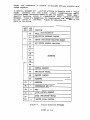
messages. Figure 4-1 swmnarizes, by classification, the messages sent
by the office to the PRCCI. Figure 4-2 summarizes those sent by the
PRCCI to the office.
MSG
HOR
AUX
HDR
FUNCTION
AO
PRCCI INITIALIZATION
Al
INDICATION DATABASE REQUEST
A4
STATUS INDICATION REGISTER REQUEST
AS
SET STATUS CONTROL REGISTER
F7
A6
A7
A8
RESERVED
A9
AA
F8
AB
F9
FA
FB
FC
FD
FE
AC
CONTROL REQUEST
AD
INDICATION RECALL
A.E
EXECUTE CONTROL
Ar
RESERVED
--
RESERVED
----
--
--
ACKNOWLEDGE AND POLL
POLL
LOCAL CONTROL REQUEST
LOCAL INDICATION RECALL
EXECUTE LOCAL CONTROL
Figure 4-1.
Office Generated Messages
6408F, p. 4-2
MSG
AUX
~R
HOR
FUNCTION
Fl
--
ACKNOWLEDGE
F2
--
LOCAL INDICATION
F3
---
LOCAL CONTROL CHECKBACK
A2
INDICATION
A3
CONTROL CHECKBACK
F4
FS
STATUS INDICATION REGISTER DATA
Figure 4-2.
4.3
PRCCI Generated Messages.
OFFICE GENERATED MESSAGES
This section discusses the function and implementation of messages
exchanged between an office computer system and a GENISYS PRCCI. The
possible responses are given for messages generated by an office. These
are listed in order from the highest priority to the lowest.
Each message must pass a variety of hardware and protocol level checks
before it may be processed. The lower level hardware checks verify the
line integrity, character framing, and that no data overrun has occured
(loss of data).
A series of protocol checks progressively verify any
CRC-16, the message header, unit address, and any auxiliary header.
Each message is then subject to specific edit checks to verify that the
contents meet the requirements of the application and the installation.
4.3.1
Poll
The poll message is generated to allow the PRCCI to return any new or
changed information from its database. This message has both a secure
and non-secure format. The secure format contains a CRC-16 while the
non-secure does not. The format used is determined by the SENSEC flag
in Status Control Register 1. Valid responses from the PRCCI include:
1.
2.
3.
4.
4.3.2
SIR data
Indication
Local indication
Acknowledge (ACK)
Acknowledge And Poll
The acknowledge and poll message is generated to acknowledge data from
the PRCCI and to poll for any additional information. All messages from
the PRCCI that contain data must be acknowledged by the office.
Until
acknowledged, the PRCCI assumes the office failed to receive the last
6408F, p. 4-3
response, and will re-transmit it in subsequent conversations.
In
su.bsequent conversations a higher priority response may take precedence
but no loss of data occurs.
-~-\
f
PRCCI Initialization
4.3.3
The PRCCI initialization message is the primary mechanism used by the
office
to
configure
a PRCCI to a specific installation.
The
capabilities of a PRCCI are limited until the unit is initialized by the
office.
This message supplies the unit with parameters to be used in
cormnunication with both the office and field.
These parameters are
described in the following sections. Valid responses from the PRCCI
include:
1.
2.
4.3.3.1
SIR data
Acknowledge (ACK)
Maximum Indication Records Per Message
This parameter determines the maximum number of buffered indication
records that may be returned to the office in a single indication
message. A record represents a single indication message from a field
code unit.
Adjustment of this parameter not only affects operation of
the PRCCI but may also affect the perceived performance of the office.
Thi3 parameter must be set between 1 and 8. In general, the slower the
effective rate at which the PRCCI is polled the higher this parameter
should be. A single unit connected directly to the office through a
dedicated channel may have this parameter set relatively low (1 or 2).
Multiple units that share a communication channel to the office should
have this parameter set higher to compensate for the effectively slower
polling rate.
4.3.3.2
Maximum Control Queue Entries
This parameter determines the maximum number of control and recall
requests that may be buffered by the PRCCI at any one time. Normally
the office is capable of-generating such requests at a faster rate than
which the PRCCI is able to transmit them to the the field. This
parameter must be set between 1 and 8.
4.3.3.3
Maximum Station Address
This parameter determines the highest station address polled by the
PRCCI. The PRCCI also uses this parameter to verify the station addJ:ess
in control and recall request3 from the office.
The GENISYS PRCCI
application restricts the highest station address to 127.
4.3.3.4
Number Of Station Retries Per Set
This parameter determine3 the number of single retries in a retry set.
Primarily, it dictates the number of times that the PRCCI may retry a
transmission before declaring an error monitor condition for a field
6408F, p. 4-4
code unit.
4.3.3.5
This parameter must be set between 1 and 5
Number Of Station Retry Sets
This parameter determines the number of retry sets that the PRCCI must
exhaust before declaring a failure condition for a field code unit. It
must be set between 1 and S.
4.3.3.6
Maximum Control Byte Number
This parameter determines the highest control byte number that may be
specified in a control request from the office. The GENISYS PRCCI
application restricts each field code unit to a maximwn of 32 control
bytes and assumes that those bytes are addressed as O through 31. The
GENISYS EO control byte, processed internally by the PRCCI, is not
subject to this restriction.
4.3.3.7
Maximum Indication Byte Number
This parameter determines the highest indication byte number that may be
received from a field code unit and as well as returned to the office.
The GENISYS PRCCI application restricts each field code unit to a
maximum of 32 indication bytes and assumes that those byte are addressed
as O through 31. Regardless of the selection for this parameter, the
GENISYS EO indication byte is accepted in a field indication message and
is also passed in an office indication message.
4.3.3.8
EO Control Byte Mask
This parameter instructs the PRCCI how to configure the EO control byte
of each field code unit. The use of the EO byte is explained in more
detail section 5.6.
4.3.4
Set Status Control Register
The set status control register (SCR) message is a secondary mechanism
used by the office to initialize, dynamically alter, or otherwise
maintain certain operating characteristics.
The
characteristics
determined by the status control registers may be altered without
re-initialization of the PRCCI. Section 4.5 describes the registers and
the characteristics that they control. Valid responses from the PRCCI
include:
1.
2.
3.
4.
SIR data
Indication
Local indication
Acknowledge (ACK)
6408F, p. 4-5
4.3.5
Status Indication Register Request
The sr ~tus indication regi.st~r (SIR) r~quest message is 1enerated to
examine the current contents of all such registers :etined by the
GENISYS PRCCI application. Valid responses from the FRCCI include:
SIR data
Acknowledge {ACK)
1.
2.
4.3.6
Indication Database Request
The indication database request message is generated by the office to
update
its own indication database.
This function provides the
capability for the office to update itself without having to place
recall and unchanged indication traffic on the field code line.
Indication data generated in response to this request appears to the
office as nonnal indication messages. Valid responses from the PRCCI
include:
1.
SIR data
2.
3.
4.
Indication
Local indication
Acknowledge (ACK)
4.3.7
Local Control Request
The local control request message is generated to request that the PRCCI
deliver local controls. If control checkback is enabled the only legal
response is a local control checkback message.
When check.back is
disabled, valid responses from the PRCCI include:
1.
2.
3.
4.
4.3.8
SIR data
Indication
Local indication
Acknowledge (ACK)
Execute Local Control
The execute local control message is generated to execute a local
control request that had been previously verified with a local control
checkback message from the PRCCI. This message must irllnediately follow
the local control check.back or the office must repeat the sequence
beginning with a retry of the local control request.
This message is
illegal if control checkback is disabled. Valid responses from the
FRCCI include:
4.3.9
1.
SIR data
2.
Acknowledge (ACK)
Local Indication Recall
The local indication recall message is generated to request the current
local indications from the PRCCI.
The PRCCI is only permitted to
respond with:
6408F, p. 4-6
,~
J
1.
2.
4.3.10
SIR data
Local indication
Control Request
The control request message is generated to request that the PRCCI
transmit a control message to the field. This message specifies the
field code unit address, the number of control bytes in the request, as
well as each control byte number and current control byte data. If
control checkback is enabled the only legal response is a control
checkback message. When checkback is disabled, valid responses from the
PRCCI include:
1.
2.
3.
4.
4.3.11
SIR data
Indication
Local indication
Acknowledge (ACK)
Execute Control
The execute control message is generated to execute a control request
that had been previously verified with a checkback message from the
PRCCI. This message must immediately follow the control checkback or
the office must repeat the sequence beginning with a retry of the
control request. This message is illegal if control checkback is
disabled. Valid responses from the PRCCI include:
1.
2.
4.3.12
SIR data
Acknowledge (ACK)
Indication Recall
The indication recall message is generated to request that the PRCCI
recall current indications from the specified field code unit. The
indications received by the PRCCI in response to the recall are always
returned to the office regardless of whether or not there is a change in
state. Valid responses from the PRCCI include:
1.
2.
3.
4.
4.4
4.4.1
SIR data
Indication
Local indication
Acknowledge (ACK)
PRCCI GENERATED MESSAGES
Local Control Checkback
The local control checkback message is generated as part of the
verification procedure for local control delivery. It is only legal ~n
response to a local control request from the office when checkback is
enabled.
A proper checkback response returns the same control byte
number and control byte data as requested.
6408F, p. 4-7
4.4.2
Control Checkback
The control che~kbar.K me!!~ge is g~~erat~d ~s part of the verification
procedure for control transmission to the field. It is only legal in
response to a control request from the office when checkback is enabled.
A proper checkback response returns the same field code unit address,
and control information as requested.
4.4.3
Status Indication Register Data
The SIR data message is generated to return SIR information to the
office.
SIR information is returned only when changes-occur or upon
request from the office.
4.4.4
Indication
The indication message is generated to retu~n field indication data to
the office.
Normally, ·indications are returned only when a change in
state is detected or when the office has requested a recall.
This
message may contain multiple indication records where each record is
associated with a particular field code unit. The PRCCI initialization
message specifies the maximum n~er of records that may appear in a
message. An indication record specifies the field code unit address,
the number of indication bytes in the record, as well as each indication
byte number and current indication byte data.
The indication message is also used to report field code unit status
information to the office.
Such information includes monitor and
failure conditions that may be declared or automatically cleared up by
the ?RCCI.
4.4.5
Local Indication
The local indication ~esssage is generated to return local indication
data to the office. Local indications are returned only when a change
in state is detected or in response to a recall from the office.
4.4.6
Acknowledge
The acknowledge message is generated as a response when the PRCCI has no
data to return to the office. This message has only a non-secure format
that does not contain a CRC-16.
4.5
STATUS CONTROL AND INDICATION REGISTERS
Certain operating characteristics
internal status registers. These
computer system and allow the
characteristics as well as sense
detected by the FRCCI.
are controlled and indicated through
registers are accessible by the office
office to dynamically maintain the
and/or clear possible error conditions
6408F, p. 4-8
There are sixteen registers available; addressed O through 15.
While
the
function
of
each register is consistent across all PRCCI
applications, not all registers aro. used by all of the ~pplic~tj~ns.
This section describes each register implemented by the GENISYS PRCCI
application.
Those not described are accessible but perform no
function.
4.5.1
Status Control Register O
Figure 3-3.
SCRO Flags
SNOIDB - Clear the no indication database flag
SCTBSY - Clear control queue busy flag.
control request queue.
SINQOV
Forces the PRCCI to
Clear indication queue overflow flag.
not cleared of data.
clear
The indication queue
its
is
SDETER - Clear PRCCI detected error flag.
4.5.2
Status Indication Register O
SNOIDB SMAINT SCTERR SCTBSY SINQOV SDETER SLNERR SRCINI
Figure 3-4.
SIR O Flags
SNOIDB - No indication database. This flag is cleared by the office to
signify that indications from all stations on the code line
have been received. The PRCCI normally sets this flag upon
reset or initialization.
SMAINT - Maintenance session open. This flag is set to indicate that
maintenance session is opened.
a
SCTERR - Control request error. This flag is set to indicate· that an
error was detected while performing edit checks on a previous
control request from the office.
It remains set until the
office generates an acceptable control request.
SCTBSY - Control queue busy. This flag is set to indicate that the
maximum number of control requests have been queued by the
office. The flag is cleared automatically once the control
queue is sufficiently emptied to accept additional requests.
SINQOV - Indication queue overflow. This flag is set to signify that
the field indication queue has overflowed. Previous indication
data is lost since the queue is automatically cleared and the
6408F, p. 4-9
most recent indication is inserted. The flag is cleared on
reset, initialization, or by request of the office.
-~-,__1
}
SDETER - PRCCI detected error.
Reserved flag.
SLNERR - Code line error. This flag is set to indicate tha~ an error
was -detected on the code line. This flag is automatically
cleared once communication is re-established on the code line.
SRCINI - PRCCI initialization request. This flag is set to request
initialization from the office. It may only ever be cleared by
the office with a valid initialization message.
4.5.3
Status Control/Indication Register l
SFLTRI SENCOD SENSEC SENCBC SALNRT SATPA.R SRBADI
Figure 3-5.
SCR/SIR l Flags
SFLTRI - Enable indication change filter. This flag is set to filter~
only changed indications to the office.
If cleared, all.
indications, as received, are passed to the office. It is setf
on reset and initialization.
SENCOD - Enable code line communication.
This flag is
primarily
intended for use on polling code systems. Only when this flag
is set is the PRCCI permitted to conmunicate with the fields.
It is cleared on. reset, initialization, and during certain
maintenance functions.
SENSEC - Enable secure poll. This flag is set to force the PRCCI to
accept only secure poll messages from the office. If this flag
is cleared, the PRCCI will accept either secure or non-secure
polls. It is cleared on reset and initialization.
SENCBC - Enable control checkback. This flag is set to enable control
check.back mode· for all control and local control requests from
the office. It is cleared on reset and initialization.
SALNRT - Enable alternate line rate. This flag is set to instruct the
PRCCI to use the alternate line rate for field colllllUnication.
It is normally cleared on reset and initialization to default
to the normal line rate. The normal line rate is specified in
SCR/SIR 3 while the alternate is specified in SCR/SIR 4.
SATPAR - Enable alternate timing parameters.
SRBADI - Return bad indications.
Reserved flag.
Reserved flag.
6408F, p. 4-10
4.5.4
Status Control/Indication Register 2
Reserved for future use.
4.5.5
Status Control/Indication Register 3
These registers typically select and indicate the normal baud rate for
field communication. The GENISYS PRCCI application does not permit the
office to alter this DIP switch selected parameter.
4.5.6
Status Control/Indication Register 4
These registers typically select and indicate the alternate baud rate
for field communication.
The GENISYS PRCCI application assigns the
alternate rate to be the same as the DIP switch selected normal rate.
As with the normal rate, the office is not permitted to alter this
parameter.
6408F, p. 4-11
SECTION V
FIELD INFORMATION EXCHANGE
5.1
OVERVIEW
The PRCCI communicates with one or more GENISYS field code units over a
half duplex code line.
The PRCCI is the master on this circuit and
initiates all conversations. Only the addressed field unit is permitted
to respond.
If the unit detects an error in decoding a transmission,
the error is implied by the lack of a response. The PRCCI attempts a
limited number of retries on messages when no response is seen or an
error is detected in the response.
5.2
PHILOSOPHY AND SECURITY
The protocol uses modified binary characters to frame messages that are
designed to lend themselves to hexadecimal interpretation. Characters
in the range of $FO through $FE are reserved as unique control
characters.
The character $FF is illegal since it is commonly created
on noisy data channels. Data security is provided in the form of a
CRC-16 checksum.
The generator polynomial is the standard CRC-16
polynomial:
16
15
2
X + X + X + 1
Characters in the range of $00 to $EF are sent as is, in a single byte.
A character in the range of $FO through $FF is sent as a sequence of two
bytes. This sequence consists of the data escape character $FO followed
by the low order nibble (right hex digit) of the original character.
The receiver of any message containing this sequence must always
logically OR the two characters and treat the result as a single
character.
Every message starts with a function specific header character (in the
range of $Fl through $F3 or $FA through $FE) followed by a unit address.
Any data, if applicable to the function, then follows. The data portion
is function specific and may vary in length. Following the data is the
CRC-16 then a $F6 terminator character (End-of-Text or ETX). The CRC-16
is generated from the header, address, and data portion prior to any
possible data escape sequences being introduced.
Only the message
header and terminator characters are excluded from any possible data
escape sequence.
6408F, p. 5-1
In general, messages are classified according to function with a unique
header character for each class.
Figure 5-1 summarizes the message
headers u.seti by the PRCCI in transmissions to GENISYS field code units.
Figure 5-2 summarizes those used by GENISYS units to respond to PRCCI
transmissions.
HEADER
MESSAGE FUNCTION
F7
rs
RESERVED
F9
FA
ACKNOWLEDGE AND POLL
FB
POLL
re
CONTROL REQUEST
FD
INDICATION RECALL
FE
EXECUTE CONTROL
Figure 5-1.
HEADER
MESSAGE FUNCTION
Fl
ACKNOWLEDGE
F2
INDICATION
F3
CONTROL CHECKBACK
Figure 5-2.
5.3
PRCCI Generated Messages
GENISYS Generated Messages.
PRCCI GENERATED MESSAGES
of
This section discusses the function and implementation
messages
exchanged between a GENISYS PRCCI and a GENISYS field code unit. Each
message must pass a variety of hardware and protocol level checks before
it may be processed. The lower level hardware checks verify the line
integrity, character framing, and that no data overrun has occured (loss
of data).
The protocol level checks progressively verify any CRC-16,
the message header, unit address, and any data portion of each message.
6408F, p. 5-2
KC-'\
\
5.3.1
Poll
The poll message is generate~ t~ all~w a GENISYS to return any n~w or
changed indication information.
This message has both a secure and
non-secure format. The secure format contains a CRC-16 while the
non-secure does not. The format used is determined by the secure poll
flag in the EO control byte. Either an indication or acknowledge is a
valid response to this message.
5.3.2
Acknowledge And Poll
The acknowledge and poll message is generated to acknowledge an
indication from a GENISYS and to poll for any additional information.
All indication messages from a GENISYS must be acknowledged by the
PRCCI. Until acknowledged, the unit assumes the PRCCI failed to receive
the last response, and will re-transmit it in subsequent conversations.
As with a poll message, either an indication or acknowledge is a valid
response to this message.
5.3.3
Indication Recall
The indication recall message
indications from a GENISYS.
with an indication message.
5.3.4
is generated to request all current
The GENISYS is only permitted to respond
Control Request
The control request message is generated to request that a GENISYS
deliver the specified control data.
The PRCCI is only capable of
transmitting a control message upon request from the office and does not
attempt to filter changes in control data. It transmits all control
data requested by the office, regardless of whether or not there is
actually a change of state.
Under normal circumstances, only the
control data specified in a control request is transmitted.
The
exception to this is when the PRCCI detects that a station's control
database is incomplete. When this occurs, the PRCCI waits for the next
office control to that station and proceeds to transmit all valid
control bytes regardless of whether or not all were requested.
If
control checkback is enabled the only legal response is a control
checkback message. When checkback is disabled either an indication or
acknowledge is a valid response to this message.
5.3.5
Execute Control
The execute control message is generated to request that a GENISYS
execute a control request that had been previously verified with a
checkback message from the unit. This message must immediately follow
the control checkback or the PRCCI must repeat the sequence beginning
with a retry of the control request. This message is illegal if control
checkback is disabled. Either an indication or acknowledge is a valid
response to this message.
6408F, p. 5-3
5.4
GENISYS GENERATED MESSAGES
5.4.l
Control Checkback
The control checkback message is generated as part of the veri:ication
procedure for control delivery.
It is only legal in response to a
control request from the PRCCI when checkhack is enabled.
A proper
checkback response returns the byte number and data for each control
byte requested.
5.4.2
Indication
The indication messsage is generated to return indication data to the
PRCCI. Indications are normally returned only when a change in state is
-~ detected or in response to a recall from the PRCCI.
Excluding the EO
indication byte, an indication message may not contain an indication
byte num.ber - ·· 1t exceeds the maximum specified by the office at
initializatic
5.4.3
Acknowledge
The acknowledge message is generated as a response when a GENISYS has no
data to return to the PRCCI. This message has only a non-secure for:mat
that does not contain a CRC-16.
5.5
POLLING CYCLE DESCRIPTION
The PRCCI polls a pre-determined number of stations in a round robin
fashion.
To minimize delays in the polling cycle, due to errors or no
response timeouts, failed stations are not polled. At the end ot each
polling cycle a recall is transmitted for a failed station in an attempt
to eventually establish co~unication with all possible stations.
Office requests for controls
:ecalls take priority and may interrupt
the normal polling cycle. Wh·
Ll office requests are satisfied the
polling resumes from the point : which it was interrupted.
Any time that either a hardware or protocol level error is detected for
a live station the PRCCI skips to the next live station in the polling
cycle. It then retries the transmission the next time that station is
to be polled. A station error, or monitor condition, is reported to the
office only after a complete retry set has been performed.
A station
failure is reported to the office only after a pre-determined number of
retry sets have been exhausted.
5.6
EO BYTE DESCRIPTION
The EO byte provides for the control and indication of certain optional
features including the use of secure polling and control checkback.
Power-on or reset of a GENISYS unit is detected through the use of the
database complete flag. That flag represents the current state of the
unit's control database. The EO byte flags are shown in figure 5-3.
6408F, p. 5·4
The PRCCI automatically monitors the EO indication byte and maintains
the EO control byte for each station. Except for the database complete
flag, the flags to be set in the EO ccntr0l byte are determined by the
office at initialization time. The office is not expected to specify an
EO ~ontrol byte within a control request. The PRCCI assumes however,
that any EO indication byte returned from a GENISYS unit has changed and
passes it to the office. This allows the office to also detect power-on
or reset of a GENISYS unit.
The PRCCI determines if the transmission of an EO control byte is
required and relies on the next office control request for the station
to determine when the transmission is permitted.
An EO control byte
transmission is required if either the database complete flag is
de-asserted or the state of any other flags in the byte do not match the
office specified states.
EO BYTE FLAGS
I
I
l
L DATABASE COMPLETE
ENABLE CHECKBACK
- ENABLE SECURE POLL
-
RESERVED
Figure 5-3.
EO Byte Flags
6408F, p. 5-5
SECTION VI
MAINTENANCE SESSION
6 .1
OVERVIEW
The maintenance session provides the capability, through an ANSI
standard terminal, to monitor message traffic and performance of both
the office communication channel and field code line.
Interactive
diagnostic tools allow the user to locally generate a lL~ited number of
code line messages, review various reports, as well as examine or
temporarily
alter
certain operating characteristics.
Access is
restricted by two protection mechanisms. The address of the unit and. a
password must be properly specified in order to open a session. All
units employ the same password which may not be altered.
A maintenance command consists of one or more words possibly followed,
depending upon the command, by one or more numeric values. Only one
command may be entered on a line and each line must be terminated with a
carriage return.
Numeric values may typically be entered in decimal,
hexadecimal, binary, or the native language of the coding equipment. In
general, the format is selectable by the user but restrictions do apply
to certain commands. These restrictions are noted in the respective
corranand descriptions.
Prior to entering the carriage return at the end of a command line,
characters on the line may be corrected through the use of the delete
(RUBOUT) or backspace key. The delete causes the character immediately
to the left of cursor to be ignored by the PRCCI. The resulting display
is determined by the SET CRT command. A partially entered command line
may timeout and be ignored by the FRCCI after approximately twenty (20)
seconds of inactivity.
The maintenance session recognizes control-Q and control-S as XON/XOFF
flow control characters. This provides a "hold screen" feature that is
useful for reviewing reports that scroll off a CRT screen. Control-C is
recognized as an interrupt character.
It may be used to abort any
command or report and return the user to the command line prompt.
For
compatibility with the office protocol, these features are only enabled
while a session is opened.
6.2
NUMERIC CCDE LINE INFORMATION
Decimal, hexadecimal, binary, and various native formats are available
for the entry and display of numeric fields that represent code line
address, control, and indication information. The native formats are
6408F, p. 6-1
essentially binary except that specific alphabetic characters replace
the usual 8 1• and •o•. The formats are selected with the SET FORMAT
command.
Fields for numeric code line information are divided into
groups of eight bits or l byte and may be represented by a value from O
to 255 (decimal).
Certain commands may further restrict the value of
some fields, such as a station address.
Control and indication
information is displayed such that it corresponds, left to right, with a
typical code and function assignment sheet.
The decimal format allows code line information to be represented with
the digits O through 9.
When entering fields, leading zeroes are
typically permitted but ignored.
The hexadecimal format allows code line information to be represented
with the digits O through 9 and A through F. In the specification and
display of station addresses, leading teroes are always significant.
Some application independent commands use four hexdecimal digits to
represent a station address. Within these fields, address information
is left justified and interpreted left to right. Fields entered with
fewer than four digits are padded on the right with zeroes.
The binary and native formats allow code line information to be
repre3ented with the digits 1 and O or two other appropriate characters.
In the specification and display of station addresses, leading zeroes
(or equivalent) are always significant. Some application independent;
commands use sixteen digits to represent a station address.
Within:
these fields, address information is left justified and interpreted left~
to right. Fields entered with fewer than sixteen digits are padded on
the right with zeroes (or equivalent).
6.3
OPENING A MAINTENANCE SESSION
A proper login and password sequence is necessary to open a maintenance
session on any FRCCI. The LOGIN cormnand must be spelled correctly and
specify, in decimal, the address of the PRCCI. For compatibility with
the office protocol, a FRCCI does not generate any responses or echo
characters until a LOGIN command has been accepted. For this reason, no
prompt is ever generated for a LOGIN command. Upon receipt of a proper
LOGIN command the FRCCI prompts the user for a password.
The password
is not echoed and if it is entered incorrectly, the login sequence is
aborted without any warning or error messages.
Once a maintenance session is opened, a brief welcome message and a
command line prompt are displayed. Any legal maintenance coanand may
now be entered. A HELP corrmand is available that displays a summary of
maintenance comman~ and their options. The HELP command accepts, as an
option, a cormnand name and provides detailed information on the
command's syntax or format.
A maintenance session is normally closed with a LOGOUT command and a
brief termination message is displayed. A valid office protocol message
may override an open session.
This forces the
session closed
immediately and no termination message is displayed.
6408F, p. 6-2
_-<~,.
J
In the example below, a maintenance session is opened on a PRCCI with an
assigned address of two. Underscored text is entered by the user.
LOGIN 2
ea'isword:
Maintenance session opened on PRCCI 2.
PRCCI> HELP
CLEAR option (argl]
ERRORS
HISTORY
PRCCI> HELP CLEAR
CLEAR option [argl]
ERRORS
HISTORY (type J
FIELD
OFFICE
TIME
PRCCI> LOGOUT
Maintenance session closed on PRCCI 2.
6.4
COMMAND DESCRIPTIONS
This section describes the syntax and use of the maintenance session
commands. Any command element that appears in upper case is referred to
as a key-word and is considered part of the command syntax. A key-word
may be entered in either upper or lower case, using enough characters to
make it unique from any other key-word allowed in the particular command
line.
Elements that appear in lower case indicate either that one of
several key-words or a numeric argument is to be used in the command
line.
Key-words to be substituted in this manner are listed below the
element in the syntax description. Elements enclosed in square brackets
([]) may be considered optional and need not be entered for the command
to be accepted. These may include key-words or numeric arguments.
All
elements entered in a command line must be separated by at least one
space.
CLEAR
6.4.1
Syntax:
CLEAR option [argl]
ERRORS
HISTORY [type]
FIELD
OFFICE
TIME
6408F, p. 6-3
The CLEAR command purges specific report and historical information that
is maintained by the PRCCI.
6.4.1.l
CLEAR gRRQRS
Syntax:
CLEAR ERRORS
The CLEAR command entered with the ERRORS option zeroes
station error counters and the line error counter.
6.4.1.2
the
indication
CLEAR HISTORY
Syntax:
CLEAR HISTORY [type]
FIELD
OFFICE
TIME
The CLEAR command entered with HISTORY option causes
information to be purged from the specified history queue.
type is specified, all history queues are purged.
historical ;
If no queue I
DISCONNECT
6.4.2
Syntax:
DISCONNECT
The DISCONNECT command typically performs a code line disconnec~
function.
The GENISYS code system does not provide this capability an~
therefore this command has no function in this FRCCI application.
6. 4. 3
HELP
Syntax:
HELP [command]
The HELP connand provides a swrmary of the syntax for all maintenance
commands and their associated options.
This command accepts, as an
option, a comm.and name and provides detailed help on that comnand's
syntax.
If the command name is abbreviated, help is provided on all
commands that match.
6408F, p. 6-4
6.4.4
HISTORY
Syntax:
HISTORY option
FIELD
OFFICE
TIME
The HISTORY command generates a historical report on various types of
information exchanged through and obtained by the PRCCI. All historical
information is stored in circular queues.
In this type of storage
structure, the oldest information stored is discarded as new information
is inserted.
These queues are continuously updated and function
independently of any monitor or trace functions.
6.4.4.1
HISTORY FIELD
Syntax:
HISTORY FIELD
The HISTORY command entered with the FIELD option generates a historical
report of the most recent field requests and indications exchanged
between the PRCCI and the field code units.
For each transmission
reported, the message type is displayed followed by any applicable
station address and control or indication data. Station addresses and
data are always displayed in the currently selected format.
6.4.4.2
HISTORY OFFICE
Syntax:
HISTORY OFFICE
The HISTORY command entered with the OFFICE option generates
a
historical report of the most recent messages exchanged between the
office computer system and the PRCCI.
Direction and contents are
reported for each historical message. Direct:,n is indicated by the
symbols XMT and RCV. XMT denotes a PRCCI transmission to the office
while RCV denotes reception from the office. The message contents are
always displayed in hexadecimal.
6.4.4.3
HISTORY TIME
Syntax:
HISTORY TIME
The HISTORY command entered with the TIME option performs no function in
this PRCCI application.
6408F, p. 6-5
LOGIN
6.4.5
-~
Synta.~:
j
LOGIN prcci_address
The LOGIN command is used to gain the attention of a specific PRCCI to
open a maintenance session. The PRCCI address must be specified as a
No prompt is generated for this
decimal value between 1 and 255.
command.
Upon receipt of a proper LOGIN command, the PRCCI prompts the
user for a password. The password is not echoed and if it is entered
incorrectly, the login sequence is aborted without any warning or error
messages.
If a LOGIN co1Tmand is entered during an open maintenance session, the
open session is automatically closed.
This is to prevent multiple
maintenance sessions on a channel.
6.4.6
LOGOUT
Syntax:
LOGOUT
The LOGOUT command closes the current maintenance sessio.n.
6.4.7
MONITOR
Syntax:
MONITOR option
[NO]AUTOMATIC
FIELD
OFFICE
The MONITOR command allows either office or field message traffic to be
monitored on the maintenance terminal.
The maintenance session is
essentially placed in a datascope mode while this function is active.
Only control characters entered from the terminal keyboard are processed
and echoed while the monitor function is active.
Printable characters
entered from the keyboard result in a warning bell. This feature allows
carriage return (RETURN, ENTER, or control-Ml and form-feed (control-L)
characters to be entered to manipulate a printer carriage from the
terminal keyboard.
The monitor function is terminated with the
control-C interrupt.
6.4.7.1
MONITOR AUTOMATIC
Syntax:
MONITOR AUTOMATIC
MONITOR NOAUTOMATIC
6408F, p. 6-6
~
The MONITOR command entered with the AUTOMATIC or NOAUTOMATIC option
selects whether or not the PRCCI may automatically activate the field
monitor function when a RECALL command is entered by the user.
The selection of AUTOMATIC allows the PRCCI to automatically activate
the field monitor function upon successful completion of a RECALL
command. This feature requires that an indication or time message trace
must be previously selected with the SET TRACE command. The monitor
function operates in the normal fashion and may be terminated with the
control-C interrupt.
The selection of NOAUTOMATIC inhibits the PRCCI from automatically
activating the field monitor, regardless of any message traces selected.
6.4.7.2
MONITOR FIELD
Syntax:
MONITOR FIELD
The MONITOR command entered with the FIELD option specifies that field
message traffic is to be monitored on the maintenance terminal. The
types of messages to be monitored and any station address trace filter
must be previously specified with the SET TRACE command. For each
transmission reported, the message type is displayed followed by any
applicable station address and control or indication data. Station
addresses and data are always displayed in the currently selected
format.
6.4.7.3
MONITOR OFFICE
Syntax:
MONITOR OFFICE
The MONITOR command entered with the OFFICE option specifies that office
message traffic is to be monitored on the maintenance terminal. Only
messages addressed to the PRCCI are monitored. Direction and contents
are reported for each monitored message. Direction is indicated by the
symbols XMT and RCV. XMT denotes a PRCCI transmission to the office
while RCV denotes reception from the office. The message contents are
always displayed in hexadecimal.
6408F, p. 6-7
6 . 4 . 8 RECALL
Syntax:
P.ECALL option
ALL
control_address
The RECALL command allows the user to manually request a
transmitted for a specific station.
recall
to
be
The GENISYS code system does not provide a master recall capability and
therefore the ALL option performs no function in this PRCCI application.
6.4.9
RESET
Syntax:
RESET
The RESET command typically causes a master reset function to be applied
to the code line.
The GENISYS . code system does not support this
capability and therefore this command performs no function in t~is PRCCI;
application.
6408F, p. 6-8
6.4.10
SET
syntax:
SET option [argl] (arg2]
(NO]CRT
FORMAT format code
BINARYDECIMAL
HEXADECIMAL
LS
HL
LH
MS
SM
LINE state
CYCLE
NORMAL
[NO]REST
SCR scr number mask
SIR sir-number mask
NOTRACE-[argl] ,
CONTROL
INDICATION
TIME
TRACE argl [arg2]
CONTROL [control address]
INDICATION [indication address]
TIME [indication address}
TRIGGER station numberThe SET command allows the user to customize the maintenance session
environment as well as review or modify various parameters and operating
characteristics.
6.4.10.1
SET CRT
Syntax:
SET CRT
SET NOCRT
The SET command entered with either the CRT or NOCRT option selects
whether the PRCCI treats the maintenance terminal as an ANSI standard
CRT or a hardcopy terminal. This affects the display of the current
line when a character is deleted.
The selection of CRT mode allows the delete (RUBOUT) or backspace key to
erase a character from the terminal screen by echoing the sequence of
backspace, space, backspace. The NOCRT mode causes the delete sequence
to echo backslash, deleted character(s), backslash.
6409F, p. 6-9
6.4.lC 2 SET FOP.MAT
Syntax:
SET FORMAT format_code
BINARY
DECIMAL
HEXADECIMAL
LS
HL
LH
MS
SM
The SET command entered with the FORMAT option allows the user to
specify the format used for entering and the display of numeric code
line information. The t~o character key-words used to select the native
formats are designed so ·that the left character represents a binary "l"
while the right represents a "0".
Mark/space te.rminology is selected with the key-words MS or SM while
high/low terminology is selected with HL or LH. Long/short terminology
is selected with the key-word LS. For proper representation of control~
and indication data in a native format, the selection of either MS or HLis recormnended.
6.4.10.3
SET LINE
Syntax:
SET LINE state
CYCLE
tmREST
NORMAL
REST
The SET command entered with the LINE option allows the user to apply
various carrier frequency shifts to the code line for the purpose of
line maintenance.
The key-word CYCLE specifies that a 501 duty cycle is to be transmitted
for an indefinite period of time. This duty cycle consists of shifts
between MAR1t and SPACE at the current baud rate.
The key-word REST specifies that a MARK is
indefinite period of time.
to
be
transmitted
for
an
The key-word NOREST specifies that a SPACE is to be transmitted
indefinite period of time.
for
an
The key-word NO~ specifies that normal operation is to be resumed.
If initialized, the PRCCI delays briefly before it resumes the polling
cycle and transmits any pending requests.
6408F, p. 6-10
6.4.10.4
SET SCR
Syntax:
SET SCR scr number mask
The SET command entered with the SCR option may be used to alter the
contents of a status control register. Both the SCR number and the mask
to be loaded into the register must be entered in hexadecimal.
6.4.10.5
SET SIR
Syntax:
SET SIR sir number mask
The SET command entered with the SIR option may be used to alter the
contents of a status indication register. Both the SIR number and the
mask to be loaded into the register must be specified in hexadecimal.
6.4.10.6
SET TRACE
Syntax:
SET TRACE argl [arg2]
CONTROL [control address]
INDICATION [indication address)
TIME [indication_address]
The SET command entered with the TRACE option turns on the message trace
associated with
the specified message type.
The message trace
determines whether or not a particular message type is monitored by the
field monitor function.
The second argument specifies an optional address filter mask.
The
address filter is used to selectively monitor messages containing
certain station addresses. Up to eight masks may be specified for a
message type using individual commands. If the mask is omitted from the
command line, the filter is disabled and all messages of the given type
are monitored.
The filter mask must be specified in the currently selected format.
This function accepts, in binary or a native format only, an nxn as a
"don't care• address bit. Other formats inhibit the use of any "don't
care" bits and ignore those that may have previously existed.
The tracing of time performs no function in this PRCCI application.
6408F, p. 6-11
6.4.10.7
SET NOTRACE
Syntax:
SET NOTRACE [argl]
CONTROL
INDICATION
TIME
The SET command entered with the NOTRACE option turns off the message
trace and disables any address filters associated with the specified
message type. The message type is optional and if omitted, all message
types are affected.
SET TRIGGER
6.4.10.8
Syntax:
SET TRIGGER station number
The SET cormnand entered with the TRIGGER option is typically used to
enable or disable a roll call trigger. The SET conmand entered with the
TRIGGER option performs no function is this PRCCI application.
6. 4 .11
SHOW
Syntax:
SHOW option (argl] (arg2J
ADDRESS
CONTROL (control address]
ERRORS [indication addres~J
roRMAT
-
INDICATION [indication address)
LINE
REVISION
SCR [ scr number J
SIR [sir-number]
TIME [inQJ.cation address)
TRACE [argl]
TRIGGER
The SHOW conmand generates various reports and displays
operating parameters and characterstics.
6.4.11.l
SHOW ADDRESS
Syntax:
SHOW ADDRESS
6408F, p. 6-12
a
variety of
The SHOW address command entered with the ADDRESS option displays the
number of address steps used for control and indication stations. This
function is primarily intended for use
in
relay
code
system
applications.
In this application the number of control and indication
address steps is fixed at eight.
6.4.11.2
SHOW CONTROL
Syntax:
SHOW CONTROL [control_address]
The SHOW command entered with the CONTROL option displays current
control images stored by the PRCCI. If the optional control address is
specified, only the image for that station is displayed. If omitted, a
report containing the current image for all stations is displayed.
6.4.11.3
SHOW ERRORS
Syntax:
SHOW ERRORS [indication_address]
The SHOW command entered with the ERRORS option displays the current
number of code line errors detected by the PRCCI. If the optional
indication address is specified, only the error counter associated with
that station is displayed. If omitted, a report containing the error
counters for all stations and a total number of code line errors is
displayed.
6.4.11.4
SHOW FORMAT
Syntax:
SHOW FORMAT
The SHOW command entered with the FORMAT option displays the current
format selected for the entry and display of numeric code line
information.
6.4.11.5
SHOW INDICATION
Syntax:
SHOW INDICATION [indication_address]
The SHOW command entered with the INDICATION option displays current
indication images stored by the PRCCI.
If the optional indication
address is specified, only the image for that station is displayed.
If
omitted, a report containing the current image for all stations is
displayed.
6408F, p. 6-13
6.4.ll.6
SHOW LINE
~
Syntax:
I
SHCW LINE
The SHOW command entered with the LINE option displays the current
maintenance state selected for the field communication channel.
6.4.ll.7
line
SHOW REVISION
Syntax:
SHOW REVISION
The SHOW command entered with the REVISION option displays the current
revision level of the firmware installed on both CPU A and CPU a. Also
displayed is the code system type being emulated and a checksum of the
EPROM set installed in each cpu board.
6.4.11.8
SHOW SCR
Syntax:
SHOW SCR [scr_number]
The SHOW command entered with the SCR option di~plays the contents of
one or all status control registers. If the optional SCR number is
specified, only the contents of that register are displayed.
If
omitted, a report is displayed containing the contents of all status
control registers defined by this PRCCI application. The SCR number is
always entered and displayed in hexadecimal. The contents of a SCR are
displayed in both hexadecimal and binary.
6.4.11.9
SHOW SIR
Syntax:
SHOW SIR [sir_number]
The SHOW command entered with the SIR option displays the contents of
one or all status indication registers. If the optional SIA number is
specified, only the contents of that register are displayed.
If
omitted, a report is displayed containing the contents of all status
indication registers defined by this PRCCI application. The SIA number
is always entered and displayed in hexadecimal. The contents of a SIR
are displayed in both hexadecimal and binary.
6.4.11.10
SHOW TIME
Syntax:
SHOW TIME (indication_addressJ
6408F, p. 6-14
The SHOW command entered with the TIME option displays
current
indication timing stored by the PRCCI.
If the optional indication
address is specified, only the timing fer that station is displayed. If
omitted, a report containing the current timing for all stations is
displayed. This command performs no function in this PRCCI application.
6.4.11.11
SHOW TRACE
Syntax:
SHOW TRACE [argl]
CONTROL
INDICATION
TIME
The SHOW command entered with the TRACE option displays the types of
field messages selected for monitoring when the field monitor function
is active. If enabled with the MONITOR AUTOMATIC command, the automatic
field monitor feature is indicated with any associated message types.
Any address filter masks associated with a traced message type are
displayed in the current format.
If the optional message type is
specified, only information on that particular message
type
is
displayed.
6.4.11.12
SHOW TRIGGER
Syntax:
SHOW TRIGGER
The SHOW command entered with the TRIGGER option displays the indication
station number selected for the roll call trigger. The station number
refers to the roll call address and is displayed in decimal. It should
be noted that the associated SET command entered with the TRIGGER option
performs no function is this PRCCI application.
6.4.12
SUPPRESS
Syntax:
SUPPRESS
The SUPPRESS command typically causes a station suppression function to
be performed. The GENISYS code system does not provide this capability
and therefore this command performs no function in
this
PRCCI
application.
6.5
ERROR MESSAGES
The maintenance session reports error conditions to the user in textual
messages.
An error message is a brief explanation of the condition
which was detected. Messages that point out specific mistakes made by
the user typically begin with the prefix "ERROR-"
In general, they
6408F, p. 6-15
refer to command line errors such as improper syntax or use of numeric
fo:cmats.
Other messages are intended to inform the user of conditions
that may prev~nt the successful ccmpletion of a command.
Each error
message is described below along with a brief explanation of the typical
causes.
ERROR - Ambiguous command
or option.
A key-word, representing a command name or command
abbreviated to short. The command line could not be
interpreted because one or more key-words could not
identified within the context of the cotmnand. Supply
in the abbreviated key-word(s).
option was
successfully
be uniquely
more letters
ERROR - Illegal argument.
A command line argument was not entered correctly and the
associated ccmmand could not be processec. For example, a numeric
field may exc:~d a particular range or no-. =ntered in the currently
selected fc:·· .: .
Verify proper use of f ~:-:nats and that the value
of the field -~snot exceed a limit tha: may imposed by the
particular command.
ERROR - Request rejected.
A code line request made by the user was rejected.
Code line:
requests include the DISCONNECT, RECALL, RESET, and SUPPRESS
commands. A request that is not supported by the application·
causes this error.
If the request is supported, verify that any
address specified in the cotmnand line, if applicable, is legal for
the code line and that the proper format is being used.
This error may be occassionally generated if the office computer
system has a number of CQde line requests queued. Normally, this
is a temporary condition that lasts for only a brief period and is
indicated by messages displayed on the front panel of the PRCCI.
Simply enter the request after the queued requests have been
transmitted.
ERROR - Required option or argument is missing.
key-word or argument required by the command syntax was omitted
from the coiraand line. Check the syntax of the particular command
by using the HELP cormnand or refer to this manual.
An
ERROR - Unrecogniied coirmand or option.
Characters entered on the command line could not be identified as
any known command or option to a particular command. Check the
syntax of the particular command by using the HELP conmand or refer
to this manual.
6408F, p. 6-16
·1
No free address slots for trace.
The maximum number of addr~ss fil~~r masks have alr9ady b~en
entered for a particular message type. All previous filter masks
associated with the message type must first be removed with the SET
NOTRACE command.
The new mask may then be entered with the SET
TRACE command.
No help for that command.
The HELP command could not identify the command name entered as an
option.
Enter the HELP command by itself to check the spelling of
the command name or refer to this manual.
No trace selected.
An attempt was made to activate the field monitor function but no
field message types have been selected with the SET TRACE command.
Use the SET TRACE command to select the message types to be
monitored.
Output buffer overflow.
Data lost.
The amount of information sent to the maintenance terminal exceeded
the capacity of the internal buffer. The oldest information in the
buffer was purged and any pending XOFF (hold screen) canceled.
This typically occurs if the hold screen feature is used to freeze
the display for a prolonged period of time.
6408F, p. 6-17
SECTION VII
SUPPLEMENTAL INFORMATION
7.1
CONVENTIONS
This section contains reference information on message formats for those
messages exchanged by the GENISYS PRCCI with both the office and GENISYS
field code units. Certain messages may contain multiple blocks of
similar data.
These blocks may be repeated a limited number of times
within the message. Such blocks are denoted by square brackets in the
description column.
Where repeatable blocks may occur within blocks,
this is denoted with multiple square brackets.
The range of each field in a message is given in hexadecimal. A single
hexadecimal number (two digits) indicates that only that specific value
is permitted. Multiple numbers separated by a comma (,) indicates that
only those specific values are permitted. Two numbers separated by a
dash (-) indicate the lower and upper limits for the field.
Any
restrictions within the given limits are noted in the description of the
field.
7.2
7.2.1
OFFICE TO PRCCI MESSAGES
Poll
Secure format:
~
1
2
Range
DescriEtion
FB
message header
PRCCI address
CRC-16 (low byte)
CRC-16 (high byte)
ETX
4
01-FF
00-FF
00-FF
5
F6
3
Non-secure format:
Byte
1
2
3
Range
Descrietion
FB
01-FF
message header
PRCCI address
ETX
F6
6408F, p. 7-1
Acknowledge And Poll
7.2.2
Byte
FA
4
oo-rr
5
F6
ETX
Ol-FF
00-fF
PRCCI Initialization
Byte
1
Range
Description
F7
message header
PRCCI address
auxiliary header
code system type
maximum indication records per message
maximum control queue entries
maximum station address
number of station retries per set
number of station retry sets
maximum control byte number
maximum indication byte number
reserved for future use
reserved for future use
EO control byte mask
CRC-16 (low byte)
CRC-16 (high byte)
2
01-FF
3
AO
4
01
01-08
01-08
01·7F
01-05
01-05
01-20
01-20
5
6
7
8
9
10
11
12
13
14
15
16
17
7.2.4
Oescriotion
message header
PRCCI address
CRC-16 {low byte)
CRC-16 (high byte)
1
2
3
7.2.3
Range
xx
xx
00-FF
00-FF
00-FF
F6
ETX
Set Status Control Regi3ter
Byte
1
2
3
Range
Description
F7
message header
PRCCI address
auxiliary header
01-FF
AS
oo-or
[ SCR number J
[ SCR flags 1
00-FF
00-FF
F6
CRC-16 (low byte)
CRC•l6 (high byte)
00-FF
n-2
n-1
n
ETX
6408F, p. 7-2
.--)
Status Indication Register Request
7.2.5
Range
Description
1
'i'7
2
01-FF
A4
00-FF
00-FF
F6
message header
PRCCI address
auxiliary header
CRC-16 (low byte)
CRC-16 (high byte)
ETX
~
3
4
5
6
Indication Database Request
7.2.6
Range
Description
1
F7
2
3
01-FF
Al
00-FF
00-FF
F6
message header
PRCCI address
auxiliary header
CRC-16 (low byte)
CRC-16 (high byte)
ETX
Byte
4
5
6
Local Control Request
7.2.7
~
1
2
3
4
5
6
7
7.2.8
Range
Description
FC
01-FF
00
00-FF
00-FF
00-FF
F6
message header
PRCCI address
control byte number
control byte data
CRC-16 (low byte)
CRC-16 (high byte)
ETX
Execute Local Control
Byte
1
2
3
4
5
7.2.9
Range
Description
FE
01-FF
00-FF
00-FF
F6
message header
PRCCI address
CRC-16 (low byte)
CRC-16 (high byte)
ETX
Local Indication Recall
Byte
1
2
3
4
5
Range
Descrietion
FD
01-FF
00-FF
00-FF
F6
message header
PRCCI address
CRC-16 (low byte)
CRC-16 (high byte)
ETX
6408F, p. 7-3
Control Request
7.2.10
~
Range
Description
F8
01-FF
4
AC
Ol-7F
5
01-20
message header
PRCCI address
auxiliary header
station address
control data byte count
00-lF
00-FF
[ control byte number
[ control byte data
00-FF
00-FF
F6
CRC-16 (low byte)
CRC-16 (high byte)
l
2
3
n-2
n-1
n
ETX
Execute Control
7.2.11
Range
Description
1
2
F8
01-FF
3
AE
4
5
6
Ol-7F
00-FF
00-FF
7
F6
message header
PRCCI address
auxiliary header
station address
CRC-16 (low byte)
CRC-16 (high byte)
ETX
Byte
Indication Recall
7.2.12
~
Range
Description
rs
message header
PRCCI address
auxiliary header
station address
CRC-16 (low byte)
CRC-16 (high byte)
ETX
1
2
3
AD
4
5
Ol-7F
00-FF
01-FF
6
oo-rF
7
F6
7.3 PRCCI TO OFFICE MESSAGES
7.3.1
Local Control Checkback
Range
Description
1
2
3
F3
01-FF
00
4
5
6
00-FF
00-FF
00-FF
message header
PRCCI address
control byte number
control byte data
CRC-16 (low byte)
CRC-16 (high byte)
1
F6
ETX
~
6408F, p. 7-4
_.·-~
!
7. 3. 2 Control Checkback
~
1
2
3
4
5
n-2
n-1
n
7.3.3
Range
Description
FS
01-FF
A3
Ol-7F
01-20
message header
PRCCI address
auxiliary header
station address
control data byte count
00-lF
00-FF
[ control byte number
[ control byte data
00-FF
00-FF
F6
CRC-16 (low byte)
CRC-16 (high byte)
ETX
Status Indication Register Data
Description
~
1
F4
2
01-FF
message header
PRCCI address
00-0F
00-FF
[ SIR number]
[ SIR flags ]
00-FF
00-FF
F6
CRC-16 (low byte)
CRC-16 (high byte)
ETX
n-2
n-1
n
7.3.4
f,
Indication
Description
~
1
2
3
FS
01-FF
A2
01-06
Ol-7F
01-21
00-lF,EO
00-FF
n-2
n-1
n
00-FF
00-FF
F6
message header
PRCCI address
auxiliary header
[ record type:
J
[
01 - good indication record]
[
04 - station in monitor
]
[
06 - station failed
1
[ station address
]
]
[ indication data byte count
[
[[ indication byte number
[[ indication byte data
CRC-16 {low byte)
CRC-16 (high byte)
ETX
6408F, p. 7-5
1
J
]
Local Indication
7.3.S
Range
Description
1
2
3
4
5
6
F2
01-FF
00
00-FF
00-FF
00-FF
message header
PRCCI address
indication byte number
indication byte data
CRC-16 (low byte)
CRC-16 (high byte)
7
F6
ETX
Byte
Acknowledge
7.3.6
~
l
2
3
7.4
Range
Description
Fl
message header
PRCCI address
ETX
01-FF
F6
PRCCI TO GENISYS MESSAGES
Poll
7.4.1
Secure format:
Range
Description
1
FB
2
01-FF
00-FF
00-FF
message header
GENISYS address
CRC-16 (low byte)
CRC-16 (high byte)
F6
ETX
~
3
4
5
Non-secure format:
Range
Description
1
FB
2
01-FF
F6
message header
GENISYS address
ETX
~
3
7.4.2
Acknowledge And Poll
Byte
Range
Description
1
2
3
FA
01-FF
00-FF
00-FF
F6
message header
GENISYS address
CRC-16 (low byte)
CRC-16 (high byte)
4
5
ETX
6408F, p. 7-6
,"-~
J
7.4.3
Control Request
Range
Description
1
FC
2
01-FF
message header
GENISYS address
00-lF
00-FF
( control byte number
[ control byte data
00-FF
00-FF
CRC-16 (low byte)
CRC-16 (high byte)
ETX
Byte
n-2
n-1
n
7.4.4
Execute Control
Byte
1
2
3
4
5
7.4.5
Description
FE
01-FF
00-FF
00-FF
message header
GENISYS address
CRC-16 (low byte)
CRC-16 (high byte)
F6
ETX
Range
Description
1
FD
2
3
01-FF
00-FF
00-FF
F6
message header
GENISYS address
CRC-16 (low byte)
CRC-16 (high byte)
ETX
4
5
7.5.1
~ange
Indication Recall
Byte
7.5
F6
GENISYS TO PRCCI MESSAGES
Control Checkback
~
1
2
n-2
n-1
n
Range
Description
F3
01-FF
message header
GENISYS address
00-lF
00-FF
( control byte number
[ control byte data
00-FF
00-FF
CRC-16 (low byte)
CRC-16 (high byte)
F6
ETX
6408F, p. 7-7
7.5.2
Indication
Byte
1
2
n-2
n-1
n
7.5.3
Range
Description
F2
01-FF
message header
GENISYS address
00-lF,EO
00-FF
[. indication byte number
[ indication byte data
00-FF
00-FF
F6
CRC-16 (low byte)
CRC-16 (high byte)
ETX
Acknowledge
Range
Description
2
Fl
01-FF
3
F6
message header
GENISYS address
ETX
~
1
6408F, p. 7-8
/)