1
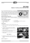
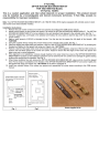
V-Twin Mfg.
Tamer Style Clutch Retainer Kit
Fits 4-Speed 1941-84 Big Twins
VT Part No. 18-1112
This is a custom application rider safety depends on proper installation. This product should only be installed by a
knowledgeable and trained motorcycle technician. V-Twin Mfg. accepts no responsibility for improper installation.
Installation Instructions:
1. Remove all accessories or pipes covering outer primary cover.
2. Remove clutch pressure plate and clutch plates as shown in service manual.
3. If necessary, clean and inspect clutch plates for glazing or oil-soaked plates. Adjust primary chain for proper tension.
4. Remove plates from clutch shell, remove the (3) hold-down springs and discard springs.
5. Remove left hand threaded center nut and discard locking washer.
6. Add shims to gain clearance necessary for proper functioning.
7. Install retainer in clutch shell over ten pins and without shims. Clearance must he between .010" and .015". Add or subtract shims from back or
front to achieve proper clearance (See fig. C). Measure from lip of aluminum spool to flat of aluminum plate.
8. Install nut. Use a couple drops of Loctite on threads if desired.
9. If retainer is to be installed in a KARATA belt drive, DO NOT use steel plate before installing clutch plates. DO use steel plate when installing on
conventional chain drive or Harley belt drive. (Super Max. Primo. or Phase 3) before installing clutch plates.
10. Re-install clutch plates and drivers into clutch shell.
11. Adjust pressure plate spring length to 1·1/32" to 1·1/8". Measure from lip or top plate to flat or bottom plate. Adjust push rod screw to remove play
from throwout bearing and remove slack from cable with cable adjusting screw. Allow approximately 1/4" - 1/8" free play at clutch lever.
12. Reinstall primary and accessories and test drive. There should be no pull when motorcycle is in gear. If pull persists, pressure plate spring is too
light. clutch is out of adjustment, or retainer is installed too tightly. When installed correctly, clutch hub should turn freely with clutch disengaged.
Exploded Side view:
A. Aluminum spool
B. Aluminum backing plate
C. Nylatron plate.
D. Add shims here if to loose
E. Add shims here if to tightening
F. Shaft
Figure C
c
B
E
A
F
D
1. Push rod adjusting screw lock nut
2. Adjuster screw
3. Spring tension adjusting nut (3)
4. Spring collar
5. Springs (10)
6. Outer disc (pressure plate)
7. Spring disc (1967 & earlier)
8. Steel disc (1967 & earlier (3) (1968 & later (4)
9. Friction disc (1967 & earlier (3) (1966 & later (5)
10.Clutch shell
11. Clutch hub nut
*12. Hub nut lock washer
13. Push rod cork oil seal (1964 & earlier)
14. Clutch Hub
15. Clutch hub key
*16. Bearing plate spring (3)
17. Bearing plate
18. Bearing retainer
19. Hub nut seal parts (1964 & earlier)
19A. Hub nut seal (1965 & earlier)
Old Clutch Assembly
Clutch Hub and thrust ring retain installation
Figure A
1 Push rod adjusting screw nut
2. Adjusting screw
3. Spring tension adjusting nut (3)
4. Spring collar
5. Springs (10)
6 Outer disc (pressure plate)
7. Spring disc (1967 s earlier)
8. Steel disc (1967 & earlier (3)) (1968 & later (4)
9. Friction disc (1967 & earlier (3) (1968 & later (5)
10. Clutch hub nut
11.
11A.
12.
13.
14.
15.
16.
17.
18.
19.
Hub nut seal parts (1964 & earlier)
Hub nut seal (1965 & later)
Clutch retainer hub
Thrust rings (2)
Clutch shell
Push rod cork oil seal (1964 & earlier)
Clutch hub
Clutch hub key
Bearing
Bearing retainer
Figure B
New hub and retainer installation
14
10
7
11
11A
13
12
5
4
19
3
2
10 18
1
11A
6
9
11
8
17
15
Note: Figure following name of part indicates quantity necessary for one complete assembly.
Note: Parts numbered *12 and *16 in figure (A) are eliminated in figure (B).
16