1
OC254---1.qxp
2/19/01 11:15 AM
Page 1
2001
SPLIT-TYPE, HEAT PUMP AIR CONDITIONERS
No. OC254
TECHNICAL & SERVICE MANUAL
Series PKFY Wall Mounted
Indoor unit
[Model names]
R407C
R22
[Service Ref.]
PKFY-P20VAM-A
PKFY-P25VAM-A
PKFY-P20VAM-A
PKFY-P25VAM-A
CONTENTS
INDOOR UNIT
1. SAFETY PRECAUTION ·····················3
2. PART NAMES AND FUNCTIONS······5
3. SPECIFICATION·································7
4. OUTLINES AND DIMENSIONS ·········9
5. WIRING DIAGRAM···························10
6. REFRIGERANT SYSTEM DIAGRAM···11
7. TROUBLESHOOTING······················12
8. DISASSEMBLY PROCEDURE·········17
9. PARTS LIST ·····································20
OC254---1.qxp
2/19/01 11:15 AM
Page 2
OC254---1.qxp
1
2/19/01 11:15 AM
Page 3
SAFETY PRECAUTION
Cautions for using with the outdoor unit which adopts R407C refrigerant.
· Do not use the existing refrigerant piping.
-The old refrigerant and lubricant in the existing piping contains a large amount of chlorine which may cause the lubricant
deterioration of the new unit.
· Use “low residual oil piping”.
-If there is a large amount of residual oil (hydraulic oil, etc.) inside the piping and joints, deterioration of the lubricant will result.
· Store the piping to be used during installation indoors with keep both ends sealed until just before brazing.
(Store elbows and other joints in a plastic bag.)
-If dust, dirt, or water enters the refrigerant cycle, deterioration of the oil and compressor trouble may result.
· Use ESTR , ETHER or HAB as the lubricant to coat flares and flange connection parts.
Use liquid refrigerant to seal the system.
-If gas refrigerant is used to seal the system, the composition of the refrigerant in the cylinder will change and performance
may drop.
· Do not use a refrigerant other than R407C.
-If another refrigerant (R22, etc.) is used, the chlorine in the refrigerant may cause the lubricant deterioration.
· Use a vacuum pump with a reverse flow check valve.
-The vacuum pump oil may flow back into the refrigerant cycle and cause the lubricant deterioration.
3
OC254---1.qxp
2/19/01 11:15 AM
Page 4
[1] Service tools
Use the below service tools as exclusive tools for R407C refrigerant.
No.
1
Tool name
Specifications
Gauge manifold
·Only for R407C.
·Use the existing fitting SPECIFICATIONS. (UNF7/16)
·Use high-tension side pressure of 3.43MPa·G or over.
2
Charge hose
3
Electronic scale
4
Gas leak detector
·Use the detector for R134a or R407C.
5
Adapter for reverse flow check.
·Attach on vacuum pump.
6
Refrigerant charge base.
7
Refrigerant cylinder.
·Only for R407C.
·Use pressure performance of 5.10MPa·G or over.
·For R407C
·Top of cylinder (Brown)
·Cylinder with syphon
8
Refrigerant recovery equipment.
[2] Notice on repair service
·After recovering the all refrigerant in the unit, proceed to working.
·Do not release refrigerant in the air.
·After completing the repair service, recharge the cycle with the specified amount of
liquid refrigerant.
[3] Refrigerant recharging
(1) Refrigerant recharging process
1Direct charging from the cylinder.
·R407C cylinder are available on the market has a syphon pipe.
·Leave the syphon pipe cylinder standing and recharge it.
(By liquid refrigerant)
Unit
Gravimeter
(2) Recharge in refrigerant leakage case
·After recovering the all refrigerant in the unit, proceed to working.
·Do not release the refrigerant in the air.
·After completing the repair service, recharge the cycle with the specified amount of
liquid refrigerant.
4
OC254---1.qxp
2/19/01 11:15 AM
2
Page 5
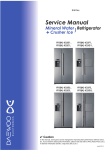
PART NAMES AND FUNCTIONS
● Indoor Unit
PKFY-P20VAM-A
PKFY-P25VAM-A
Air intake
Air intake grille
Filter
Auto Vane
Guide vane
Air Outlet
● MA remote controller [PAR-20MAA]
● Once the operation of the unit is set, subsequent operations can only be performed by pressing the ON/OFF button
repeatedly.
● Operation buttons
TEMP. ADJUSTMENT button
This sets the room temperature. The
temperature setting can be performed
in 1: units
Setting range
Cooler 19: to 30:
Heater 17: to 28:
TIME SETTING button
AIR SPEED button
This sets the current time, start time
and stop time.
This sets the ventilation fan speed.
ON/OFF button
This switches between the operation
and stop modes each time it is pressed.
The lamp on this button lights during
operation.
TIMER button
CENTRALLY CONTROLLED
ON
This switches between continuous
operation and the timer operation.
1Hr.
OFF
˚C
CLOCK
CHECK
˚C
STAND BY
DEFROST
ERROR CODE
TEMP.
NOT AVAILABLE
FILTER
CHECK MODE
TEST RUN
FUNCTION
ON/OFF
AIR DIRECTION button
This adjusts the vertical angle of the
ventilation.
FILTER
OPERATION SWITCH button
Press this button to switch the cooler,
electronic dry (dehumidify), automatic
and heater modes.
CHECK TEST
PAR-20MAA
TIMER SET
FILTER button
This resets the filter service indication
display
LOUVER button
CHECK-TEST RUN button
This switch the horizontal fan motion
ON and OFF.
Only press this button to perform an
inspection check or test operation.
Do not use it for normal operation.
(Not available for this model.)
5
OC254---1.qxp
2/19/01 11:15 AM
Page 6
● Display
CENTRALLY
CONTROLLED display
This indicates when the unit is controlled by optional features such as
central control type remote
controller.
In this display example on the bottom left, a condition where all display lamps light is shown for explanation purposes although this differs
from actual operation.
CLOCK display
The current time , start time and stop
time can be displayed in ten second
intervals by pressing the time switch
button. The start time or stop time is
always displayed during the timer
operation.
AIR DIRECTION display
TIMER display
This displays the air direction.
This indicates when the continuous
operation and time operation modes
are set.
It also display the time for the timer
operation at the same time as when
it is set.
AIR SPEED display
The selected fan speed is displayed.
ROOM TEMPERATURE
1Hr.
CENTRALLY CONTROLLED
OPERATION MODE display
This indicates the operation mode.
ON
OFF
˚C
CLOCK
CHECK
˚C
STAND BY
DEFROST
ERROR CODE
NOT AVAILABLE
TEMP.
FILTER
CHECK MODE
TEST RUN
FUNCTION
ON/OFF
display
The temperature of the suction air
is displayed during operation. The
display range is 8°C to 39°C. The
display flashes 8°C when the actual
temperature is less than 8°C and
flashes 39°C when the actual temperature is greater than 39°C.
FILTER
STANDBY display
The [STANDBY] symbol is only displayed from the time the heating
operation starts unit the heated air
begins to blow.
CHECK TEST
PAR-20MAA
TIMER SET
Operation lamp
This lamp lights during operation,
goes off when the unit stops and
flashes when a malfunction occurs.
CHECK MODE
TEST RUN
DEFROST display
display
This display lights in the check
mode or when a test operation is
performed.
This indicates when the defrost
operation is performed.
FILTER display
This lamp lights when the filter need
to be cleaned.
CHECK display
This indicates when a malfunction
has occurred in the unit which should
be checked.
SET TEMPERATURE display
POWER display
This displays the selected setting
temperature.
This lamp lights when electricity is
supplied to the unit.
Caution
● Only the Power display lights when the unit is stopped and power supplied to the unit.
● When the central control remote control unit, which is sold separately, is used the ON-OFF button, operation switch button
and
TEMP. adjustment button do not operate.
● “NOT AVAILABLE” is displayed when the Air speed button are pressed.This indicates that this room unit is not equipped
with the fan direction adjustment function and the louver function.
● When power is turned ON for the first time, it is normal that “H0” is displayed on the room temperature indication (For max.
2minutes). Please wait until this “H0” indication disappear then start the operation.
6
OC254---1.qxp
2/19/01 11:15 AM
3
Page 7
SPECIFICATION
3-1. Specification
Item
Unit
[,V,Hz
Power
PKFY-P20VAM-A
PKFY-P25VAM-A
Single phase, 220-230-240V, 50Hz
Single phase, 220V, 60Hz
Cooling capacity
kW
2.2
2.8
Heating capacity
kW
2.5
3.2
kW
0.04
Heating
kW
0.04
Cooling
A
0.20
Heating
A
0.20
—
Plastic munsell : <2.60Y 8.66/0.69>
Height
mm
295
Width
mm
815
Depth
mm
158
—
Cross fin
Fan ✕ No.
—
Lineflow fan ✕ 1
Air flow w 2
K/min
5.9-5.6-5.2-4.9
External static pressure
Pa
0
Fan motor output
kW
0.017
Insulator
—
Polyethylene sheet
Air filter
—
PP honey comb
Electric
characteristic
Cooling
Power Supply
Starting Current
Exterior <munsell symbol>
Out dimensions
Heat exchanger
Fan
Pipe dimensions
Gas side [mm(in.)
12.7 (1/2")
Liquid side [mm(in.)
6.35 (1/4")
[mm
PVC pipe VP-16 connectable (I.D. 16)
Noise level w 2
dB
36-35-33-32
Product weight
kg
8.5
Unit drain pipe size
Note 1. Rating conditions
Cooling : Indoor
Outdoor
Heating : Indoor
Outdoor
D.B.
D.B.
D.B.
D.B.
27°C
35°C
20°C
7°C
W.B. 19.0°C
W.B. 24°C
W.B. 6°C
w 2. Air flow and the noise level are indicated as High-Middium 1-Middium2-Low.
7
OC254---1.qxp
2/19/01 11:15 AM
Page 8
3-2. Electrical parts specifications
Model
Symbol
PKFY-P20VAM-A
PKFY-P25VAM-A
Parts name
Room temperature
thermistor
TH21
Resistance 0:/15k", 10:/9.6k", 20:/6.3k", 25:/5.2k", 30:/4.3k", 40:/3.0k"
Liquid pipe thermistor
TH22
Resistance 0:/15k", 10:/9.6k", 20:/6.3k", 25:/5.2k", 30:/4.3k", 40:/3.0k"
Gas pipe thermistor
TH23
Resistance 0:/15k", 10:/9.6k", 20:/6.3k", 25:/5.2k", 30:/4.3k", 40:/3.0k"
Fuse
(Indoor controller board)
FUSE
250V 6.3A
Fan motor
(with thermal fuse)
MF
4-Pole Output 17W / RC4V17
Fan motor capacitor
C1
1.5µF ✕ 440V
Vane motor
(with limit switch)
MV
MSFBC20A76 DC12V
Linear expansion valve
LEV
DC12V Stepping motor drive
Port [3.2 (0~2000pulse) EDM-402ME
Power supply terminal
block
TB2
(L, N, ;) 250V 20A
Transmission terminal
block
TB5
(M1, M2) 250V 10A
8
10
24.4
3
5
5
R1
R8
45
295
Knock out hole
for the remote
controller wiring
Knock out hole
for under piping
Knock out hole
for left - hand
side piping
45
16
R8
B
91.5
2.5
10
C
54
R1
2.5
10
R8
34
A
B
146
150
116
110
60
25.5
Air intake dimension
D
Primary
Secondary
D
Air intake
260
190
159
155
120
205
175
170
225
328
328
295
Installation plate
235
3 Address board is protected by
the plastic cover.
For the setting, remark 1-screw
using the screw driver.
Dip switch
Lotary switch(self address)
Lotary switch(part No.)
Terminal block
Address board
A
5
85
0
12- 2.8
10
0
10
100 or more
4- 9
155
180
190
170
175
205
87- 5.1
225
235
120
85
130 or more
35
10
0
27.5
40
53
65
87
113
128
135
125
110
168
pipe hole 65
4-4.5✕37
4-4.5✕40
407.5
Gas pipe
Connection inner dimension [16
Flare connection 1/2F
Liquid pipe Flare connection 1/4F
Drain pipe
Refrigerant
pipe
Note1. For the installation, be sure to leave some space in case there
is fringe at edge of the ceiling.
Note2. Use the M10 or W3/8 bolt for the installation plate.
Note3. Refer for the specification table it below .
Unit transplant parts
Installation space
Knock out hole
260
Position detail of the tapping screw and bats at pipe intake
4-11✕20
Center of gravity hole for installation
8- 4.3
: There is no terminal board for MA remote controller.
: In case of connecting MA remote controller, use the
cable with the connector attached to the indoor unit.
Please connect the cable with the connector with the
lead wire and connector (Relay connector) for the
MA remote controller of indoor controller board.
Terminal block for transmission
Terminal block for power supply
Detail of
address board
Air outlet
dimension
70.3
158
407.5
4-4.5✕35
90
102.5
124
159
133
122.5
97.5
85
72.5
60
47.5
22.5
0
15
Installation plate
80
Air outlet direction
Air outlet
angle
Terminal block for
transmission
Address board
Terminal block for
power supply
13
Detail of Terminal block
Knock out hole for the
remote controller wiring
Knock out hole for
right - hand side piping
450 Gas pipe
520 Liquid pipe
660 Drain pipe length
695 Air outlet dimension
60
247.5 Air intake dimension
13
815
630 Air intake dimension
21.5
Detail of knock out hole (A B C)
50
Air intake dimension
30
45
50
44
783
16
C
45
5
50
2
R1
4
9
17
2.5
37.4
30
20 or more
298
298
4
1 20 or more
2/19/01 11:15 AM
1 54 or more for left
or left back piping
OC254---1.qxp
Page 9
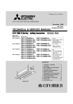
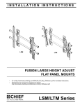
OUTLINES AND DIMENSIONS
PKFY-P20VAM-A
PKFY-P25VAM-A
Unit : mm
R1
5
OC254---1.qxp
2/19/01 11:15 AM
5
Page 10
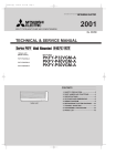
WIRING DIAGRAM
PKFY-P20VAM-A
PKFY-P25VAM-A
Symbol
TH23
Name
Indoor controller board
Remote switch
HA terminal-A
Centrally control
Remote indication
Switch
Capacity code
Mode selection
Thermistor Room temperature,detection
(0:/15T,25:/5.4T)
Pipe temperature,detection/liquid
(0:/15T,25:/5.4T)
CN32
Connector
CN41
CN51
CN52
SW2
SW3
TH21
TH22
Transmission
Circuit board Address board
block
Indoor power board
A.B
ZNR
Varistor
FUSE
Fuse (6.3A)
SW1<A.B> Switch
SW5<A.B>
SW11<A.B>
SW12<A.B>
SW14<A.B>
F.C
Fan phase control
MF
Fan motor
C1
Capacitor(fan motor)
MV
Vane motor
LEV
Linear expansion valve
5
1
2
3
4
5
RED
PNK
BLU
ORN
YLW
Mode selection
Voltage selection
Address setting 1st digit
Address setting 2nd digit
Connection No.
TO OUTDOOR UNIT
TO MA-REMOTE BC CONTROLLER
CONTROLLER
M-NET REMOTE CONTROLLER
DC8.7-13V
DC24-30V
TH23 TH22 TH21
6
Name
Power supply
Terminal
{
BRN
RED
BLU
ORN
YLW
WHT
Symbol
{
LEV
6
5
4
3
2
1
P.B
Name
Thermistor Pipe temperature,detection/Gas TB2
(0:/15T,25:/5.4T) TB5
M1M2
MV
4
(RED)
ADDRESS 3
2
CN43
1
240V
SW1
0
0
3RD 2ND
1ST
DIGIT DIGIT DIGIT
(GRN)
(RED)
LED2
SW2
See fig: w1
(WHT)
SW3
SW12 SW11
8
1 2 3 4 5 6 7 8 910 1 2 3 4
1 2 3 4 5 6 7 8 910
(RED)
ADDRESS 8
7
CN82
6
5
SW14
4
0
3
2
1
CONNECTION
NO.
1 2 3 4 5
1 2 3 4 5
CN51
CN52
1 2 3 4
1 2 3 4 5 6 7 8
CENTRALLY REMOTE
CN42
CN81
INDICATION ADDRESS ADDRESS
CONTROL
0N
0FF
ON
OFF
4
(RED)
FAN 1
1 2
CN2M (GRN)
M-NET
(BLU)
1 3
1 2
CN3A
(BLU)
CN20
INTAKE
(RED)
CND 1 3
(RED)
4 6
1 2 3
CN35P
C1
MICON
BOARD
(BLU)
ZNR
5 CN53P
4 MICON
3 BOARD
2
1 (RED)
CN53M
POWER BOARD 1 2 3 4 5
(RED)
CN35M
POWER BOARD 1 2 3
(BLU)
F.C
LED1
P.B
M.B
Note
1. At servicing for outdoor unit, always follow the wiring diagram of outdoor unit.
2. In case of connecting MA-remote controller, please connect MA remote controller cable in an accessorie
to the connector 1 2 . (Remote controller wire is non-polar.)
3. In case of using M-NET, please connect to TB5.(Transmission line is non-polar.)
: connecter.
4. Symbols used in wiring diagram above are, : terminal block,
5. The setting of the SW2 dip switches differs in the capacity. For the detail,refer to the fig: w1.
6. Please set the switch SW5 according to the power supply voltage.
Set SW5 to 240V side when the power supply is 230 and 240 volts.
When the power supply is 220 volts, set SW5 to 220V side.
LED on indoor board for service
Mark
Meaning
<w1>
Function
Main power supply(Indoor unit:220-230-240V)
power on
lamp is lit
supply for
Power supply for MA-Remote controller
LED2 Power
MA-Remote controller on
lamp is lit
Models
LED1 Main power supply
PKFY-P20VAM
10
SW2
ON
OFF
BLU
RED
1 2
BLK
1 2
RED
1 2 3
BLU
BLU
SW5
220V
1 2 3
CN32 CN34 CN29 CN21
HA REMOTE (GRN) GAS LIQUID
CN41 SWITCH
(BLK) (WHT)
(WHT) (WHT)
ORN
A.B
1 2 3 4
WHT
CN5V
(BLU)
ORN
1 2 3 4 5
CN60
LEV
(WHT)
Models
PKFY-P25VAM
1234
TB2
L
N
PULL
BOX
TB5
1 2
MF
1 2 3 4 5 6
TO NEXT
INDOOR UNIT
GRN/YLW
Legend
Symbol
M.B
SW2
ON
OFF
1234
FUSE
250V
6.3A
FUSE
(15A)
BREAKER
(15A)
POWER SUPPLY
~/N 220-230-240V 50Hz
~/N 220V 60Hz
OC254---1.qxp
6
2/20/01 1:27 PM
Page 11
REFRIGERANT SYSTEM DIAGRAM
PKFY-P20VAM-A
PKFY-P25VAM-A
Gas pipe temperature thermistor
TH23
Gas pipe
Strainer
(#50mesh)
Liquid pipe temperature thermistor
TH22
Liquid pipe
Heat exchanger
Linear expansion
valve
Strainer
(#100mesh)
Room temperature thermistor
TH21
Models
Item
PKFY-P20VAM-A, PKFY-P25VAM-A
Gas pipe
{12.7 (1/2”)
Liquid pipe
{6.35 (1/4”)
11
Flare
OC254---1.qxp
7
2/20/01 10:26 AM
Page 12
TROUBLESHOOTING
7-1. How to check PKFY-P20VAM-A, PKFY-P25VAM-A
Part Name
Check points
Room temperature
thermistor(TH21)
Liquid pipe temperature
thermistor(TH22)
Gas pipe temperature
thermistor(TH23)
Disconnect the connector, then measure the resistance using a tester.
(Surrounding temperature 10°C~30°C)
Vane motor
1Measure the resistance between the terminals using a tester.(Surrounding temperature 25:.)
Normal
4.3k'~9.6k'
M
1-2
Red-Pink
5 Yellow
1 Red
Orange Pink
Connect pin No.
4
1-4
1-5
Red-Orange Red-Yellow
Open or short
1Measure the resistance between the terminals using a tester.(Surrounding temperature 20:.)
FAN
White
Red
Black
1
White-Black
Red-Black
Normal
195'
200'
Abnormal
Open or short
4
6
2Without disassembling the parts, measure the electrical pressure of the gray wire(Signal line) and
brown wire (GND) while the power is on.
Gray Yellow
2
1
CN34
Normal
Abnormal
Linear expansion
valve
CN60
White
Yellow
Orange
LEV
1-3
Red-Blue
Abnormal
400' ± 7%
2
Fan motor
3
(Refer to the next page for a detail.)
Normal
3 Blue
Brown
Abnormal
Open or short
Blue
Red
Brown
1
2
3
4
5
6
!At first, check if the electrical pressure is 12V between the
brown wire(GND) and yellow wire(VCC).
@Slowly start running the fan. It is normal if while the fan rotate once,
the electrical pressure change from 0V to12V then go back to 0V.
If the electrical pressure stay at around 0V or 10V, it means the fan
motor has the defects.
Disconnect the connector then measure the resistance valve using a tester.
(Coil temperature 20°C)
Normal
Abnormal
(1)-(5)
(3)-(5)
(4)-(6)
(2)-(6)
White-Red Yellow-Brown Orange-Red Blue-Brown
Open or short
150' ±10%
12
OC254---1.qxp
2/19/01 11:15 AM
Page 13
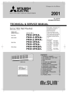
<Thermistor Characteristic graph>
Thermistor for
lower temperature
< Thermistor for lower temperature >
50
Room temperature thermistor(TH21)
Liquid pipe temperature thermistor(TH22)
Gas pipe temperature thermistor(TH23)
40
Rt=15exp { 3480( 1
273+t
0:
10:
20:
25:
30:
40:
Resistance (K")
Thermistor R0=15k' ± 3%
Fixed number of B=3480k' ± 2%
1 )}
273
15k'
9.6k'
6.3k'
5.2k'
4.3k'
3.0k'
30
20
10
0
-20
-10
0
10 20 30
Temperature (:)
40
50
Linear expansion valve
① Operation summary of the linear expansion valve.
• Linear expansion valve open/close through stepping motor after receiving the pulse signal from the indoor controller board.
• Valve position can be changed in proportion to the number of pulse signal.
<Connection between the indoor controller board and the linear expansion valve>
Controller board
DC12V
Brown
6
Red
5
[4
Blue
4
[4
[3
Orange
3
[3
[2
Yellow
2
[2
[1
White
1
[1
Linear expansion valve
4
M
6
5
2
1
White Red
3
Orange
Blue
Brown
Yellow
Drive circuit
Connector(CN60)
Note : Since the number of the connector at the controller board side and the relay connector are different, follow the color of
the lead wire.
13
OC254---1.qxp
2/20/01 10:34 AM
Page 14
<Output pulse signal and the valve operation>
Output
Output
(Phase)
1
2
3
4
{1
ON
OFF
OFF
ON
{2
ON
ON
OFF
OFF
{3
OFF
ON
ON
OFF
{4
OFF
OFF
ON
ON
Closing a valve : 1 → 2 → 3 → 4 → 1
Opening a valve : 4 → 3 → 2 → 1 → 4
The output pulse shift in above order.
❈ 1. When linear expansion valve operation stops, all output phase
become OFF.
2. At phase interruption or when phase does not shift in order,
motor does not rotate smoothly and motor lock, and vibrates.
➁ Linear expansion valve operation
C
D
Valve position (capacity)
❈ When the switch is turned on, 2200 pulse closing valve signal
will be send till it goes to A point in order to define the valve
position.
When the valve move smoothly, there is no noise or vibration
occurring from the linear expansion valve ; however, when the
pulse number moves from E to A or when the valve is locked,
more noise can be heard than normal situation.
❈ Noise can be detected by placing the ear against the screw driver handle while putting the screw driver to the linear expansion
valve.
Close
Open
2000 pulse
Opening a valve
all the way
A
E
Pulse number
B
Extra tightning (80~100pulse)
➂ Trouble shooting
Symptom
Countermeasures
Check points
Operation circuit fail- Disconnect the connector on the controller board, then conure of the micro
nect LED for checking.
6
processor.
5
4
3
2
1
1k’ LED
Exchange the indoor controller board at drive circuit
failure.
Pulse signal will be sent out for 10 seconds as soon as the
main switch is turn on. If there is LED with lights on or lights
off, it means the operation circuit is abnormal.
Linear expansion
valve mechanism is
locked.
Motor will idle and make ticking noise when motor is operated Exchange the linear
while the linear expansion valve is locked. This ticking sound expansion valve.
is the sign of the abnormality.
Short or breakage of Measure the resistance between the each coil (red-white,
the motor coil of the red-orange, brown-yellow, brown-blue) using a tester. It is
linear expansion
normal if the resistance is in the range of 150'+10%.
valve.
Exchange the linear
expansion valve.
Valve doesn't close To check the linear expansion valve, operate the indoor unit If large amount of thermiscompletely (thermis- in fan mode and at the same time operate other indoor units tor is leaked, exchange the
linear expansion valve.
tor leaking).
in cooling mode, then check the pipe temperature <liquid
pipe temperature> of the indoor unit by the
outdoor multi controller board operation
monitor. During fan operation, linear
expansion valve is closed completely and if
Thermistor there are some leaking, detecting temperature of the thermistor will go lower. If the
Linear
expansion
detected temperature is much lower than
valve
the temperature indicated in the remote
controller, it means the valve is not closed all the way. It is
not necessary to exchange the linear expansion valve, if the
leakage is small and not making any trouble.
Wrong connection of Check the color of lead wire and missing terminal of the con- Disconnect the connector
at the controller board,
the connector or
nector.
then check the continuity.
contact failure.
14
OC254---1.qxp
2/19/01 11:15 AM
Page 15
7-2. FUNCTION OF DIP SWITCH
PKFY-P20VAM-A, PKFY-P25VAM-A
Switch Pole
Operation by switch
Function
ON
1
Thermistor<Intake temperature>
position
Built-in remote controller
Indoor unit
2
Filter clogging
Provide
Not provide
3
Filter sign indication
2,500 hr
100 hr
4
Air intake (Note 2)
Not effective
Not effective
Remote indication switching
Thermostat ON signal indication Fan output indication
Humidifier control
Fan operation at Heating mode
SW1
5
Mode
selection 6
7
Address board
<At delivery>
ON
OFF
1 2 3 4 5 6 7 8 9 10
(Note 1) SW1-7=OFF, SW1-8=ON
→Setting air flow.
SW1-7=OFF, SW1-8=ON
→Indoor fan stop.
Heat thermostat ON is operating
Extra low (Note 1)
8
Air flow at heat thermostat Low (Note 1)
OFF
Setting air flow (Note 1)
9
Auto restart function
Effective
Not effective
Power ON/OFF
Effective
Not effective
10
Remarks
OFF
(Note 2) It is impossible to intake
the fresh air.
Reset to SW1-7
Indoor controller board
Set while the unit is off.
MODEL
SW2
Capacity
1~4
code
switch
PKFY-P20VAM-A
SW2
<At delivery>
ON
OFF
Set for each capacity.
1 2 3 4
PKFY-P25VAM-A
ON
OFF
1 2 3 4
1
Heat pump/Cool only
Cooling only
Heat pump
2
Capacity save
Available
Not available
3
Vane
Available
Not available
SW3 4
Function 5
selection 6
Reading change of LEV opening
on reversion of after defrosting
Not available
Available
Vane horizontal angle
Second setting
First setting
Indoor controller board
Set while the unit is off.
<At delivery>
ON
OFF
1 2 3 4 5 6 7 8 9 10
Vane cooling limit angle setting (Note 1) Horizontal angle
Down B,C
7
Indoor linear expansion
valve opening
Effective
Not effective
8
Heater 4 degreed up
Not effective
Effective
9
Target Superheat setting temperature 9 degreed
6 degreed
10
Target Subcool setting temperature 15 degreed
10 degreed
15
(Note 1) At cooling mode, each
angle can be used only 1
hour.
2/19/01 11:15 AM
Page 16
Switch
Remarks
90 1
78
SW11
90 1
23
45 6
45 6
1
SW12
23
10
remote controller is being used.
78
78
90 1
78
SW11
90 1
Address can be set while the
unit is stopped.
Address setting should be done when M-NET
<At delivery>
45 6
SW12
23
Rotary switch
Address board
23
SW11
1st digit
address
setting
SW12
2nd digit
address
setting
Operation by switch
45 6
OC254---1.qxp
45 6
CDE
AB
F01
<At delivery>
SW14
F01
23
This is the switch to be used when the indoor
unit is operated with R2 series outdoor unit
as a set.
45 6
CDE
AB
SW14
23
789
789
SW14
Connection
No.
Setting
Rotary switch
Address board
Address board
SW5
Voltage 2
selection
220V
240V
If the unit is used at the 230V or 240V area,
set the voltage to 240V.
If the unit is used at the 220V, set the voltage
to 220V.
16
<At delivery>
220V
240V
OC254---1.qxp
2/20/01 10:59 AM
8
Page 17
DISASSEMBLY PROCEDURE
PKFY-P25VAM-A
Be careful on removing heavy parts.
PHOTOS & ILLUSTRATIONS
OPERATION PROCEDURE
1. REMOVING THE LOWER SIDE OF THE INDOOR UNIT FROM
THE INSTALLATION PLATE
Figure 1
Figure 2
When there is removing plate
(1) Remove the corner box at right lower side of the indoor
unit.
(2) Insert the removing plate at the back side of the corner box
to remove the indoor unit.
(3) Remove the hook by pulling the lower side of the indoor unit
down as shown in the figure 1.
When there is no removing plate or it can not be used for some
reason.
(1) Remove the front panel.
(2) Insert the screw driver to the corner hole at both left and
right side as shown in the figure 2.
(3) Push it up then, pull down the lower side of indoor unit and
remove the hook.
Push
Corner hole
Indoor unit
removing plate
1
2
Insert
the edge
Pull
Be careful
not to damage
the airflow
adjustment
plate with the
screw driver. Push
2. REMOVING THE FRONT PANEL
Photo 1
❈ Before removing the front panel, leave the open space at
upper side of air flow adjustment plate approximately 2 to 3
cm.
(1) Remove the screw caps then remove the set screws.
(Refer to the photo 1)
(2) Remove the left side of the front panel, then right side.
(3) After removing the lower side of the front panel a little,
remove it as pulling the upper side toward you.
❈ Please pay attention to the nozzle assemble.
Front panel
Set screws
INSTALLING THE FRONT PANEL
(1) Insert the lower side of the front panel under the air
adjustment plate.
(2) Set the upper side of the front panel.
(3) Set the lower side of the front panel then fix it with the
screws.
(4) Press the area indicated as arrow sign and set it to the air
conditioner unit.
2
Figure 3
4 Push
13
Airflow adjustment plate
17
Down
OC254---1.qxp
2/20/01 11:06 AM
Page 18
OPERATION PROCEDURE
PHOTOS & ILLUSTRATIONS
3. REMOVING THE INDOOR MICRO CONTROLLER BOARD
AND INDOOR POWER BOARD
Photo 2
Electrical box cover
(1) Remove the front panel. (Refer to 2)
(2) Remove the electrical box cover (screw 4 ✕ 10).
(Refer to the photo 2)
INDOOR MICRO CONTROLLER BOARD
(1) Disconnect the following connectors on the indoor micro
controller board.
(connector in front of)
● CN60, CN5V, CN34, CN29, CN21
● CN42, CN81, CN3A, CN20
(2) Pull out the indoor micro controller board toward you, then
disconnect the rest of connectors.
● CN53M, CN35M (See the photo 3)
INDOOR POWER BOARD
(1) Disconnect the following connectors on the indoor power
board.
● FAN, CN53P, CN35P, CN2M, CND
(2) Remove the screws of the indoor power board, then pull out
the indoor power board toward you. (See the photo 3)
Screw cap
Electrical box
Photo 3
Indoor micro controller board
Indoor power
board
Indoor power
board
Electrical box
4. REMOVING THE ELECTRICAL BOX
Photo 4
Indoor micro
controller board
(1) Remove the front panel. (Refer to 2)
(2) Remove the electrical box cover.
(3) Pull the nozzle assembly toward you as opening the catch
of the nozzle assembly.
(4) Disconnect the indoor/outdoor connector.
(5) Disconnect the following connector on the indoor micro
controller board. (See the photo 4)
● CN60, CN5V, CN34, CN29, CN21, CN20, CN3A
(6) Disconnect the following connector on the indoor power
board. (See the photo 4)
● FAN, CN2M, CND
(7) Disconnect the ground wire.
(8) Pull the disconnected lead wire out from the electrical box.
(9) Push up the upper fixture catch to remove the box, then
pull the lower fixture and remove it from the box fixture.
Indoor power
board
fixture (lower)
Ground wire set screw
18
fixture (upper)
Electrical box
OC254---1.qxp
2/20/01 11:13 AM
Page 19
OPERATION PROCEDURE
PHOTOS & ILLUSTRATIONS
5. REMOVING THE NOZZLE ASSEMBLY
Photo 5
(1) Remove the front panel (Refer to 2).
(2) Remove the electrical box cover.
(3) Disconnect the connector (CN5V) on the indoor micro con
troller board.
(4) After unhook the right side of the corner box, press the
upper left side and remove the corner box.
(5) Remove the nozzle assemble from the fixture.
(See the photo 5)
(6) Remove the drain hose.
Heat exchanger
Drain hose
Nozzle assembly
fixture
6. REMOVING THE LINE FLOW FAN AND THE FAN MOTOR
fixture
Heat exchanger
Photo 6
(1)
(2)
(3)
(4)
(5)
(6)
(7)
(8)
Remove the front panel. (Refer to 2)
Remove the nozzle assembly. (Refer to 5)
Remove the electrical parts box.
Remove the fixture while pressing the right side of motor
fixture catch. (See the photo 6)
Remove the left side of the motor fixture.
Loosen the screw which fixes the line flow fan to the fan
motor, then remove the fan motor by sliding it to the right
side. (See the photo 6)
Pull the left-hand side of the heat exchanger toward you.
(See the photo 7)
Remove the line flow fan.
Electrical box
Drain hose
Fan motor
fixture (right)
fixture (left)
Line flow fan
fixture set screws
set screws
Drain hose
Nozzle assembly
Photo 7
Heat exchanger
Heat exchanger
fixture (left)
7. REMOVING THE VANE MOTOR
Photo 8
(1) Remove the front panel.
(2) Remove the screw of the electrical parts box cover, and
remove the cover.
(3) Remove the screw of the vane motor, and remove the motor
from the shaft.
(4) Disconnect the vane motor connector (CN5V) on the indoor
controller board.
Heat exchanger
Vane motor
Vane motor connect
screws
Nozzle assembly
8. REMOVING THE LIQUID PIPE THERMISTOR AND GAS
PIPE THERMISTOR
Remove the front panel. (Refer to 2)
Remove the electrical box cover.
Remove the pipe cover.
Cut the wiring fixed band.
Remove the liquid pipe thermistor and gas pipe thermistor.
(See the photo 9)
(6) Disconnect the connector (CN29) (CN21) on the indoor
micro controller board.
Photo 9
Heat exchanger
Gas pipe thermistor
(1)
(2)
(3)
(4)
(5)
19
Liquid pipe thermistor
Electrical box
OC254---1.qxp
9
2/19/01 11:15 AM
Page 20
PARTS LIST
PANEL PARTS
PKFY-P20VAM-A
PKFY-P25VAM-A
Part number that is circled is not shown in the figure.
Q'ty / set
No.
Parts No.
Parts Name
Specifications PKFY-P20VAM-A
PKFY-P25VAM-A
Remarks
(Drawing No.)
1 R01 22A 635 BOX
1
2 R01 22A 651 FRONT PANEL
1
3 R01 22A 500 AIR FILTER
1
4 R01 22A 691 INTAKE GRILLE
1
5 R01 22A 096 SCREW CAP
1
3PCS/SET
1
(DT25C174H03)
6
—
RECEVING COVER
7 R01 22A 054 GRILLE CATCH
1
8 T7W A00 658 CORNER BOX
1
9 R01 22A 808 BACK PLATE
1
10
—
BRAND LABEL
1
20
(BC79R798H02)
Price
Wiring RecomDiagram mended Unit Amount
Symbol Q'ty
OC254---1.qxp
2/19/01 11:15 AM
Page 21
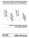
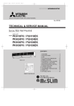
ELECTRICAL PARTS
PKFY-P20VAM-A, PKFY-P25VAM-A
23
22
21
17
20
19
18
17 16 15 14
24
1
1Hr.
CENTRALLY CONTROLLED
ON
OFF
˚C
CLOCK
CHECK
˚C
STAND BY
DEFROST
ERROR CODE
NOT AVAILABLE
TEMP.
FILTER
CHECK MODE
TEST RUN
FUNCTION
ON/OFF
FILTER
CHECK TEST
PAR-20MAA
TIMER SET
2
12 13
3
4
5
6
7
8
9
10
11
Q'ty / set
No.
Parts No.
Parts Name
Specifications PKFY- PKFYP20VAM-A P25VAM-A
Remarks
(Drawing No.)
Wiring RecomDiagram mended
Symbol Q'ty
1 T7W B00 675 FAN GUARD
1
1
2 R01 22A 530 NOZZLE
1
1
3 R01 22A 223 VANE MOTOR
1
1
4 R01 22A 002 AUTO VANE
1
1
1
1
1
1
1
1
1
1
FUSE
1
1
TH21
1
1
A.B
1
1
1
1
TB2
1
1
TB5
1
1
1
1
P.B
M.B
5 R01 22A 527 DRAIN HOSE
6 R01 22A 126 MOTOR BAND
SET (LEFT, RIGHT)
7 R01 07Y 092 VANE SLEEVE
8 T7W 520 239 FUSE
250V 6.3A
9 T7W E12 202 ROOM TEMPERATURE THERMISTOR
10 T7W B01 294 ADDRESS BOARD
11 T7W E00 304 ADDRESS CABLE
12 T7W 512 716 TERMINAL BLOCK
3P (L, N, ;)
13 T7W E05 716 TERMINAL BLOCK
2P (M1, M2)
14
—
ELECTRICAL BOX
15 T7W E03 313 POWER BOARD
MV
(BG00J285G16)
16 R01 E27 310 INDOOR CONTROLLER BOARD
1
1
17 R01 22A 105 RUBBER MOUNT
2
2
18 R01 E38 202 PIPE TEMPERATURE THERMISTOR GAS
1
1
TH23
19 T7W E06 202 PIPE TEMPERATURE THERMISTOR LIQUID
1
1
TH22
20 T7W E11 762 FAN MOTOR
1
1
MF
21 R01 22A 114 LINE FLOW FAN
1
1
22 R01 005 103 SLEEVE BEARING
1
1
23 R01 22A 102 BEARING MOUNT
1
1
1
1
24
—
REMOTE CONTROLLER
RC4V17-AA
PAR-20MAA
21
R.B
Price
Unit
Amount
OC254---1.qxp
2/19/01 11:15 AM
Page 22
HEAT EXCHANGER PARTS
PKFY-P20VAM-A
PKFY-P25VAM-A
1
2
Q'ty / set
No.
1
Parts No.
Parts Name
Specifications PKFY- PKFYP20VAM-A P25VAM-A
T7W E83 480 HEAT EXCHANGER
With connection pipe
T7W E84 480 HEAT EXCHANGER
With connection pipe
2 R01 E27 401 LINEAR EXPANSION VALVE
Remarks
(Drawing No.)
Price
Wiring RecomDiagram mended Unit Amount
Symbol Q'ty
1
1
1
22
1
LEV
OC254---1.qxp
2/19/01 11:15 AM
Page 23
OC254---1.qxp
2/19/01 11:15 AM
Page 24
HEAD OFFICE : MITSUBISHI DENKI BLDG., 2-2-3, MARUNOUCHI, CHIYODA-KU TOKYO 100-8310, JAPAN
cCopyright 2001 MITSUBISHI ELECTRIC ENGINEERING CO., LTD.
Distributed in Feb. 2001. No. OC254 785
Made in Japan
New publication, effective Feb. 2001
Specifications subject to change without notice