1
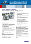
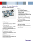
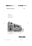
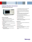
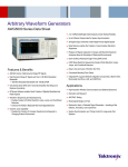
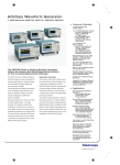
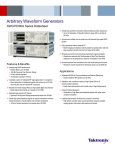
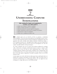
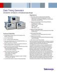
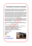
®
Advanced Test Equipment Rentals
E stablished 1981
www.atecorp.com 800-404-ATEC (2832)
Arbitrary Waveform Generator
AWG5000 Series (AWG5014 • AWG5012 • AWG5004 • AWG5002)
Features & Benefits
AWG5000 Series.
The AWG5000 Series of Arbitrary Waveform Generators Delivers
the Industry’s Best Mixed Signal Stimulus Solution for Today’s
Complex Measurement Challenges
The AWG5000 Series of Arbitrary
Waveform Generators delivers the
optimal combination of industry leading
sample rate, vertical resolution, signal
fidelity and waveform memory length,
all in an easy-to-use self-contained
package.
The series offers the industry’s best
solution to the challenging signal stimulus issues faced by designers verifying,
characterizing and debugging sophisticated electronic designs.
Meeting the needs of today’s design
engineers, the series provides excellent
signal dynamic range and integrity.
AWG5000 Series models, with a 14
bits DA converter based sample rate
from 600 MS/s to 1.2 GS/s, two to four
output channels, synchronized four to
eight digital marker outputs, and 28channels of digital data outputs, easily
solve the toughest measurement challenges in wireless base band I/Q
communications, digital consumer
product design such as imaging
devices, data conversion equipment
and semiconductor design and test.
The open Windows (Windows XP)based instruments are easy and
convenient to use and connect easily
with peripherals and third-party software.
1.2 Gs/s and 600 MS/s Models
14 bit Vertical Resolution
2 or 4 Arbitrary Waveform
Differential/Single-ended Outputs
– Up to 4.5 Vp-p Single-ended
and 9 Vp-p at Differential Output
into 50 Ω
– 0.95 ns Tr/Tf (10 to 90%) at
0.6 Vp-p
– +/– 5 ns Range (50 ps
Resolution) Inter Channel
Skew Control
– SFDR: 80 dBc (1 MHz),
64 dBc (10 MHz)
4 or 8 Variable Level Marker
Outputs
– Up to 3.7 Vp-p Single-ended
Output into 50 Ω
– 300 ps Tr/Tf (20 to 80%)
at 0 to 1 V
– Up to 1 ns Range (50 ps
Resolution) Delay Control
28 Bits Ch 1/Ch 2 Variable Level
Digital Data Output
– Up to 3.7 Vp-pSingle-ended
Output into 50 Ω
– 300 ps Tr/Tf (20 to 80%)
at 0 to 1 V
Up to 32 M Point Record Length
For Longer Data Streams
Down to 800 ps Resolution
Edge Timing Shift Control
Real-time Sequencing Creates
Infinite Waveform Loops, Jumps,
and Conditional Branches
Easy to Use and Learn Shortens
Test Time
Intuitive User Interface Based
on Windows 2000 XP
Convenient Bench Top
Form Factor
Integrated PC Supports Network
Integration and Provides a Builtin DVD, Removable Hard Drive,
LAN and USB ports
Applications
Designing, Testing and Deploying
Wireless Communications:
– High Fidelity Quadrature
Modulation I and Q Base-band
Signals (Polar Modulation:
I/Q + Magnitude Control, Two
Pair of I/Q for MIMO)
Imaging
– Stimulus Signals for Imaging
Display and Recording Devices
(CCD, LCD)
Data Conversion
– Stimulus Signals for Data
Conversion Devices (ADC, DAC)
Mixed Signal Design and Test
– 2/4Ch Analog + 4/8Ch Marker
Outputs + 28 Bit Digital Data
Outputs
Real-world, Ideal or Distorted
Signal Generation – Including
All the Glitches, Anomalies and
Impairments
Enhanced/Corrupted Playback
of DSO Captured Signals
Waveform Vectors Imported from
Third-party Tools such as MathCAD,
MATLAB, Excel and Others
Arbitrary Waveform Generator
AWG5000 Series (AWG5014 • AWG5012 • AWG5004 • AWG5002)
Wireless I/Q and IF Signal
Generation
Tektronix AWGs support “Wireless
Everywhere” by enabling the latest
Digital RF technology, increasing wireless network capacity and delivering
the performance that supports higher
modulation bandwidth and modulation
schemes.
The AWG 5000 Series’ 1.2 GS/s,
(600 MS/s), with enough signal
dynamic range and SFDR via 14 bit
vertical resolution meets narrowband IQ
applications to broadband IF applications. The AWG5000 is able to
generate not only analog IQ/IF signals,
but digital data IQ/IF. The MIMO
(Multiple Input Multiple Output) system
that supports W-LAN /Wi-Max using
space-multiplex with multiple antennas
is a leading edge technology for reliable
and faster data rate communication.
The AWG5000 Series generates up to
four analog channels (eight channels via
two instruments) to simultaneously
generate MIMO signals. The series can
generate two pairs of IQ signals (four
pairs with two instruments) as an IQ
generator, and four pairs of IF signals
(eight pairs with two instruments) as an
IF generator. With the two channels
models, ch 1 and ch 2 digital data
output is available as an option.
2
Typical Signal Injection.
EVM/Constellation measurement.
AWG5000 Series • www.tektronix.com/signal_sources
Arbitrary Waveform Generator
AWG5000 Series (AWG5014 • AWG5012 • AWG5004 • AWG5002)
Spurious Performance
The 14 bit vertical resolution and
sophisticated design of the AWG5000
Series provides ample signal dynamic
range and purity. The SFDR performance is 80 dBc for 1 MHz signal and
64 dBc for 10 MHz signal.
Multi-Level Logic Signal
RTSA Spectrum view.
One technique to increase the data rate
without increasing the transition rate is
applying multi-level signals, wherein a
signal can assume more than the standard binary two levels. In multi-level
signaling, one can think of multi-level
discrete amplitudes of a signal. This
phenomenon is known as pulse amplitude-modulation or PAM. A 9PAM
signal, a signal with nine different amplitudes, increases the data rate by four
without increasing the transition rate of
the signal.
The AWG5000 Series enables you to
test your latest design by generating
any kind of mixed or multi-level signal.
Mixed Signal Generation
9-PAM with 250 Mbps.
AWG5012 and AWG5002 models can
generate two analog signals with fourdigital marker outputs, supporting 28
digital outputs (ch 1 and ch 2 data) as
an option. They deliver a mixed analog
and digital signal generator and the most
versatile solution for a broad range of
applications, including consumer electronics such as ADC/DAC converter
and imaging or display devices.
Mixed signal test by TDS/TLA iView.™
AWG5000 Series • www.tektronix.com/signal_sources
3
Arbitrary Waveform Generator
AWG5000 Series (AWG5014 • AWG5012 • AWG5004 • AWG5002)
Additional Software
Application Tools to Extend
Waveform Generation
RFXpress (RFX100)
RFXpress is a software package that
synthesizes digitally modulated base
band IQ and IF signals. It takes IQ and
IF signal generation to the next level
and fully exploits the wideband signal
generation capabilities of Arbitrary
Waveform Generators (AWGs).
Supporting a wide range of modulations, as well as the symbol map functions, the software allows you to define
your own modulation.
RFXpress is a powerful easy-to-use
software package to synthesize IQ and
IF signals for arbitrary waveform generators (AWG). It runs as an integral part
of the AWG5000 series arbitrary waveform generators or from an external
PC.
For more details on RFXpress visit
www.tek.com.
4
AWG5000 Series • www.tektronix.com/signal_sources
Arbitrary Waveform Generator
AWG5000 Series (AWG5014 • AWG5012 • AWG5004 • AWG5002)
Characteristics
AWG5014
AWG5012
AWG5004
AWG5002
Arbitrary Waveforms
Waveform Length
Number of Waveforms
Sequence Length
Sequence Repeat Counter
Sequence Control
Jump Mode
1 to 16,200,000 points (or 1 to 32,400,000 points, option 01)
1 to 16,000
1 to 4,000 steps
1 to 65,536 or infinite
Repeat count, Trigger, Go-to-N and Jump
Synchronous and Asynchronous
Run Modes
Continuous
Triggered
Gated
Sequence
Waveform is iteratively output. If a sequence is defined, the sequence order and repeat functions are applied
Waveform is output only once when an external, internal, GPIB, LAN or manual trigger is received
Waveform begins output when gate is true and resets to beginning when false
Waveform is output as defined by the sequence
Clock Generator
Sampling Frequency
Resolution
Internal Clock
Accuracy
Clock Phase Noise
10 MS/s to 1.2 GS/s
10 MS/s to 600 MS/s
8 digits
Within ± (1 ppm + Aging),
Aging: within ± 1 ppm/year
Less than –90 dBc/Hz at 100 kHz offset
Internal Trigger Generator
Internal Trigger Rate
Range
Resolution
1.0 μs to 10.0 s
3 digits, 0.1 μs minimum
Skew Control Between Outputs
Range
Resolution
– 5 ns to + 5 ns
5 ps
AWG5000 Series • www.tektronix.com/signal_sources
5
Arbitrary Waveform Generator
AWG5000 Series (AWG5014 • AWG5012 • AWG5004 • AWG5002)
AWG5014
AWG5012
AWG5004
AWG5002
4
2
Main Arbitrary Waveform Output
Resolution
14 bits
Analog Output
(in to 50 Ω) (Twice for Hi_Z input)
Number of Arb Outputs
4
2
Output Style
Output Impedance
Connector
Differential
50 Ω
BNC Front
Amplitude
Output Voltage
Amplitude
Resolution
DC Accuracy
Offset (into 50 Ω)
Range
Resolution
Accuracy
Normal: –4.5 V to + 4.5 V,
Direct –0.3 V to +0.3 V
Normal: 20 mVp-p to 4.5 Vp-p,
Direct; 20 mVp-p to 0.6 Vp-p
1 mV
±(2.0% of Amplitude + 2 mV) at offset = 0 V
Normal: –2.25 V to +2.25 V,
Direct: N/A
1 mV
±(2% of offset +10 mV at minimum amplitude
Pulse Response
Rise/Fall time: (10% to 90%).
Normal: 1.4 ns (2.0 Vp-p),
Direct: 0.95 ns (0.6 Vp-p)
Bandwidth (–3dB)
Normal: 250 MHz (2.0 Vp-p),
Direct: 370 MHz (0.6 Vp-p)
Ringing
Normal: 750 mVp-p (4.5 Vp-p filter through), 80 mVp-p (2.0 Vp-p filter through),
Direct: 60 mVp-p (0.6 Vp-p)
Low Pass Filter
High range: 100 MHz, 20 MHz,
Low range: through, 100 MHz, 20 MHz,
Direct: N/A
Delay from Marker
Normal: 17.5 ns to 19.4 ns (20 MHz filter),
3.8 ns to 5.7 ns (100 MHz filter),
0 to 1.9 ns (Through),
Direct: –1.5 ns to 0.4 ns
Sine Wave Characteristics
(1.2 GS/s clock, 32 waveform points, 37.5 MHz signal frequency)
(600 MS/s clock, 32 waveform points, 18.75 MHz signal frequency)
Harmonics
Normal: ≤–40 dBc (2.0 Vp-p),
Direct ≤=–49 dBc (0.6 Vp-p)
Normal: ≤–46 dBc (2.0 Vp-p),
Direct ≤=–55 dBc (0.6 Vp-p)
Non Harmonics
Normal: ≤–60 dBc (2.0 Vp-p, DC to 600 MHz)
Normal: ≤–60 dBc (2.0 Vp-p, DC to 300 MHz)
Phase noise
≤ –85 dBc/Hz (2.0 Vp-p, 10 kHz offset) –85 dBc/Hz (2.0 Vp-p, 10 kHz offset)
SFDR
50 dBc (Normal, 37.5 MHz, 1.2 GS/s, 2.0 Vp-p)
56 dBc (Normal, 18.75 MHz, 600 MS/s, 2.0 Vp-p)
60 dBc (Normal, 10 MHz, 600 MS/s, 1.0 Vp-p)
60 dBc (Normal, 10 MHz, 600 MS/s, 1.0 Vp-p)
80 dBc (Normal, 1 MHz, 600 MS/s, 1.0 Vp-p)
80 dBc (Normal, 1 MHz, 600 MS/s, 1.0 Vp-p)
64 dBc (Direct, 10 MHz, 600 MS/s, 0.6 Vp-p)
64 dBc (Direct, 10 MHz, 600 MS/s, 0.6 Vp-p)
80 dBc (Direct, 1 MHz, 600 MS/s, 0.6 Vp-p)
80 dBc (Direct, 1 MHz, 600 MS/s, 0.6 Vp-p)
6
AWG5000 Series • www.tektronix.com/signal_sources
Arbitrary Waveform Generator
AWG5000 Series (AWG5014 • AWG5012 • AWG5004 • AWG5002)
AWG5014
AWG5012
8 (2 per ch)
4 (2 per ch)
AWG5004
AWG5002
8 (2 per ch)
4 (2 per ch)
Auxiliary Outputs
Marker Output
Number of Outputs
Output Style
Output Impedance
Connector
Single-ended
50 Ω
BNC Front
Level (into 50 Ω)
(Twice for Hi_Z input)
Output Windows
Amplitude
Resolution
DC Accuracy
Maximum Output Current
Rise/Fall Time (20% to 80%)
–1.00 V to + 2.7 V
0.10 Vp-p to 3.7 Vp-p
10 mV
±(10% of setting +120 mV)
± 54 mA /ch
300 ps (1.0 Vp-p, Hi +1.0 V, Lo 0 V)
Skew Adjust Between Markers
Range
Resolution
Random Jitter (Typical)
RMS
Total Jitter (Typical)
Peak to Peak (p-p)
0 to 1000 ps
50 ps
1010 clock pattern
5 psrms
2^15–1 PN data pattern
80 psp-p
Clock (VCO) Out
Range
Amplitude
Impedance:
Connector
600 MHz to 1.2 GHz
0.4 Vp-p into 50 Ω to GND
50 Ω, AC coupling
BNC Rear
10 MHz Reference Out
1.2 Vp-p into 50 Ω. Max 2.5 Vp-p open
50 Ω, AC coupling
BNC Rear
Amplitude
Impedance
Connector
DC Outputs
Number of Outputs
Range
Resolution
Max. Current
Connector
4: independently controlled outputs
–3.0 to +5.0 V
10 mV
± 100 mA
2x4 pin header on front panel
Digital Data Output (Option 03)
Number of Output
Output Style
Output Impedance
Connector
NA
14 bits output on channel 1
and channel 2 (28 total)
Single-ended
50 Ω
SMB rear
NA
14 bits output on channel 1
and channel 2 (28 total)
Single-ended
50 Ω
SMB rear
Level (into 50 Ω)
(Twice for Hi_Z input)
Output Windows
Amplitude
Resolution
DC Accuracy
Maximum Output current
Rise/Fall Time (20% to 80%)
–1.00 V to + 2.7 V
0.10 Vp-p to 3.7 Vp-p
10 mV
± (10% of setting +120 mV)
± 54 mA /ch
300 ps
(1.0 Vp-p, Hi +1.0 V, Lo 0 V)
–1.00 V to + 2.7 V
0.10 Vp-p to 3.7 Vp-p
10 mV
± (10% of setting +120 mV)
± 54 mA /ch
300 ps
(1.0 Vp-p, Hi +1.0 V, Lo 0 V)
AWG5000 Series • www.tektronix.com/signal_sources
7
Arbitrary Waveform Generator
AWG5000 Series (AWG5014 • AWG5012 • AWG5004 • AWG5002)
Auxiliary Inputs
Trigger In
1 kΩ or 50 Ω
POS or NEG
BNC Front
1 kΩ: ±10 V. 50 Ω: ±5 V
Impedance
Polarity
Connector
Input Voltage Range
Threshold
Level
Resolution
Trigger Jitter
–5.0 V to 5.0 V
0.1 V
2.0 ns to 4.5 ns (Typical)
Trigger Mode
Minimum Pulse Width
Trigger Hold-off
Delay to Analog Out
20 ns
832* sampling_period – 100 ns
128* sampling_period + 250 ns
Gate Mode
Minimum Pulse Width
Delay to Analog Out
1024* sampling_period + 10 ns
640* sampling_period + 260 ns
Event Input
1 kΩ or 50 Ω
POS or NEG
BNC Front
1 kΩ: ±10 V. 50 Ω: ±5 V
–5.0 V to 5.0 V
0.1 V
Impedance
Polarity
Connector
Input Voltage Range
Threshold
Resolution
Sequence Mode Mode
Minimum Pulse Width
Event Hold Off
Delay to Analog Out
20 ns
1024* Sampling Period + 10 ns
640* Sampling Period + 280 ns (Jump timing: Asynchronous jump)
External Clock IN
Input Voltage Range
Impedance
Frequency Range
Clock Divider
Connector
0.2 Vp-p to 0.8 Vp-p
50 Ω, AC coupled
600 MHz to 1.2 GHz
1/1, 1/2, 1/4…1/32
1/2, 1/4…1/32
BNC Rear
Reference Clock IN
Input Voltage Range
Impedance
Frequency Range
Connector
0.2 Vp-p to 3.0 Vp-p
50 Ω, AC coupled
10 MHz, 20 MHz, 100 MHz (with ±0.1%)
BNC Rear
Phase Lock IN
Input Ranges
Input Voltage Range
Impedance
Multiple Rate
Connector
Add IN
Impedance
DC Gain
Bandwidth
Input Voltage Range
Connector
8
5 MHz to 600 MHz (acceptable frequency drift is ±0. 5%)
0.2 Vp-p to 3 Vp-p
50 Ω, AC coupled
1 to 240
1 to 120
BNC Rear
For each analog channel
50 Ω, DC coupled
1
DC to 100 MHz at –3 dB
± 1.0 V
BNC Rear
AWG5000 Series • www.tektronix.com/signal_sources
Arbitrary Waveform Generator
AWG5000 Series (AWG5014 • AWG5012 • AWG5004 • AWG5002)
AWG5000 Series Common Features
Waveform File Import Capability
Tektronix TDS5000/6000/7000, DPO4000/7000/70000, DSA70000 (*.wfm). TDS3000 (*.wfm)
AWG400s/500s/610/615/710/710B (*.wfm, *.pat, *.seq), DTG5000s (*.DAT) Text data file
(Third party software creation waveform data: MATLAB, MathCad, Excel)
IVI-com driver and MATLAB library
S/W driver for 3rd party S/W
Instrument Control/Data Transfer Ports
GPIB
Ethernet (10/100/1000Base-T)
Computer System & Peripherals
Remote control and data transfer. (Conforms to IEEE-Std 488.1, compatible with IEEE 488.2 and SCPI-1999.0)
Remote control and data transfer. (Conforms to IEEE 802.3). RJ-45
Windows XP Professional, 512 MB SDRAM, 80 GB removable Hard Drive at rear (available front mount kit),
CD-RW/DVD drive at front, included USB compact keyboard and mouse
USB 2.0 compliant ports (6 total, 2 front, 4 rear), PS/2 mouse and keyboard connectors (rear panel),
RJ-45 Ethernet connector (rear panel) supports 10/100/1000BASE-T, XGA out
10.4 inch, LCD color display with touch screen, 1024 (H)x768 (V) (XGA)
100 to 240 VAC, 47 to 63 Hz
450 W
UL61010-1, CAN/CSA-22.2, No.61010-1-04, EN61010-1, IEC61010-1
EN 55011 (Class A), IEC61000-3-2, IEC61000-3-3
IEC61326, IEC61000-4-2/3/4/5/6/8/11
PC I/O Ports
Display Characteristics
Power Supply
Power Consumption
Safety
Emissions
Immunity
Regional Certifications
Europe
Australia/New Zealand
EN61326
AS/NZS 2064
Physical Characteristics
mm/kg
lbs/in.
Dimension
mm
in.
Height
Width
Length
245
465
500
9.6
18.0
19.7
Weight (approx.)
kg
lbs.
28.5
43.0
62.8
2 cm
15 cm
7.5 cm
0.8 inch
6 inch
3 inch
Net19.5
Net with Package
Mechanical Cooling
Required Clearance
Top and Bottom
Side
Rear
Environmental
Temperature
Humidity
Altitude
Random Vibration
Sine Vibration
Mechanical shock
Operating
Non-operating
+10º C to +40º C
5% to 80% relative humidity (% RH) at up to +30º C,
5% to 45% RH above +30º C up to +50º C
Up to 3,048 meters (10,000 feet)
0.27 GRMS, 5 to 500 Hz, 10 minutes per axis
0.33 mmp-p (0.013 inchp-p) constant displacement, 5 to 55 Hz
Half-sine mechanical shocks, 30 g peak amplitude,
11 msec duration, 3 drops in each direction of each axis
–20º C to +60º C
5% to 90% RH (Relative Humidity) at up to +30º C,
5% to 45% RH above +30º C up to +50º C
Up to 12,192 meters (40,000 feet)
2.28 GRMS, 5 to 500 Hz, 10 minutes per axis
NA
NA
AWG5000 Series • www.tektronix.com/signal_sources
9
Arbitrary Waveform Generator
AWG5000 Series (AWG5014 • AWG5012 • AWG5004 • AWG5002)
Ordering Information
Arbitrary Waveform
Generator Mainframe
AWG5014
1.2 GS/s, 4-channel, 14bits, 16 M point/channel
Arbitrary Waveform Generator.
AWG5012
1.2 GS/s, 2-channel, 14bits, 16 M point/channel
Arbitrary Waveform Generator.
AWG5004
600 MS/s, 4-channel, 14bits, 16 M point/channel
Arbitrary Waveform Generator.
AWG5002
600 MS/s, 2-channel, 14bits, 16 M point/channel
Arbitrary Waveform Generator.
All Models Include:Accessory pouch, front cover,
USB mouse, compact USB key board, lead set for
DC output, stylus for touch screen 2 each,
Windows® XP operating system restore DVD and
instructions, AWG5000 Series product software CD
and instructions, Document CD with Browser, Quick
Start User Manual, registration card, Certificate of
Calibration, power cable.
Note: Please specify power cord and language
option when ordering.
Instrument Options
AWG5014/AWG5012,
AWG5004/AWG5002
Opt. 01 – Waveform Length Expansion (from 16 M
to 32 M).
Common Options
Product Upgrade
AWG5014, AWG50UP
International Power Plugs
Opt. M14 – Waveform Length Expansion
from 16 M point to 32 M point.
Opt. A0 – North America power.
Opt. A1 – Universal EURO power.
Opt. A2 – United Kingdom power.
Opt. A3 – Australia power.
Opt. A5 – Switzerland power.
Opt. A6 – Japan power.
Opt. A10 – China power.
Opt. A99 – No power cord or AC adapter.
Opt. M12 – Waveform Length Expansion
from 16 M point to 32 M point.
Opt. D13 – Digital Data Outputs.
Language Options
Product Upgrade
AWG5004, AWG50UP
Opt. L0 – English.
Opt. L5 – Japanese.
Opt. L7 – Simplified Chinese.
Opt. L8 – Traditional Chinese.
Product Upgrade
AWG5002, AWG50UP
Service
Opt. CA1 – A single calibration event.
Opt. C3 – Calibration service 3 years.
Opt. C5 – Calibration service 5 years.
Opt. D1 – Calibration data report.
Opt. D3 – Calibration data report 3 years (with
option C3).
Opt. D5 – Calibration data report 5 years (with
option C5).
Opt. R3 – Repair service 3 years.
Opt. R5 – Repair service 5 years.
Post-sales Service Options: (e.g., AWG5012-CA1).
CA1 – A single calibration event.
R3DW – Repair service coverage 3 years.
R5DW – Repair service coverage 5 years.
R2PW – Repair service coverage 2 years
post warranty.
R1PW – Repair service coverage 1 year
post warranty.
AWG5012/AWG5002
Opt. 03 – 28 bits digital data outputs (digital data of
ch 1 and ch 2).
10
Product Upgrade
AWG5012, AWG50UP
AWG5000 Series • www.tektronix.com/signal_sources
Opt. M04 – Waveform Length Expansion
from 16 M point to 32 M point.
Opt. M02 – Waveform Length Expansion
from 16 M point to 32 M point.
Opt. D03 – Digital Data Outputs.
Arbitrary Waveform Generator
AWG5000 Series (AWG5014 • AWG5012 • AWG5004 • AWG5002)
Recommended Accessories
Item
Description
Parts Number
150 ps (10% to 90%)
015-0710-00
250 ps (10% to 90%)
015-0711-00
500 ps (10% to 90%)
015-0712-00
1000 ps (10% to 90%)
015-0713-00
2000 ps (10% to 90%)
015-0714-00
SMA Cable
102 cm (40 inch)
012-1690-00
SMB Cable
51 cm (20 inch)
012-1503-00
Rack Mount kit
Rack Mount Kit with instruction
016-1983-00
Front removable HDD kit
016-1979-01
SATA disk assembly (no software installation)
065-0753-00
English
071-2078-00
Transition Time Converter
Pin Header
Front Removable HDD Bay
Replacement Hard Disk
Documentation
Quick Start User Manual
Service Manual
Japanese
071-2079-00
Simplified Chinese
071-2080-00
Traditional Chinese
071-2081-00
English
071-2083-00
Warranty
One-year parts and labor.
AWG5000 Series • www.tektronix.com/signal_sources
11
Contact Tektronix:
Arbitrary Waveform Generator
AWG5000 Series (AWG5014 • AWG5012 • AWG5004 • AWG5002)
ASEAN/Australasia (65) 6356 3900
Austria +41 52 675 3777
Balkans, Israel, South Africa and other ISE Countries +41 52 675 3777
Belgium 07 81 60166
Brazil & South America (11) 40669400
Canada 1 (800) 661-5625
Central East Europe, Ukraine and the Baltics +41 52 675 3777
Central Europe & Greece +41 52 675 3777
Denmark +45 80 88 1401
Finland +41 52 675 3777
France +33 (0) 1 69 86 81 81
Germany +49 (221) 94 77 400
Hong Kong (852) 2585-6688
India (91) 80-22275577
Italy +39 (02) 25086 1
Japan 81 (3) 6714-3010
Luxembourg +44 (0) 1344 392400
Mexico, Central America & Caribbean 52 (55) 5424700
Middle East, Asia and North Africa +41 52 675 3777
The Netherlands 090 02 021797
Norway 800 16098
People’s Republic of China 86 (10) 6235 1230
Poland +41 52 675 3777
Portugal 80 08 12370
Republic of Korea 82 (2) 6917-5000
Russia & CIS +7 (495) 7484900
South Africa +27 11 206 8360
Spain (+34) 901 988 054
Sweden 020 08 80371
Switzerland +41 52 675 3777
Taiwan 886 (2) 2722-9622
United Kingdom & Eire +44 (0) 1344 392400
USA 1 (800) 426-2200
For other areas contact Tektronix, Inc. at: 1 (503) 627-7111
Updated 12 November 2007
For Further Information
Tektronix maintains a comprehensive, constantly expanding collection of
application notes, technical briefs and other resources to help engineers
working on the cutting edge of technology. Please visit www.tektronix.com
Product(s) are manufactured in ISO registered facilities.
Product(s) complies with IEEE Standard 488.1-1987, RS-232-C, and with
Tektronix Standard Codes and Formats.
Copyright © 2008, Tektronix. All rights reserved. Tektronix products are
covered by U.S. and foreign patents, issued and pending. Information
in this publication supersedes that in all previously published material.
Specification and price change privileges reserved. TEKTRONIX and
TEK are registered trademarks of Tektronix, Inc. All other trade names
referenced are the service marks, trademarks or registered trademarks
of their respective companies.
07/08 JS/WOW
76W-20381-3