1
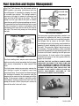
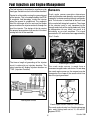
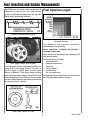
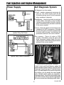
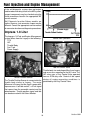
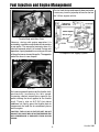
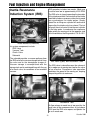
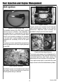
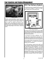
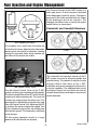
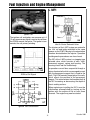
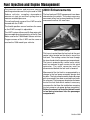
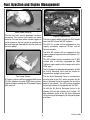
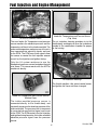
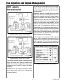
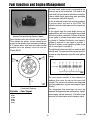
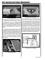
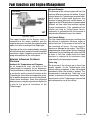
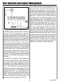
Technicians
Reference
Booklet
Fuel Injection and
Engine Management
Module 406
MSA5P0161C
© Copyright 2001
Subaru of America, Inc.
All rights reserved. This book may not be reproduced
in whole or in part without the express permission of
Subaru of America, Inc.
Subaru of America, Inc. reserves the right at any time
to make changes or modifications to systems,
procedures, descriptions, and illustrations contained
in this book without necessarily updating this
document. Information contained herein is considered
current as of October 2001.
© Subaru of America, Inc. 2001
Fuel Injection and Engine Management
Table of Contents
Slide Sequence ......................................................................................................................................................... 5
Introduction ............................................................................................................................................................. 10
Air Induction System .............................................................................................................................................. 10
Fuel Supply ............................................................................................................................................................. 13
Sensors ................................................................................................................................................................... 15
Fuel Injection Logic ................................................................................................................................................ 16
Learning Control ..................................................................................................................................................... 17
Ignition System Control ......................................................................................................................................... 17
Power Supply .......................................................................................................................................................... 19
Self Diagnosis System ............................................................................................................................................ 19
Impreza 1.8 Liter ..................................................................................................................................................... 20
SVX .......................................................................................................................................................................... 22
Inertia Resonance Induction System (IRIS) ........................................................................................................... 23
SVX Ignition ............................................................................................................................................................ 24
SVX Fuel Delivery System ...................................................................................................................................... 25
Fuel Tank Components ........................................................................................................................................... 26
Fuel Tank Servicing ................................................................................................................................................ 26
Sub Assemblies ................................................................................................................................................ 27
Radiator Fan Control ............................................................................................................................................... 27
Relay Control Circuit ........................................................................................................................................ 28
Motor Control Circuit ........................................................................................................................................ 28
Torque Reduction System ................................................................................................................................ 28
1999 Enhancements ................................................................................................................................................ 28
D MPI ....................................................................................................................................................................... 28
Crankshaft and Camshaft Reluctors ................................................................................................................ 30
L MPI ....................................................................................................................................................................... 31
2000 Enhancements ................................................................................................................................................ 32
2001 Legacy Enhancements ................................................................................................................................... 37
2002 Impreza Enhancements ................................................................................................................................. 42
Turbocharger ........................................................................................................................................................... 44
Turbocharger Testing ............................................................................................................................................. 46
Wastegate Control ............................................................................................................................................ 46
Intercooler ............................................................................................................................................................... 47
External Influences On Boost Pressure .......................................................................................................... 49
Ambient Air Temperature and Pressure ............................................................................................ 49
Exhaust Diameter ............................................................................................................................ 49
Fuel Octane Rating .......................................................................................................................... 49
Turbo Lag ........................................................................................................................................ 49
Service Bulletins ..................................................................................................................................................... 52
406 Module Service Help-Line Updates ................................................................................................................. 53
4
October 2001
5
October 2001
Slide Sequence
Slide No.
1
2
3
4
5
6
7
8
9
10
11
12
13
14
15
16
17
18
19
20
21
22
23
24
25
26
27
28
29
30
31-37
38
39
40
41
42
43
44
45
46
47
48
49
50
51
52
53
54
55
56
57
58
59
60
61
Description
Page No.
Title Slide (Boxer Engine Series Module)
Created By
Teaching Aids
Title Slide (Introduction)
Current Models
Title Slide (Air Induction System)
Air Flow Meter
Fail-safe Schematic
Mass Air Flow Sensor Circuit
Idle Air Control Valves
Throttle Body with Accel Cable & TPS
Potentiometer Operation
Throttle Position Sensor Circuit
Idle Air Control Valve
Turbo Idle Air Control Valve
IAC Schematic
Fuel Supply
Fuel Supply System
Fuel Pump
Fuel Pressure Regulator
Fuel Injector
Tip Design
Fuel Injector Circuit
Sensors
Crank Angle Sensor
Crank Angle Sensor Reluctor Construction
Cylinder Discrimination Signal
Cam Angle Sensor and Reluctor
Cam Angle Sensor Air Gap
Fuel Injection Logic
Injection Duration
Learning Control
Basic Duration
Ignition System Control
Ignition Circuit
Ignition Coil Construction
Ignition Coils
Ignitor
Timing Advance Logic
Power supply
Ignition Relay Coil Power
Ignition Relay Power Distribution
Self Diagnosis System
Select Monitor and Service Connector
Impreza 1.8 Liter
Throttle Position Sensor
Control Soft Operation
Idle Air Control Valve
Throttle Body with Wax Pellet
A/C IAC
1.8 Impreza Fuel Supply System
SVX
Throttle Body and Manifold
Auxiliary Air Valve
Inertia Resonance Induction system (IRIS)
6
10
10
10
10
11
11
11
11
12
12
12
13
13
13
18
14
14
14
15
15
15
15
15
16
16
16
16
16
17
17
17
17
17
18
18
18
19
19
19
19
19
20
20
20
20
21
21
57
22
22
22
23
October 2001
Slide Sequence
Slide No.
62
63
64
65
66
67
68
69
70
71
72
73
74
75
76
77
78
79
80
81
82
83
84
85
86
87
88
89
90
91
92
93
94
95
96
97
98
99
100
101
102
103
104
105
106
107
108
109
110
111
112
113
114
115
116
Description
Page No.
Intake Manifold (Underside)
IRIS Valve (Closed)
IRIS Valve (Open) with Resonance Tube
Resonance Tube
SVX Ignition
Ignition coil and Spark Plug
Knock Sensor Locations
Oxygen Sensors
Crank and Cam Angle Sensors
Throttle Sensor
SVX Fuel Delivery System
Fuel Delivery System
Fuel Tank components
Sending Units Assemble and Pump
Fuel Tank Servicing
Removing Spanner Ring
Sub Assembly Retaining Clamp
Removing Fuel Pump
Removing Sending Unit
Radiator Fan Control
Fan Control Schematic
Torque Reduction System
1999 Enhancements
D MPI
Fuel Supply Rail
Air Assist Injector
Idle Speed Control Valve
Air Assist Supply Rail
Injector AA Camber Tip
AA Camber (Air Inlets)
Idle Speed Control Valve
D MPI (Artwork)
L MPI (Artwork)
Ignitor coil
ECM to Coil Signal
Ignition Coil construction
L MPI
Idle Air Control Solenoid Valve
Enhancements
Vent Control Piping
Fuel Pump (Under Seat)
Fuel Drain
Fuel Pump (Top View)
Fuel Pump (Float Arm View)
Fuel Pump (Static Strap View)
Static Strap Close-up
Fuel Level Sensor
Engine Compartment
Air Assist Solenoid Valve
Intake Air Temperature And Pressure Sensor (Bottom View)
Intake Air Temperature And Pressure Sensor (Top View)
Air Induction Housing
TPS
AFR Sensor
AFR Sensor Harness
7
23
23
23
23
24
24
24
24
24
25
25
25
26
26
26
26
26
27
27
27
27
28
28
28
28
29
29
29
29
30
30
30
30
31
31
31
31
31
32
32
33
33
33
33
33
34
34
34
35
35
35
35
36
36
36
October 2001
Slide Sequence
Slide No.
117
118
119
120
121
122
123
124
125
126
127
128
129
130
131
132
133
134
135
136
137
138
139
140
141
142
143
144
145
146
147
148
149
150
151
152
153
154
155
156
157
158
159
160
161
162
163
164
165
166
167
168
169
170
Description
Page No.
2001 Legacy Enhancements
Variable Intake Control Valve Closed
Variable Intake Control Valve Open
Variable Intake Control Valve Chart
Variable Intake Control Valve
Variable Intake Control Valve Location
Component Location
Intake Manifold
Ignition Coil Complete
Ignition Coil and Spring Contact (Apart)
Crankshaft Reluctor
Crank Angle Graph
Cam Angle Signal Pattern
EGR Pipe
EGR Valve
EGR Harness
Muffler
Muffler By-pass Valve
By-pass valve Operation (High Engine Speed)
By-pass valve Operation (Low Engine Speed)
2002 Impreza Enhancements
Tumble Generator Valve Rail
Tumble Generator Valve Motor
Vent Hose
Tumble Generator Valve Position Sensor
Bottom View of Intake
TGV Channel
Tumble Generator Valve Operation
Injector
Turbocharger
Turbocharger
Turbocharger Housing
Coolant Connection and Oil Return
Oil Supply and Connection
Wastegate
Wastegate Operation
Wastegate Actuator
Wastegate Valve
Wastegate Duty Solenoid
Turbocharger Testing
Pressure Gauge Connection
Radial Movement Check
Axial Movement Check
Intercooler
Effects of Intercooling
Intercooler (Bottom View)
Inlet to Throttle Body
Intercooler Location
By-pass Valve connection
Air By-pass Valve Operation
By-pass Valve
Fuel Pump Controller Terminal Layout
Copyright
The End
8
37
37
37
37
38
38
38
38
38
39
39
39
40
40
40
40
40
41
41
41
42
42
42
42
42
43
43
43
43
44
44
44
44
44
45
45
45
45
46
46
46
47
47
47
47
47
48
48
48
48
50
50
October 2001
9
October 2001
Fuel Injection and Engine Management
Introduction
This Technicians Reference Booklet contains
information about Subaru Fuel Injection and
Engine Management systems. It is not intended
to be a stand alone publication on the operation,
diagnosis, or repair of any system or component.
The objective of this class is to provide training
that will assist you with properly diagnosing and
repairing the Subaru vehicle in a timely manner
the first time. Coverage of information will begin
with Subaru Legacy.
7
Air Flow Meter
5
Current Models
Only the differences of other models will be
reviewed and supplemental information will be
provided for you to take back to the dealership.
Air Induction System
The Air Induction provides the correct amounts
of air to the cylinders under a variety of operating
conditions and performance demands.
Components include:
Air Induction Piping
Mass Air Flow Meter
Throttle Body
Idle Air Control Valve
Monitoring the amount of air inducted is the main
function of the Mass Air Flow Meter. Described
as a "Hot Wire" type air flow meter containing no
moving parts, the Subaru Mass Air Flow Meter
obtains information by monitoring the voltage of
a single wire which is exposed to the incoming
air flow. There are actually two wires exposed to
the air flow. The "Hot Wire" which is positioned
downstream of the cold wire to prevent any
influence to the cold wire. Engine Control
Module logic monitors the temperature of both
wires by knowing their resistance values and
voltage in the wire. The ECM will attempt to
maintain a fixed difference in the temperature of
these two wires. The amount of voltage applied
to the "Hot Wire" is what finally determines the
value of the signal generated or "Air Quotient".
Air Quotient (QA), is one of the input signals to
the ECM that determines the amount or length
of time fuel is injected. Two other inputs are the
throttle position signal, generated by the throttle
position switch (TPS) and the engine speed
(EREV), which is a processed signal by the ECM
from input of the crank and cam angle sensors.
The Air Induction Piping delivers air from the air
filter to the Throttle body , Idle Air Control Valve
and the PCV system. Fitting to the components
of the Air Induction System must be air tight to
prevent unmetered air from entering the intake
manifold.
10
October 2001
Fuel Injection and Engine Management
10
8
Idle Air Control Valves
Fail-safe Schematic
Fail-safe results, the action taken by the ECM in
the event a component is not operating within
established parameters, will force the ECM to
determine injection duration using TPS and
EREV only.
The installation of improper replacement parts
will result in a driveability or no start condition.
Verify with your parts department using Vehicle
Identification and Production Date numbers as
necessary. For example earlier production
Legacy Vehicles were equipped with either a
JECS or HITACHI produced air flow meter
dependent on whether they were Automatic or
Standard shift transmission vehicles.
9
Mass Air Flow Sensor Circuit
Testing is performed by observing resistance and
voltage values. QA Value can be monitored
using the select monitor. QA value should
increase with engine speed and decrease to
approximately 1 volt as engine speed
approaches idle. Fail-safe value will result in a
constant signal which is not effected by engine
speed.
11
Throttle Body with Accel Cable & TPS
The Throttle Body regulates the amount of air
into the intake manifold, controlling off idle engine
speed. Operation of the throttle body is
accomplished from the movement of the
accelerator cable. Coolant flows through the
base of the throttle body to prevent ice from
forming. The throttle body is factory set and no
adjustment should be attempted to the throttle
plate. Adjustment of the throttle cable is
suggested at PDI and Periodic Vehicle
Maintenance.
11
October 2001
Fuel Injection and Engine Management
13
Throttle Position Sensor Circuit
12
Potentiometer Operation
The Throttle Position Switch is mounted to the
throttle body and engages to the throttle shaft.
Any movement of the throttle shaft results in the
movement of a contact inside the ECM that is
acting with a potentiometer. At idle the resistance
value is high so the voltage signal at the
moveable contact is low. As the throttle is
depressed the resistance value decreases and
the voltage at the moveable contact increases.
The voltage signal which ranges from .3 to 5
volts, is used by the ECM to determine the
position of the throttle in degrees of opening. The
Legacy also used a TPS where the voltage
ranged from approximately 5 volts at idle and
decreased as the throttle was depressed.
An idle switch is also provided which signals
idle and off idle to the ECM.
Adjustment is possible through the use of
elongated mounting holes.
Fail-safe operation results in a fixed TPS voltage
signal while the ECM uses the idle switch, QA
and EREV to control injection duration.
Testing is performed by observing voltage and
resistance values. The Select Monitor on earlier
models will display THV or throttle voltage and
illuminate an LED when the idle switch signal is
present. Newer models in addition will indicate
throttle opening in degrees.
14
Idle Air Control Valve
Idle Air Control Valve (IAC) operation controls
all idle speeds. Construction includes an air cut
valve, duty control valve, intake air passage and
a coolant passage. These component parts
create a dual control over the IAC. The air cut
valve is influenced by the temperature of coolant
flowing through the IAC. A bimetallic spring is
utilized to act on the aircut valve, opening the
valve when coolant temperature is low increasing
air flow and idle speed. When coolant
temperature is high the bimetallic spring closes
the air cut valve and decreases airflow and idle
speed.
Duty control valve operation is achieved by
utilizing two electrical coils, one to open the valve
and the other to close it. The ECM controls the
ground circuits of the two coils and controls them
with a duty signal, pulsing the ground circuits.
12
October 2001
Fuel Injection and Engine Management
Failure of the duty control valve or loss of duty
signal will leave the duty control valve fully open.
With a cold engine the air cut valve is also fully
open. This quantity of air flowing through the
intake air passage would result in an improper
high idle speed. To control this condition the
ECM will turn off injectors to reduce idle speed.
One injector for a warm engine and two injectors
for a cold engine.
15
Turbo Idle Air Control Valve
IAC duty ratio can be monitored with the select
monitor. Higher duty ratio will keep the valve
open longer increasing idle speed. Lower duty
ratio provides lower idle speeds. Optimum idle
speed for all engine conditions is part of the ECM
logic and will increase or decrease IAC duty ratio
as necessary to maintain the correct idle speed.
The intake air passage can be contaminated with
carbon which reduces the air flow. This condition
would result in a higher than normal IAC duty
ratio. If this condition is suspected clean the IAC
valve following procedures outline in the service
manual.
Fuel Supply
16
IAC Schematic
Fail-safe results of the IAC can be miss leading.
Failure of the bimetallic spring with the aircut
valve in the more open position will result in no
problem with a cold engine but as the engine
warms the duty ratio of the IAC will be lower than
normal to close the duty control valve more to
maintain proper idle speed. Failure of the
bimetallic spring in the more closed position will
result in higher IAC duty ratio with a cold engine
but will be normal with a warm engine.
18
Fuel Supply System
The Fuel Supply system supplies, regulates and
monitors gasoline to the injectors. Components
include:
Fuel Tank
Pump
Rollover valve
Separator
Regulator
Injectors
13
October 2001
Fuel Injection and Engine Management
The Fuel Tank houses the fuel pump and on
AWD models a jet pump. Interference with the
rear differential is avoided by shaping the tank
in a saddle type design. This design makes it
necessary to supply a means of removing fuel
from one side of the tank to the other. The fuel
pump is on the right side of the tank as viewed
from the rear with the jet pump pickup on the left.
The speed of the fuel returning to the tank is used
by the jet pump to create a siphoning effect
transferring fuel from the left side of the tank to
the right. The main fuel pump can then pickup
the fuel.
19
Fuel Pump
The fuel sending units, one on each side of the
tank are wired in series to provide the fuel gauge
with correct information to show correct fuel
level.
The fuel pump creates pressure by moving the
fuel through a series of impeller vanes and
centrifugal force. Pressurized fuel flows through
the clearance between the armature and the
magnet of the motor to the discharge port of the
pump. If the pressure output is too high a relief
valve opens and the pressurized fuel exits the
pump to the tank. When the pressure returns to
normal the relief valve will close.
20
Fuel Pressure Regulator
Fuel pressure regulator operation controls fuel
pressure by adjusting the size of a passage,
through spring tension and manifold pressure,
that allows fuel to return to the tank. When
manifold pressure is high during acceleration the
opening is small allowing less fuel to return to
the tank. This provides higher fuel pressure at
the injectors. During conditions of low manifold
pressure the opening is large allowing more fuel
to return to the tank, reducing the fuel pressure
at the injectors. A check valve in the regulator
maintains pressure in the fuel system after the
engine is turned off.
CAUTION: THE FUEL SYSTEM IS ALWAYS UNDER
PRESSURE. DISCONNECT THE FUEL PUMP AND
START THE ENGINE TO REMOVE THE PRESSURE.
ALLOW THE ENGINE TO RUN UNTIL IT STALLS AND
ATTEMPT TO RESTART. TURN THE KEY OFF. THE
SYSTEM IS NOW SAFE TO OPEN. FOLLOW ALL
SAFETY PROCEDURES OUTLINED IN THE
APPROPRIATE SUBARU SERVICE MANUAL.
21
Fuel Injector
14
October 2001
Fuel Injection and Engine Management
The fuel injector is described as a galley or side
feed type, that delivers fuel to the intake manifold.
Sensors
Control is achieved by varying the ground signal
of the injector. This is accomplished by the ECM.
A magnetic field develops inside the injector
when the ground is established. The magnetic
field lifts a plunger off of its seat and fuel under
pressure enters the injector and exits through the
tip of the injector. The design of the tip creates
the proper spray pattern that results in the best
mixing with air in the manifold.
Crank angle sensor operation determines
crankshaft position and speed by sensing pulses
created by a reluctor passing through a magnetic
field. The reluctor is machined to the back side
of the crankshaft timing belt sprocket. The shape
of the reluctor teeth is very important to the
strength and clarity of the signal produced. A chip
or deformation on any tooth can result in a
driveability or no start condition. The signal
generated is A/C and varies from approximately
.5 to 1.5 volts.
22
25
Tip Design
The time or length of grounding of the injector
circuit is referred to as injection duration. The
select monitor will display injection duration as
"TIM". (Injection Duration)
Crank Angle Sensor
The crank angle sensor is made from a
permanent magnet and a coil of wire. Do not drop
the crank angle sensor as the magnet may be
damaged or the shape of the sensor which can
alter the signal generated.
23
Fuel Injector Circuit
26
Crank Angle Sensor Reluctor Construction
The crank angle reluctor has 6 teeth making two
sets, each having teeth set at 10, 65 and 97
degrees BTDC.
October 2001
15
Fuel Injection and Engine Management
The ECM uses the crank angle sensor input to
influence or control the fuel and ignition
systems.( Determines engine rpm, fuel injection
timing, dwell and timing advance.)
Fuel Injection Logic
27
Cylinder Discrimination Signal
31-37
Injection Duration
The amount of fuel injected or duration is
determined by the following:
BASIC DURATION + CORRECTION FACTORS +
VOLTAGE CORRECTION
Basic duration is determined by comparing QA
and engine speed.
28
Cam Angle Sensor and Reluctor
The cam angle sensor in operation functions the
same as the crank angle sensor. The value of
the A/C signal is slightly lower and the signal
pattern is different. Cam angle sensor reluctor
teeth are located on the back side of the left side
camshaft sprocket. The ECM uses the cam angle
sensor to determine fuel injection sequence and
to reference the #1 cylinder.
Correction factors include:
Start increment
Coolant temperature
After start
Full increment
Acceleration
Air, fuel coefficient
Voltage correction compensates for the injectors
time lag affected by battery voltage.
29
Cam Angle Sensor Air Gap
16
October 2001
Fuel Injection and Engine Management
Learning Control
42
Ignition Coil Construction
Cylinders #1 & #2 - Forward coil
#3 & #4 - Rear coil
39
Basic Duration
The amount of air monitored by the mass air flow
meter or QA compared to the engine rpm is
memorized by the ECM. This results in a
representation of engine load.
Engine load is used to update Basic duration.
Ignition System Control
The secondary voltage is sent to the spark plugs
of two cylinders simultaneously, one cylinder will
be on the power stroke and the other on exhaust
stroke.
CAUTION: DURING CYLINDER "POWER BALANCE"
TESTS DO NOT ALLOW FUEL TO ENTER THE
EXHAUST SYSTEM. ALWAYS DISCONNECT THE
APPROPRIATE FUEL INJECTOR HARNESS, DO NOT
SHORT SECONDARY VOLTAGE TO THE CYLINDER.
SHORTING THE SECONDARY VOLTAGE WILL ALLOW
FUEL TO ENTER THE CYLINDER. THE SPARK PLUG
MAY FIRE ON THE EXHAUST STROKE WHEN IGNITION
IS RESTORED. THIS MAY CAUSE SEVERE DAMAGE
TO THE EXHAUST SYSTEM. NEVER START THE
ENGINE WITH THE EXHAUST REMOVED AS THE
CYLINDER FIRING ON EXHAUST STROKE MAY IGNITE
UNBURNED FUEL.
41
Ignition Circuit
The distributorless (direct ignition) system uses
the crank and cam angle sensor inputs
processed by the ECM to control ignition and
ignition timing. This system uses a coil pack that
houses two coils that separately supply
secondary voltage to two cylinders.
17
October 2001
Fuel Injection and Engine Management
43
45
Ignition Coils
Timing Advance Logic
The coils are controlled by the ignitor. Ignitor
construction is composed of two transistors that
control the ground circuits of the primary
windings of the coils. Transistors in the ECM
control the ignitor. The ignitor is necessary
because of the amperage flow through the
primary windings would damage the ECM.
Optimum ignition timing is stored in the ECM.
Timing is controlled to be just below the time of
engine knock.
Engine knock is detected by the Knock Sensor.
The sensor contains a piezo electric element that
generates a small A/C voltage signal when a
vibration at the correct frequency is present on
the engine block surface. The signal that is
created is used by the ECM to influence ignition
timing.
44
Ignitor
Signals from the cam and crank angle sensors
are received by the ECM. At engine start the
ignition timing is fixed at 10 degrees BTDC. After
engine start ignition timing is influenced by the
mass air flow meter, coolant temperature, knock
sensor and engine load.
18
October 2001
Fuel Injection and Engine Management
Power Supply
Self Diagnosis System
Self diagnosis has four modes:
U-check - monitors components necessary for
start up. The check engine light will be
illuminated during normal vehicle operation
when a problem is detected.
Read Memory - Used at the dealer to read past
trouble codes. Activated by using the black
connectors located under the driver side kick
panel, and following the procedures outlined
in the service manual.
47
Ignition Relay Coil Power
D-check - Used at the dealer to check the present
condition of all MPFI components. Activated
by using the green connectors located under
the driver side kick panel, and following the
procedures outlined in the service manual.
Clear memory - Clears all codes in ECM
memory. Activated by using the green and
black connectors located under the driver
side kick panel, and following the procedures
outlined in the service manual.
48
Ignition Relay Power Distribution
50
Select Monitor and Service Connector
In both D-check and Read Memory modes, the
control unit outputs trouble codes by using the Check
Engine Light. Long flashes equal 10 and short flashes
equal 1. By adding together the numerical equivalent
of the flashes, you can identify the correct trouble
codes. Multiple trouble codes are outputted in
chronological order. You will find a list of trouble codes
in the service manual. Always refer to the appropriate
MY service manual when identifying trouble codes.
19
October 2001
Fuel Injection and Engine Management
If the self-diagnostic system does not output
trouble codes indicating a fault in the MPI system,
suspect components may be checked using the
check procedures found in the appropriate MY
service manual.
Self Diagnosis for other Subaru models are
similar, however, test connector shapes may be
different. Consult the appropriate service manual
for connector location and diagnosis procedures.
Impreza 1.8 Liter
53
The Impreza 1.8 Fuel and Engine Management
system differs from the Legacy in the following :
TPS
IAC
Throttle Body
Fuel Tank
Power Supply
Control Soft Operation
54
Idle Air Control Valve
52
Throttle Position Sensor
The Throttle Position Sensor is connected to the
throttle body similar to Legacy. The major
difference is the way the idle signal is generated.
Impreza uses a "soft idle control", a .5 volt signal
that comes from the moveable contact and the
potentiometer. Throttle position signal and idle
can be observed with the Select Monitor.
Throttle body size and shape differs from Legacy
and serves as a mounting for the IAC valve. The
IAC valve uses a Duty Control Valve operated
from an ECM duty ratio. Control of idle speed
during all engine operating conditions is
performed by the Duty Control Valve.
20
October 2001
Fuel Injection and Engine Management
The fuel tank design and capacity does not make
it necessary to use a jet pump to transfer fuel on
the 1.8 liter engine vehicle.
55
Throttle Body with Wax Pellet
However, during cold engine operation it is
assisted by a coolant sensitive device that contains
a wax pellet. The wax pellet contracts when it is
cold and expands when it is heated. During cold
operation a spring loaded lever resting on the end
of the pellet moves toward the pellet. The opposite
end of the lever is cam shaped.
57
1.8 Impreza Fuel Supply System
56
A/C IAC
As it moves upward it pushes on the throttle shaft,
mechanically increasing the idle speed.
Increasing coolant temperature expands the
pellet relaxing the force applied to the throttle
shaft. There is also an A/C IAC that allows
additional air flow by pass the throttle plate to
compensate for load the air conditioner places
on the engine.
CAUTION: THE A/C IAC IS FACTORY SET, DO NOT
ADJUST. THIS VALVE WILL BE ACTIVATED WHEN THE
AIR COMPRESSOR IS ENGAGED FROM AN ECM
SIGNAL.
21
October 2001
Fuel Injection and Engine Management
SVX
Differences of the SVX fuel injection and engine
management system include:
Air Induction
Ignition
Sensors
Fuel Supply
Power Supply
The Air Induction system components of the SVX
include an Idle Air Control Valve, Auxiliary Air
Control Valve and piping. An Inertia Resonance
Induction system is also employed to improve
low to mid range torque.
60
Auxiliary Air Valve
Cold engine operation results in the bimetallic
spring forcing the rotary valve open to increase
airflow by-passing the throttle plate. The heater
becomes active after the engine is started
heating the bimetallic spring. As the spring
changes tension the rotary valve is gradually
moved to the closed position reducing idle
speed.
59
Throttle Body and Manifold
IAC valve operation is accomplished with a duty
signal from the ECM which acts on the Duty
control valve. The IAC controls base idle,
compensates for additional engine load
conditions, such as A/C operation, and assists
the Auxiliary Air Valve with cold idle control.
Auxiliary valve construction includes a rotary
valve, bimetallic spring and heater.
22
October 2001
Fuel Injection and Engine Management
Inertia Resonance
Induction System (IRIS)
IRIS operation includes two modes. Mode one
is active from low to approximately 4200 RPM.
The IRIS valve is closed separating the two sides
of the intake manifold. Construction of the intake
manifold includes a resonance tube that in mode
one synchronizes the intake pulses. Simply
stated the air filling one cylinder will continue to
move after the intake valve has closed. That air
will push the air in front of it into the next cylinder
in the firing order. In mode one the resonance
tube guides the moving air to the opposite side
of the manifold as the firing order is 1-6-5-4-3-2.
62
Intake Manifold (Underside)
Iris system components include:
IRIS Valve
Vacuum Tank
Check Valve
Solenoid
The solenoid provides a vacuum pathway from
the IRIS valve to the vacuum storage tank to close
the valve and to the atmosphere to open it.
Vacuum storage is accomplished with the
storage tank and is maintained there with the use
of a check valve, for conditions of low manifold
vacuum.
64
IRIS Valve (Open) with Resonance Tube
The IRIS valve is closed because the volume of
air in mode one is moving too slow for the valve
to be effective. Resonance tube operation
maintains the speed of the moving air, keeping
the pushing effect at maximum.
63
65
IRIS Valve (Closed)
Resonance Tube
Air flow volume in mode two is too great for the
small size of the resonance tube, so just above
4200 rpm the IRIS valve opens and guides the
air as in mode one.
October 2001
23
Fuel Injection and Engine Management
SVX Ignition
69
67
Ignition Coil and Spark Plug
The ignition system of the SVX uses a coil for
each of the six cylinders. Coil mounting is
accomplished by a captured bolt that goes
through the valve cover into the cylinder head.
Primary and secondary windings are contained
in the coil with a spring loaded contact that
completes the secondary circuit to the spark
plugs.
Oxygen Sensors
Oxygen sensors are located in the left and right
side exhaust pipes ahead of the catalytic
converters. Separate alpha readings are
available for display on the select monitor.
The primary circuit is controlled by an ignitor that
pulses the ground circuit from a signal generated
in the ECM.
70
Crank and Cam Angle Sensors
Two crank angle sensors are installed above the
crankshaft sprocket. Crank sensor #1 determines
crankshaft position and Crank sensor #2
determines the next cylinder in the firing order.
Cam angle sensor input is used with the crank
angle sensor to discriminate between cylinders.
68
Knock Sensor Locations
The Knock sensors are located on each side of
the engine. If either sensor detects a knock the
overall ignition timing is reduced.
24
October 2001
Fuel Injection and Engine Management
SVX Fuel Delivery System
The fuel pump system located inside the fuel tank
is similar to the Legacy. It receives its basic
power supply from the fuel pump relay.
71
Throttle Sensor
Throttle sensor operation is more similar to
Impreza than Legacy. An idle switch is not used
rather a reference voltage of approximately .5
volts is used. The voltage will increase as the
throttle moves toward wide open with a maximum
of 5 volts. A return spring inside the TPS provides
a smooth drop voltage as the throttle is released
to idle.
73
Fuel Delivery System
An electronic volume control system has been added
which reduces fuel evaporation by creating less fuel
agitation through the fuel system during low fuel
demand driving conditions.
The electronic fuel pump “modulator Unit” is
located under the right side of the package shelf.
It completes the ground circuits for the fuel pump.
There is a direct ground and a resistance ground.
A fuel pump resistor is located next to the fuel
pump modulator. It is wired to the pump in
parallel with the modulator.
The ECM monitors injector pulse width and
engine speed in order to reduce fuel flow during
low load and low RPM conditions. The ECM
signals the modulator to send the fuel pump
ground through the resistor, providing minimum
fuel flow during low load conditions. Under high
load/high RPM conditions, the ECM signals the
“modulator unit” to supply a direct ground to the
fuel pump, providing a high fuel flow condition.
25
October 2001
Fuel Injection and Engine Management
Fuel Tank Components
Fuel Tank Servicing
The fuel tank is a saddle tank design made of
resin. This provides a weight savings as well as
corrosion resistance. It is located under the rear
seat area.
The tank design allows for air space which
eliminates the need for a fuel separator. It forms
a 10 liter air chamber at the top of the tank.
The fuel shut off valve is part of the tank cover
assembly. The valve incorporates a float which
prevents liquid fuel intrusion into the vapor hose
to the charcoal canister.
Example: Fuel slosh during hard driving
Fuel tank components are serviceable with the
tank in vehicle. They are accessed through a
large opening in the top of the tank similar to the
Legacy.
77
Removing Spanner Ring
Remove all of the fuel tank components in order.
Start with the spanner ring using service tool
#42199PA000. Then remove the cover after
disconnecting the fuel hoses from the pipes in
the tank.
NOTE: MARK THE HOSES SO THEY CAN BE
CORRECTLY REINSTALLED ON THE DISCHARGE “D”
AND THE RETURN “R” LINES.
Disconnect the 2 electrical connectors for the fuel
pump and the fuel gauge sending unit. Push the
wires back into the tank and remove the
crossover hose with its retaining clips.
75
Sending Units Assemble and Pump
In addition to the fuel pump, there are two sending
units mounted inside the fuel tank; a main unit
and a sub unit. The main unit incorporates a low
fuel sensor. The function and diagnostics for the
sending units is similar to the Legacy.
78
Sub Assembly Retaining Clamp
Now reach inside the tank and remove the metal
retaining clamp by lifting the two tabs on the left
side of the clamp.
NOTE: THERE ARE THREE ASSEMBLIES INSIDE THE
TANK. EACH ASSEMBLY COMES OUT SEPARATELY
AND IN ORDER.
26
October 2001
Fuel Injection and Engine Management
Sub Assemblies
Lift the right hand sending unit assembly from
the molded bracket and temporarily set it aside
inside the tank. Then lift the fuel pump assembly
from the molded bracket.
Radiator Fan Control
The radiator fan uses five (5) relays which are
located in the main fuse box behind the battery.
They are 4 pole (NO) type relays.
71
82
79
Fan Control Schematic
Removing Fuel Pump
Remove the fuel pump assembly by gently
rotating it back and forth. Then gently rotate the
right hand sending unit clockwise in order to just
clear the tank. Next, disconnect the electrical
connector from the sending unit and remove the
right hand sending unit from the tank.
80
The three speed, dual fan operation allows for
quieter operation during idle conditions and it
allows for increased air flow during other
operating modes.
Example: Slow speed driving
The two 3 speed 160 Watt Fans each have two
(2) B+ control wires and two (2) ground wires.
The relays are controlled by the ECM. The ECM
provides 2 separate control signals (signals #1
and #2) to the fan relays. Signal #1 determines
low speed for the left hand and right hand fans.
Signal #2 determines “medium speed”” and
signals #1 and #2 combined provide high speed.
Several ECM inputs determine the fan operating
speeds:
Coolant temperature
A/C compressor “ON/OFF” condition
Removing Sending Unit
A/C Pressure switch
Gently rotate the left hand sending unit counter
clockwise until it is upside down. Remove the
assembly with the wiring harness attached.
Vehicle speed
CAUTION: WHEN REMOVING THE SENDING UNITS,
USE CARE SO AS NOT TO BEND THE FLOAT ARMS.
THIS CAN AFFECT THE FUEL GAUGE CALIBRATION.
For reassembling the fuel tank components,
reverse the order of disassembly.
27
October 2001
Fuel Injection and Engine Management
Relay Control Circuit
Battery B+ power is provided by the ignition
switch to all of the relay coils. ECM signal #1
supplies grounds to relay coils #1 and #4 (low
speed). Signal #2 grounds relay coils #3, #2 and
#5.
Motor Control Circuit
Relays #1 and #4 supply B+ power to one
positive terminal of each fan motor. Relay #1
powers the left hand motor and relay #4 powers
the right hand motor. Relays #2 and #5 (mid
speed) supply B+ power to the other positive
terminal of each fan motor. Relay #5 supplies
the right hand motor and relay #2 supplies the
left hand motor. Relay #3 supplies an additional
ground to both the left hand and right hand motors.
Two (2) fused (20A) circuits supply B+ power for
each motor relay power supply circuit. A fuse
protection function is part of the ECM fan control
section. It initially limits the fan to start from low
speed. Then it goes through medium to high
speed during hot start-up conditions.
1999 Enhancements
The fuel injection and engine management
control system for the 1999 model year will be
designated L MPI and D MPI. EXCEPT
LEGACY 2.5 PHASE 1, WHICH WILL USE THE
SAME FUEL AND ENGINE MANAGEMENT
SYSTEMS THAT WERE EQUIPPED ON THE
1998 MODEL YEAR VEHICLES. These
sequential systems are similar in design sharing
most operating and diagnostic functions. The
most noticeable difference is the D MPI system,
which is California Specification, uses new style
air assist injectors.
D MPI
The air assist fuel injector is supplied with fuel
from a supply rail, which is connected to the top
of the injector.
By gradually increasing the fan speed from Low
to Medium and then to High, a large current surge
across the fuses is prevented.
Torque Reduction System
86
Fuel Supply Rail
83
Referred to as top feed, this style injector
internally functions the same as injectors used
on previous model years.
Torque Reduction System
The 3.3L ECM differs from the 2.2L ECM in the
following ways. It has a torque reduction system
networked between the TCM and the ECM which
reduces shift shock during upshifts when the
engine is under a high RPM load (above 6000
RPM or at WOT). ECM momentarily activates fuel
cut at the time of the shift. Also has a "soft" control
program for enhanced idle speed control.
Provides smoother, more precise idle speed
control.
28
October 2001
Fuel Injection and Engine Management
87
89
Air Assist Injector
Air Assist Supply Rail
Externally the injector is sealed at the top and
bottom with O-rings and double lip seals.
Additionally the air assist injector is supplied with
air from the Idle Speed Control Valve.
The negative pressure area below the injector
is constantly filled with the more positive pressure
air from the ISC. The air must travel through a
chamber attached to the bottom of the injector.
88
90
Idle Speed Control Valve
Injector AA Chamber Tip
This air is used to provide faster atomization of
the fuel, providing lower emission output and
improved driveability. The air from the ISC is
delivered through a passage made into the
intake manifold to the bottom of the injector.
29
October 2001
Fuel Injection and Engine Management
The Pressure Sensor of the D MPI system is a
strain type sensor. A set of resistors is mounted
to the diaphragm inside the sensor. Changes in
pressure of the intake manifold alter the shape
of the diaphragm and to the resistors. The
changing resistance value is sent to the engine
control unit as an input signal.
Crankshaft and Camshaft Reluctors
91
AA Chamber (Air Inlets)
The chamber has 4 small holes that meter the
air into the fuel stream, beginning the atomization
process when the injector is turned on. Looking
through the two lower holes of the chamber the
four holes of the injector are visible.
93
D MPI
94
L MPI
92
Idle Speed Control Valve
The Idle Speed Control Valve of the D MPI
system is a rotary type controlling all idle speeds.
The electrical operation of the ISC itself includes
a closing coil and an opening coil. The close coil
is always on, trying to close the rotary valve. The
opening coil is controlled by a signal or duty ratio
from the Engine Control Unit, adjusting the ISC
to maintain the correct engine idle speed. Part
of the controlled air by-passes the throttle plate
effecting idle speed. The remainder is delivered
to the injectors.
The crankshaft and camshaft reluctor of the D
MPI system are used to influence ignition and
injection timing. The number of teeth on the two
reluctors differs from those of the L MPI.
Installation of incorrect components will result in
a no start condition. The additional teeth assist
the Engine Control Unit to shorten the time for
cylinder discrimination and improve accuracy of
misfire detection.
Off idle engine operation results in a larger
amount of air delivered to the injectors.
30
October 2001
Fuel Injection and Engine Management
L MPI
95
Ignitor Coil
The ignition coil and ignitor are now one unit. A
12-volt square wave signal is sent to the coil from
the ECM to control the ignitor. The ignitor in turn
controls the coil primary winding.
99
Idle Air Contol Solenoid Valve
The injectors of the L MPI system are sealed to
the fuel rail and intake manifold in the same
manner as the D MPI. Missing is the atomization
chamber located below the injector. Operation
and diagnostic procedures are also shared.
The ISC of the L MPI system is a stepping type
solenoid valve, which consists of coils, shaft,
permanent magnet, spring and housing. The
housing is built into the throttle body.
96
ECM to Coil Signal
In operation current flows sequential through a
series of paired coils which are arranged to react
with the permanent magnet that is fixed to the
shaft. The ECM controls the polarity of the coils,
which effects the position of the permanent
magnet. This action rotates the threaded shaft of
the ISC increasing or decreasing the depth of
the air-sealing surface.
When replacing or installing the ISC it must be
initialization accomplished by turning on the
ignition with the engine off for at least three
seconds. The engine may now be started.
97
Ignition Coil Construction
31
October 2001
Fuel Injection and Engine Management
The pressure sensor and pressure sources
switching solenoid are of the style used in 1998
Subaru vehicles, sampling atmospheric
pressure at start up and then cycling over to
measure manifold pressure.
The coil and knock sensor of the L MPI are also
sheared with the D MPI.
2000 Enhancements
The fuel tank and ORVR components have been
relocated on the vehicle. This makes necessary
movement of key fuel system plumbing. On such
movement involves this new hose.
The throttle position sensor functions the same
as the D MPI except it is adjustable.
The L MPI system utilizes and Air flow meter with
the same operating characteristics of the Air Flow
Meter used on the 1998 Model Subaru vehicles.
Oxygen sensors of the L MPI are the same as
used on the 1998 model year vehicles.
101
Vent Control Piping
This hose is routed from the fuel neck to the vent
control valve located on the driver’s rear of the
fuel tank. The routing carries the hose through
the inner fender into the passenger compartment.
The hose is protected by a metal cover, which
must be removed to gain access to the quick
connector. The quick connector must be
disconnected before the fuel tank is lowered.
Movement of the fuel tank is accompanied by a
change in the fuel pump assembly design and
location. The fuel pump assembly and sub pump
pick up assembly are now accessed from under
the rear seat. The pumps are located on the lower
level of the fuel tank which makes it necessary
to remove the fuel from the tank before removing
the fuel pump or sub pump pickup assemblies.
Failure to remove fuel from the tank will result
in fuel being introduced into the passenger
compartment.
32
October 2001
Fuel Injection and Engine Management
102
104
Fuel Pump (Under Seat)
Fuel Pump (Top View)
A fuel drain is located on the passenger side,
front of the fuel tank. Use of this drain will lower
the fuel from the high side of the tank and totally
drain the passenger side of the saddle tank. The
sub pump pickup side, (the drivers side) of the
tank, will remain full. Consult the appropriate
Subaru service manual on proper procedure for
draining all fuel from the fuel tank.
105
Fuel Pump (Float Arm View)
This round housing is designed to accept a fuel
filter however; the North American market will not
use a filter located on the fuel pump.
103
Fuel Drain
The body of the new fuel pump assembly is resin
based. The gasket for the assembly has two
location prongs that must be pulled into the outer
cover.
106
Fuel Pump (Static Strap View)
The small wire connected to cap area of the fuel
pump housing carries static charges away from
the pump body to vehicle ground.
33
October 2001
Fuel Injection and Engine Management
107
Static Strap Close-up
109
The low fuel level sensor operation has been
enhanced. The sensor itself works the same
however, the low level when sensed triggers a
circuit located in the fuel gauge to maintain the
low level indicator illumination until the tank has
had fuel added.
Engine Compartment
Two fuel systems will be used for the 2000 model
year, the AAI UJ and AAI ND systems.
The AAI UJ system will be equipped on the
Legacy automatic, Impreza 2.5 liter, and all
Forester models.
The AAI ND system will be equipped on the
Legacy manual transmission and Impreza 2.2liter models.
The ND system closely resembles the D MPI
system that is currently equipped on 1999
California spec models with changes only to the
ECM logic.
108
Fuel Level Sensor
All Legacy vehicles will be equipped with phase
2 2.5 liter engines using the D MPI fuel systems,
(California Spec) making the 2000 model Legacy
a 50 state car.
The UJ system has two new components, an AAI
Air Assist Solenoid Valve and an Intake Air
Temperature and pressure sensor.
The Air Assist Solenoid Valve is connected to
the inlet side of the ISC, which requires the Air
Assist Solenoid Valve to regulate the air to the
base of the injector. The ND system regulates
the air to the base of the injector with the ISC.
At idle the Air Assist Solenoid Valve is on
allowing 20L/min per injector of air to flow. Off
idle conditions result in the Air Assist Solenoid
Valve turning off allowing only 5L/min per injector
of airflow.
34
October 2001
Fuel Injection and Engine Management
112
110
Intake Air Temperature and Presure Sensor
(Top View)
Air Assist Solenoid Valve
The new Intake Air Temperature and pressure
sensor monitors the absolute pressure and the
temperature of the air in the intake manifold. The
measured temperature and pressure of the air is
then converted into electrical signals and sent
to the ECM. The ECM uses those signals from
the sensor to control the fuel injection amount
as well as the injection and ignition timing.
The air induction housing provides air to the
throttle body and begins to form the turbulence
needed in the combustion chamber for proper
air fuel mixing.
Only the UJ system continues to use the
Atmospheric pressure sensor located on the right
strut tower. This sensor works with the AFR to
monitor air density.
113
Air Induction Housing
The throttle position, idle speed control motor,
and ignition coil have not been changed.
111
Intake Air Temperature and Presure Sensor
(Bottom View)
The intake manifold pressure sensor is
connected directly to the throttle body, and
constantly measures the absolute pressure of the
intake manifold. The pressure that is measured
is converted into an electrical signal, and is sent
to the ECM. The ECM controls the fuel injection
and ignition timing based on the intake manifold
absolute pressure signal from the pressure
sensor.
106
35
October 2001
Fuel Injection and Engine Management
116
114
TPS
The throttle position, idle speed control motor,
and ignition coil have not been changed.
AFR Sensor Harness
The sensor harness includes an electrical
compensation device that allows for
manufacturing tolerances.
115
AFR Sensor
A new type air fuel ratio sensor is used on the
UJ system. The harness includes a new-style
locking mechanism. Position the locking
mechanism as shown and gently separate the
vehicle harness from the sensor harness.
36
October 2001
Fuel Injection and Engine Management
The airflow valve closes during the low to middle
engine speeds to control the resonance effect
and opens during high engine speeds to increase
the inertia effect.
2001 Legacy
Enhancements
118
Variable Intake Control Valve Closed
Resonance effect is created during the intake
stroke when the intake valve begins to open. The
combustion chamber contains a large negative
pressure created by the exhaust stroke. This
negative pressure will enter the intake runner
through the open intake valve creating a shock
wave as it is traveling at sonic speeds. This will
create a resistance to the flow of the new air
charge into the combustion chamber. Left
uncontrolled this resistance would spread to all
parts of the intake manifold and decrease airflow
and overall engine performance. Keeping the
airflow valve closed during low to middle speed
engine operation will keep the resonance effect
isolated to one side of the intake.
As the engine crosses beyond mid-range the
inertia effect becomes strong enough to
overpower the resonance effect and the airflow
valve is opened. This will allow air moving on
the LH side of the manifold to assist the RH side.
119
Variable Intake Control Valve Open
The variable Induction control system opens and
closes an airflow valve which is located in the
middle of the intake manifold. This action joins
or separates the LH and RH sides of the intake
manifold.
120
Variable Intake Control Valve Chart
Components of the system include the airflow
valve, vacuum tank, check valve, solenoid and
associated piping.
37
October 2001
Fuel Injection and Engine Management
121
123
Variable Intake Control Valve
Component Location
122
124
Variable Intake Control Valve Location
Intake Manifold
The variable intake control valve is positioned
on the under side of the intake manifold.
The valve is controlled by the variable intake
control solenoid which receives its operating
signals from the ECM. The vacuum storage for
the solenoid is built into the manifold as a
separate tank.
When a signal from the ECM is generated to the
solenoid the vacuum in the reservoir tank (Figure
87) is routed from the solenoid to the variable
intake control valve. This action will close the
valve and in the event of low manifold vacuum,
the check valve will keep the vacuum to the
variable intake control valve steady. When the
ECM is ready to open the variable intake control
valve the solenoid will be turned off and vent the
vacuum from the variable intake control valve to
the atmosphere.
125
Ignition Coil Complete
38
October 2001
Fuel Injection and Engine Management
The new crank angle sensor is mounted to the
flywheel end of the crankshaft. This end of the
crankshaft has less torsional vibrations and offers
a more stable signal generating area, providing
very accurate crankshaft signals.
As the crankshaft rotates the reluctor produces
30 pulses which are sent to the ECM. The
indicated reluctor teeth represent the signals for
cylinders.
126
Ignition Coil and Spring Contact (Apart)
Direct Ignition coils are used for each cylinder.
They contain the ignitor, current control circuit
as well as the primary and secondary windings.
A 12 square wave sent from the engine control
module turns the primary circuit on and off.
(Figure 89-90)
As the signals from the crank angle sensor are
produced they will have a cam signal associated
to them ever other revolution. Position A without
a cam signal is cylinder 4 and with a cam signal
is cylinder 3. Position B without a cam signal is
cylinder 2 and with a cam signal is cylinder 1.
Position C without a cam signal is cylinder 6 and
with a cam signal is cylinder 5.
The right bank intake camshaft has a reluctor built
onto the end. The new camshaft sensor uses this
reluctor to help determine injection and ignition
timing.
128
Crank Angle Graph
127
Crankshaft Reluctor
Cylinder - Cam Signal
1-Yes
6-No
3-Yes
2-No
5-Yes
4-No
The cam sensor consists of two elements or
windings that sense the slot on the cam shaft
reluctor. The sensor also contains an integrated
chip that produces a square wave output signal
(5 volts).
The integrated chip measures the time lag
between the beginning and ending of the signals
picked up by the two elements, (Hall effect) and
converts this information into the output signal.
39
October 2001
Fuel Injection and Engine Management
132
129
Cam Angle Signal Pattern
EGR Harness
An electronic Exhaust Gas Recirculation valve
is utilized on the EZ-3.0 Engine. The ECM
controls the number of steps (stepping motor) the
valve is opened. Each step will allow a certain
amount of exhaust gas to flow through the valve.
The ECM will check the performance of the valve
(OBDll) by opening the EGR valve to a specified
number of steps. The resulting manifold pressure
changes are monitored to determine if the
performance of the valve is in specifications.
130
EGR Pipe
133
Muffler
131
EGR Valve
40
October 2001
Fuel Injection and Engine Management
134
136
Muffler By-pass Valve
By-pass Valve Operation
(Low Engine Speed)
The muffler equipped on the EZ-3.0 Engine is
designed with a by-pass valve that opens when
the exhaust pressure exceeds 45 mm HG. This
occurs around 2400 RPM. The by-pass valve
allows parts of the exhaust to go around some of
baffles inside the muffler instead of through them.
The result is increased engine performance.
135
By-pass Valve Operation
(High Engine Speed)
41
October 2001
Fuel Injection and Engine Management
2002 Impreza
Enhancements
140
Vent Hose
138
Tumble Generator Valve Rail
141
Tumble Generator Valve Position Sensor
139
Tumble Generator Valve Motor
The EJ-2.0 is equipped with a tumble generator
valve at each intake runner. This new system
uses a shaft for each side of the engine that is
driven by a stepper motor. The movement of the
shaft is monitored by a sensor on the opposite
end.
The shaft operates the tumble generator valve,
which is a plate similar in design to the throttle
plate. At idle the plate is closed (dependant on
coolant temperature and time from engine start).
Off idle the plate is open.
42
October 2001
Fuel Injection and Engine Management
142
Bottom View of Intake
143
144
TGV Channel
When the plate is closed the main air passage
through the intake runner is blocked. This will
force all air necessary for engine operation during
idle to flow through the by-pass channel. This
action helps to mix the air fuel mixture by
producing a tumbling effect to the incoming air,
resulting in a cleaner operating engine while
idling.
Tumble Generator Valve Operation
145
Injector
The new fuel injector is a top feed type with 12
holes. The new hole pattern produces a finer
spray of fuel which assists with lowering the
overall emission output of the vehicle. (No air
assist on Turbo models.)
43
October 2001
Fuel Injection and Engine Management
Turbocharger
The introduction of the 2.0 liter engine to North
America reintroduces the Turbocharger which
was last used on the 1994 Legacy 2.2 liter. The
new Turbocharger and fuel system have been
designed to produce higher engine performance
and lower exhaust emissions.
147
The Turbocharger consists of two sections, an
exhaust side and an induction side. The exhaust
side has a turbine wheel with vanes that are
shaped to harness the exhaust gas energy. This
drives the turbine and center shaft . On the
induction side there is an impeller wheel attached
to the center shaft which also has vanes but
shaped in the opposite direction. The movement
of the wheel compresses the induction air as it
rotates. Increasing engine speed and load
increases the level of kinetic energy in the
exhaust gas making the turbine rotate faster. This
causes the impeller, which is attached to the
common center shaft, to also rotate faster creating
greater compression of the induction air.
Rotational speeds of the turbine are in the range
of 20,000 rev/min. at idle to 150,000 – 200,000
rev/min. at full power. As a result of these very
high operating speeds and temperatures, makes
lubrication and cooling of the center shaft
bearings of prime importance.
Turbocharger (Artwork)
149
Coolant Connection and Oil Return
148
Turbocharger Housing
150
Oil Supply and Connection
44
October 2001
Fuel Injection and Engine Management
The shaft bearings are lubricated by a constant
supply of engine oil. An oil cooler positioned
above the oil filter transfers heat from the oil to
the engine coolant. Further cooling of the
Turbocharger is achieved by coolant fed from the
right cylinder head to coolant passages around
the exhaust turbine bearing.
153
Wastegate Actuator
151
Wastegate
154
Wastergate Valve
152
Wastegate Operation
Due to the limited strength of the engine there is
a limit to the amount of boost pressure that can
be used. The limiting of boost pressure is
achieved by the use of a ‘wastegate’, which bypasses the exhaust gas around the turbine wheel
when the desired level of boost is reached.
The ECM references a boost pressure map
programmed into Read Only Memory (ROM) after
first reading the input signals. By calculating the
actual boost pressure, and after compensating
for engine temperature and atmospheric
pressure, the ECM is able to provide an output
duty ratio signal to the Wastegate Control
Solenoid. This regulates the amount of pressure
applied to the wastegate controller diaphragm
by leaking off boost pressure to the inlet side of
the turbine.
45
October 2001
Fuel Injection and Engine Management
Turbocharger Testing
Wastegate Control
157
155
Wastegate Duty Solenoid
The wastegate controller (in response to the Duty
Solenoid) opens the wastegate flap valve to bypass exhaust gas and so decrease the rotating
energy of the turbine keeping the boost pressure
to the desired level.
When operating at increasing altitudes, the
atmospheric pressure becomes lower and
therefore the difference between the desired
level of boost pressure and atmospheric pressure
becomes greater. To maintain the same level of
boost pressure the air must be compressed more
which requires more turbine rotating energy.
Therefore less boost pressure is applied to the
wastegate controller via the solenoid valve and
boost remains constant.
Pressure Gauge Connection
Attach a regulated pressure supply directly to the
wastegate actuator hose connection.
The actuator should begin to open at approx. 50.0
- 60.0kPa. (7.2 - 8.7 p.s.i.)
Check all associated hoses for damage or loose
connection.
The Turbocharger should be visually inspected
for any damage to the compressor or turbine
wheels. Check for any oil that may be present in
the turbine housing. A small amount of oil due to
crankcase ‘blow by’ is acceptable in the
compressor housing.
However, at very high altitudes the extra
compression of the air at maximum boost causes
a too high intake air temperature even after
intercooling and engine knock will occur.
Therefore it is necessary to decrease the
maximum boost pressure at very high altitudes.
46
October 2001
Fuel Injection and Engine Management
Intercooler
The Turbocharger compresses the intake air by
using wasted exhaust gas energy. The
Turbocharger turbine is driven by exhaust gas,
causing the compressor wheel to rotate. By
compressing the intake air, the volumetric
efficiency of the engine is greatly improved.
The compression of the intake air by the
Turbocharger causes an increase in air
temperature, so an intercooler is located between
the Turbocharger and the intake manifold. The
intercooler reduces the temperature of the intake
air from 248-266°F (120°-130°C) down to 158176 F (70°-80°C) under normal operating
conditions.
158
Radial Movement Check
An Air By-Pass Valve redirects high pressures
from the intercooler back to the inlet side of the
Turbocharger under deceleration.
Before testing the electronic components in the
boost control system, be sure that the wastegate
is operating correctly.
Utilizing a dial gauge, measure the radial
movement of the turbine shaft by accessing it
through the oil outlet hole. Radial play should
not exceed 0.17mm. (.006 inches)
To measure the axial movement of the turbine
shaft, place the dial gauge against the end of the
shaft at the turbine end, and push against the
compressor end of the shaft. Axial play should
not exceed 0.09mm. (.003 inches)
161
Effects of Intercooling
162
159
Intercooler (Bottom View)
Axial Movement Check
47
October 2001
Fuel Injection and Engine Management
165
163
Inlet to Throttle Body
The temperature of the intake air is increased as
it is compressed by the Turbocharger. This rise
in temperature causes a corresponding
expansion of the air, leading to a reduction in air
density. The intercooler is designed to transfer
the heat of the compressed intake air to the
external air flowing through as the vehicle is in
motion.
There are two positive by-products of decreased
air temperature and increased air density: one;
a reduction in combustion chamber temperature
allowing for more advanced ignition timing, and
two; improved volumetric efficiency due to the
increase in air mass for a given air volume. With
a denser air charge into the combustion chamber,
more fuel can be injected leading to greater
power output.
By-pass Valve Connection
The Air By-pass Valve is located after the
Turbocharger, and provides a by-pass passage
for the compressed intake air back to the inlet
side of the Turbocharger. When deceleration
occurs immediately after a period of high engine
load (high boost pressure), a large pressure
differential occurs at the compressor wheel of the
Turbocharger. This is due to the inertia of the
Turbocharger, which still generates boost
pressure even though the throttle is fully closed.
This high pressure may lead to increased noise,
and possibly damage the Turbocharger due to
the high pressure exerted at the compressor.
166
Air By-pass Valve Operation
164
Intercooler Location
48
October 2001
Fuel Injection and Engine Management
167
By-Pass Valve
The upper chamber of the by-pass valve is
connected to the intake manifold, and the
negative pressure (vacuum) during deceleration
opens the valve by acting on the diaphragm.
Operation of the valve can be tested by attaching
a hand held vacuum pump to the intake manifold
connection. Apply a negative pressure with the
pump and confirm that the valve opens.
External Influences On Boost
Pressure
Ambient Air Temperature and Pressure
As air temperature rises, the ability of the
Turbocharger to compress the air decreases.
This phenomenon is directly due to the decrease
in air density and the physical limitation of the
Turbocharger. Even when air temperature is low,
the air density (barometric pressure) may be low.
Under these conditions, lower than expected
boost pressures may be experienced. Again this
is due to the physical limitations of the
Turbocharger.
Exhaust Diameter
The diameter of the exhaust system will vary the
pressure difference across the turbine. A larger
exhaust allows the Turbocharger to rotate faster,
which results in higher boost pressures. Any
increase in boost pressures would require ‘remapping’ of the ECM programs to accommodate
different air flow rates and resultant ignition
change requirements. Over speeding of the
turbine can lead to Turbocharger failure,
particularly in conjunction with the increase in
the pressure differential across the turbine.
Fuel Octane Rating
The high combustion pressures resulting from
the increase in volumetric efficiency require a
high-octane fuel. If the octane of the fuel is too
low, knocking will occur. The end result of
knocking is damage to the engine. The ECM is
programmed to retard ignition timing if knocking
is detected. Excess knocking will cause the ECM
to enter a ‘Fail-safe’ mode where the boost
pressure is reduced to the minimum value
determined by the wastegate actuator.
Turbo Lag
The pressure of the exhaust gas is low at low
engine speeds. As the Turbocharger uses
exhaust energy to operate, it does not respond
immediately when the throttle is opened. This
phenomenon is referred to as ‘Turbo Lag’. In an
attempt to overcome this phenomenon, design
characteristics of the Turbocharger are matched
to the prospective use of the vehicle.
49
October 2001
Fuel Injection and Engine Management
168
Fuel Pump Controller Terminal Layout
The WRX Impreza is equipped with a fuel pump
controller. This device is designed to adjust the
speed and volume output of the fuel pump. The
controller is located in the right rear trunk or cargo
area behind the trim panel. The controller
receives a 5-volt signal input from the ECM. This
signal or duty ratio has 3 levels. The first level is
33% duty ratio, which produces a 5.0-volt drop
on the ground circuit of the fuel pump. This results
in the fuel pump operating at its slowest speed
and producing the lowest volume. The ECM will
select this duty ratio on a warm engine after the
engine has been operating for 30 seconds (if the
vehicle remains at idle). The next level or duty
ratio is 67%. This duty ratio input to the controller
produces a 3.4-volt drop on the ground circuit of
the pump.
The 10-pole connector at the fuel pump controller
contains 6 wires. Terminal 5 (B), a Black wire, is
the ground for the controller. Terminal 6 (BW), a
Black wire with a White tracer, is the ground from
the fuel pump. Measure the voltage drop at this
wire when checking for proper controller
operation. Terminal 7 (BOr), a Black wire with
an Orange tracer, is the power supply to the fuel
pump at battery voltage. Terminal 8 (VW), a Violet
wire with a White tracer, is the ECM duty ratio
signal to the fuel pump controller. Terminal 9
(LgR) a Light Green wire with a Red tracer, is
also an ECM input to the fuel pump controller.
This signal, approximately 10.80 volts, signals
the fuel pump controller that the engine is
operating. If the value of this signal drops to zero
the fuel pump controller will remove the power
supply from the pump and it will stop. The signal
at terminal 9 will terminate after 2 seconds after
the ignition has been turned on if the start signal
is not received at the ECM. Terminal 10 (BY), a
Black wire with a Yellow tracer is the power
supply for the controller and the fuel pump. This
power is received from the fuel pump relay.
If the vehicle is cruising at a light engine load
the ECM will select the 33% and increase the
duty ratio to 67% upon medium to heavy
acceleration. Full throttle acceleration will result
in the ECM adjusting the fuel pump duty ratio to
100%. 100% duty ratio is also used for 30
seconds after a warm or cold engine start. This
duty ratio will result in a .9 volt drop on the fuel
pump ground circuit. This level produces the
fastest fuel pump speed and largest volume
output. The duty ratio will remain at 100% until
the rate of acceleration has been decreased. The
duty ratio at all levels operates at 81.4 HZ.
50
October 2001
Fuel Injection and Engine Management
Notes:
51
October 2001
Fuel Injection and Engine Management
State I/M Program Advisories Bulletins
No.
Date
Title
Subject
11-50-97
11-51-97
11-52-98
11-49-97R
11-53-98
12/05/97
12/05/97
05/22/98
09/02/98
01/05/99
State Emission Testing
Diagnostic Service Cautions
State Emission Testing
OBD Check During State I/M Program
11-54-99
03/01/99
All Subaru Full-Time AWD Models
All Subaru Full-Time AWD Models
All 1999 Model Subaru AWD Models
1996 MY Legacy, Impreza & SVX
97-98 Legacy, Impreza and Forester
Manual Transmission vehicles with
2.5L & 2.2L engines
All 1996-1999MY
11-55-99
03/17/99
All 1996-2000MY
11-56-99
11-57-99
09/08/99
09/29/99
All 2000MY
All 2000 MY
11-59-00
11-61-00
02/25/00
06/01/00
1999 Legacy, Impreza, Forester
All Subaru Vehicles
11-62-00
05/08/00
All 2001 Models Subaru Vehicles
11-63-00
11/01/00
1980-1989 MY Subaru Vehicles
11-64-01
02/01/01
All 1996-1999 Legacy Postal Vehicles
52
Hesitation On Acceleration
On-Board Diagnostic System
Diagnostic Link Connector (DLC)
Location
On-Board Diagnostic System
Check During State Emission Test
State Emission Testing
On-Board Diagnostic System
Diagnostic Link Connector (DLC)
Location
Air Intake Chamber Box Breakage
State Emission Test / Fuel Filter or
Gas Cap Test
On-Board Diagnostic System
Check During State Emission Test
Pressure Testing of Fuel Tank System
During State Emission Test
On-Board Diagnostic System
Diagnostic Link Connector (DLC)
Location
October 2001
Fuel Injection and Engine Management
Service Bulletins
No.
Date
Title
Subject
09-23-86
10/09/86
Exhaust System Noise Diagnosis
09-24-87
06/25/87
09-25-88
12/27/88
09-26-91
01/09/91
09-27-90
09-28-91
09-29-91
12/10/90
04/30/91
05/09/91
Front Exhaust Pipe (EPF) and Under
Cover Complete Modifications
Exhaust "Y" Pipe Identification, Noise
Diagnosis, and rebuild Procedure
Non-Turbo Single Wall "Y" Pipe Cover
Sets (EPF)
Catalytic Converter Recycling
Modified Exhaust Cover Sets
Exhaust Pipe Joint Rattle
All 1985 and 1986 vehicles except
Hatchback and Brat Models
All 1983 and 1984 Turbocharged
vehicles
1985 and 1986 L and XT series
Non-Turbo vehicles
"L" series and Non-Turbo Loyales
09-30-91
11/08/91
09-31-93
09-32-93
09-33-95
09-34-96
01/12/93
02/05/93
11/09/95
09/13/96
Knocking Noise from the Exhaust
Flex Joint
Fuel-Cut Control Unit
Exhaust Pipe "EPR" Whistling Noise
Fuel Injector Removal
Fuel Injector Replacement
53
All catalyst equipped exhaust pipes
"L" series and Non-Turbo Loyales
1987 through 1991 Justy vehicles with
flex joint style exhaust pipe
Loyale
89MY to 93MY L-Series/Loyale
All Legacy Models, including Turbo
All Legacy, Impreza and SVX Vehicles
Legacy, Impreza and SVX with EGR
October 2001
Fuel Injection and Engine Management
406 Module Service Help-Line Updates
Date
Subject
03/95
Legacy and Impreza engines with no injection pulse #1 cylinder
03/95
Impreza air suction valve noise
04/95
2.2 Impreza AWD fuel senders
05/95
Reformulated gasoline's
06/95
1995 Subaru Legacy DTC P0505 - Idle control system malfunction
06/95
1995 Subaru Legacy DTC P0325 - Knock sensor circuit malfunction
06/95
1995 Subaru Legacy DTC P0130 - Front 02 sensor circuit malfunction
07/95
Loyale water pump Leaks
07/95
Rough idle on MPFI vehicles
07/95
94 Impreza ROM sockets
09/95
DTC P0505 idle control system when solenoid measures 5W or less
12/95
Extreme cold weather engine warm up and OBD ll
07/96
Loose fuel caps and trouble code P0440
09/96
1997 Legacy warranty claims for loose fuel caps
09/96
Legacy (Non Turbo), SVX, and Impreza ISC valves
10/96
Modified fuel injectors
11/96
P0440 and Legacy fuel caps
11/96
Blue vs. Gray connectors during diagnosis
11/96
Extreme cold weather engine warm-up and OBDll
03/97
DTC P1500 radiator fan relay one circuit
03/97
1997 Subaru Impreza Outback Sport
04/97
Understanding P0440
05/97
DTC P0507-Idle control system RPM higher than expected
07/97
Code P0500
07/97
Additional information regarding code P0440
08/97
OBD ll cylinder misfire codes
09/97
Cooling fan operation
10/97
More P0440 information
01/98
Exhaust smell during cold start
01/98 & 05/98 Model Year 1998 changes in P0440 Evap operation
05/98
DTC P0440 Revisited
11/98
P0440 TIP
11/98
DTC P1507
03/99
1999 Legacy excessive crank time
03/99
Vehicle won't take fuel
05/99
DTC P0705 diagnostics
08/99
Freeze frame data
54
October 2001
Fuel Injection and Engine Management
406 Module Service Help-Line Updates
Date
Subject
09/99
Evaporative system diagnosis
09/99
Vehicles that won't take fuel
10/99
Fuel system quick connector
11/99
OBD readiness codes
11/99
P0440 1998/1999 Forester
01/00
Don't touch that screw
05/00
Sulfur smell from the exhaust
11/00
WXV-79 engine control module service program
11/00
Use of genuine air cleaner element
55
October 2001
Subaru of America, Inc.