1
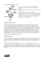
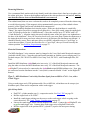
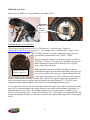
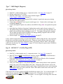
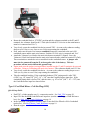
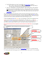
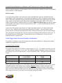
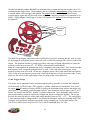
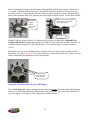
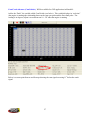
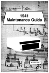
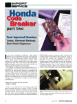
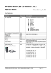
GEN3 Powertrain Controller
Ignition Setup Tutorial
For Use with the GEN3 Pro SEFI Powertrain Systems
February 2009 – Rev 1.1
The installation and set-up of the following ignition configurations will be explained in this tutorial.
For additional information on ignition systems, not listed below, refer to the GEN3 Pro SEFI System
User’s Manual.
Ignition Types Covered in This Tutorial
1. **Stand-alone IPU Distributor Only (Go to Type_1)
2. **Modified IPU Distributor (serving as the cam sync) with a Crank Trigger Setup (Go to
Type_2)
3. **MSD Distributor Used to Only Distribute Spark from an MSD 6A/7A/8A,… box, with a
Crank Trigger. (Go to Type_3
4. **MSD 2340 Cam Sync Distributor with a Crank Trigger Setup (Go to Type_4 )
5. **MSD All-in-One, Crank and Cam Sync Distributor (Go to Type_5)
6. GM’s CAM Sync Drive with BigStuff3’s 24 Tooth Crank Wheel. (Go to Type_6 )
7. MSD Mag44 Magneto (Go to Type_7)
8. GM LS1/2/7 COP System (Go toType_8 )
9. Ford Mod Motor COP System (Go toType_9 )
**If using a MSD8 CD ignition box, a pullup resistor needs to be installed between the ignition
(+12V) post and Mag + post on the side of the MSD8 ignition box! A minimum of a 900 Ohm
min (to 1K max), .125 Watt min (to 2 Watt max) resistor is needed. See Pullup_Resistor_Installation
A “Quick Setup Guide” is provided for each ignition system outlined in this tutorial. The “Quick
Setup Guides” briefly describe steps required for each ignition system setup. Detailed explanations of
some of the steps, outlined in the “Quick Setup Guide”, are provided at the end of this tutorial in a
section titled “Specific Details” and in other locations throughout this tutorial. Hyperlinks and page
numbers are provided in the “Quick Setup Guide” sections to assist in quickly locating the detailed
information.
BigStuff3’s GEN3 ECU uses a “Delay-back” Ignition Control Strategy.
Many competitive systems use a “feed-forward” ignition strategy, where the ECU has to forecast, or
predict, the next timing event, 90o before it will occur. The ECU predicts the next timing event based
on a constant engine speed assumption. If there is a transient event, and the engine accelerates or
decelerates the ECU’s timing forecast or prediction becomes inaccurate, resulting in retarded or
advanced timing.
BigStuff3 employs a “delay-back” strategy, where the ignition timing forecast or prediction occurs
within several degrees of the actual “Crank Reference” signal, thus significantly reducing timing
fluctuations during transient events. The difference may not seem significant, but it can result in
timing inaccuracies during conditions when accurate timing is critical!
1
Type 1 - Stand-alone Distributor (no cam sync signal or crank trigger used)
Stand Alone Distributor Overview
A stand-alone IPU distributor can be used with the GEN3 Pro SEFI system for sequential fuel and
spark control. “Individual Cylinder” fuel control can be implemented (using the Individual Cylinder
Fuel correction table in the BigComm software), but a standalone IPU distributor is not setup to supply
a camshaft synchronization (sync) signal to the ECU. Without the cam sync signal (every 360o of cam
rotation) there will be no way to take advantage of “fuel-phasing”, controlling the point BTDC, when
the fuel is injected into the cylinder, or individual cylinder timing control. However, the injectors will
fire sequentially (once per induction cycle), allowing the pulse width to be doubled compared to a
Bank-to-Bank (B2B) system, which fires the injector twice (per cylinder) per induction cycle (2 revs).
The bigger idle pulse width (roughly double the B2B) accomplishes better stroke to stroke repeatability
of the injector resulting in better idle quality, with high flow injectors.
Quick Setup Guide
•
•
•
•
•
•
•
•
•
•
•
•
•
•
Lock out the centrifugal advance. See Locking_Out_the_Cent_Advance on page 3
Find TDC, cylinder number one (1), compression stroke. See Find_TDC on page 20
Roll the engine back to 50o BTDC number 1 compression.
Measuring_Distances_on_the_Dampener on page 20.
Install the distributor. Make sure it is fully seated by “bumping” the starter until it engages the
oil pump drive while applying a light downward pressure.
Line one of the reluctors up with the pole piece inside the distributor.
Tighten down the distributor.
Roll the engine back to the position BTDC (cylinder 1) equal to the ignition timing the engine
will see at maximum power.
Phase the rotor and/or reluctor. See Rotor_Phasing & Reluctor_Repositioning on page 23.
Connect the red BigStuff3 wire to the purple/black striped MSD distributor wire. Connect
other Distributor wire to BigStuff3 black wire. See Electrical_Connections on page 3
Connect the BigStuff3 points wire (white) to the MSD ignition box points input.
In the BigComm Software (Operating Configuration), set the crank reference setting to 50. See
Setting_The_Crank_Reference on page 25.
Start the engine.
Using a timing light, verify that the BigStuff3 “Dash” timing advance value is the timing value
at the crank. Change the crank reference value (up or down) until the “Dash” value and the
crank value are the same. See Dash_Window on page 29.
Dynamically check the rotor phase. See Dynamically_Checking_Rotor_Phasing on page 30.
When using an IPU distributor, the centrifugal advance needs to be “Locked Out” (see below). The
BigStuff3 ECU will control the timing advance via the spark map configured in the ECU.
2
Locking Out the Centrifugal Advance
1. Remove the advance components including the springs,
weights, and the advance stop bushing from the advance
assembly.
2. Remove the roll-pin from the drive gear and remove the gear
from the shaft.
3. Slide the shaft two inches out of the housing.
4. Rotate the shaft 180° and insert the advance stop bushing pin
into the small hole on the advance plate (see illustration below).
5. Install the locknut and washer to the advance stop bushing
pin. This locks the advance in place. Do not over tighten.
6. Install the drive gear and roll-pin.
Installing the IPU Distributor
Rotate the engine so that the number 1 cylinder is Top Dead Center (TDC) (compression stroke).
Then, rotate the engine back or Before TDC (BTDC) the number of crankshaft degrees equal to the
maximum timing advance the engine will run at, plus 5o. Keeping with the example from above,
assume the maximum advance you plan to run is 45o (high speed/light load), add 5o to this number. So
rotate the engine to 50o BTDC #1 compression. Drop the distributor into the engine, then “bump” the
starter until it engages the oil pump drive while applying a light downward pressure. Once the oil
pump drive is engaged, rotate the engine back to 50o BTDC #1 compression. Turn the base of the
distributor so that the center of the reluctor aligns with the distributor pole piece. MSD distributors, use
a BLUE magnetic assembly (pole piece) with the 2 wires running out of it. Once aligned, tighten
down the distributor, reinstall the cap and wires.
Electrical Connections
The MSD distributor 2 wire connector must be changed to the 2-way black male Metripack connector
(included with IPU kits). Crimp the seals and female terminals on with the correct crimping tool. Use
Packard crimper, PN 12014254 or MSD’s Pro-Crimp Tool, PN 35051, with Weathertight Dies, PN
3509.
Install the MSD distributor violet/black wire into cavity “A” of the black Metripack connector and
plug the other wire from the MSD distributor into cavity “B” of the black Metripack connector. The
red BigStuff3 wire needs to be connected to the violet/black striped MSD distributor wire. Next, plug
the connector from the distributor into the 2 wire (black) connector labeled “Crank” on the BigStuff3
harness.
3
Type 2 - Modified distributor (to serve as the cam sync) to be used with a crank trigger
setup
The cam sync drive provides a signal (every 360o of cam rotation) that allows for cylinder “fuelphasing” (controlling the point, BTDC, when the fuel is injected into the cylinder) and individual
cylinder “timing control”.
The cam sync signal, references the start of an injection or ignition firing sequence, and needs to occur
10o - 20o before the crank signal. The cam sync signal informs the ECU of the position of the number 1
cylinder. After the cam sync signal, the next input received by the ECU is the crank signal from the
crank trigger.
Quick Setup Guide
•
•
•
•
•
•
•
•
•
•
•
•
•
•
•
•
•
•
If applicable, lock out the centrifugal advance. See Locking_Out_the_Cent_Advance on page
3.
Find TDC, cylinder number one (1), compression stroke. See Find_TDC on page 20.
Roll the engine back to 50o BTDC. See Measuring_Distances_on_the_Dampener on page 20.
Install the crank trigger. Line up the sensor with the magnet. make sure the arrows on the
crank trigger wheel are going on the correct direction! See Crank_Trigger_Considerations on
page 21.
Connect the crank trigger green wire to the BigStuff3 red wire. Connect the other crank trigger
wire to BigStuff3 black wire.
Roll the engine back to 70o BTDC cylinder number 1 compression
Install the distributor and make sure it is fully seated by “bumping” the starter until it engages
the oil pump drive while applying a light downward pressure.
Line up the reluctor that is closest to the pole piece and mark it with permanent marker.
Remove the seven other reluctors. See Removing_Reluctors on page 6.
Re-install the modified distributor, making sure the remaining reluctor is aligned with pole
piece.
Tighten down the distributor
Roll the engine back to the position BTDC (cylinder 1) equal to the ignition timing the engine
will see at maximum power.
Phase the rotor and/or reluctor. See Rotor_Phasing & Reluctor_Repositioning on page 23.
Connect the red BigStuff3 wire to the violet/black striped MSD distributor wire. Connect
other Distributor wire to BigStuff3 black wire. See Type_2_Electrical_Connectionson page 6.
Connect the BigStuff3 points wire (white) to the MSD ignition box points input.
In the BigComm Software (Operating Configuration), set the crank reference setting to 50. See
Setting_The_Crank_Reference on page 25.
Start the engine.
Use the “CamCrkAdv” window in the Dash to adjust the cam sync to 15o- 20o. This is the
number of crank shaft degrees that the cam sync pulse occurs before the crank pulse. Loosen
and adjust the cam sync (modified distributor) until the cam sync occurs at least 15o- 20o before
the crank. Re-tighten the cam sync (modified distributor). See CamCrkAdv on page 27.
Lastly, with the engine still running verify that the BigStuff3 “Dash” timing advance value
equals the timing value seen (with a timing light) at the crank. Change the crank reference
4
•
•
value in the Crank Trigger window (in the Operating Configuration table), up or down, until
the “Dash” value and the crank value are the same. See Setting_The_Crank_Reference on page
25.
Dynamically check the rotor phase. See Dynamically_Checking_Rotor_Phasing on page 30.
Lastly, you will want to verify cam synchronization. See Verifying_Synchronization on page
11.
Modifying an Existing Distributor to Create a CAM Sync Signal
If you already have an IPU distributor, the possibility exists to modify it so that it can be used to
provide the cam sync signal. If the distributor has reluctor tabs (interrupts for each cylinder), 7 of the 8
reluctor tabs (for a V8) can be removed to create a cam sync distributor. Please carefully read this
section before removing the reluctor tabs from the distributor.
Note: If you decide to modify a distributor to provide the cam sync signal, the mechanical advance
must also to be locked out! See Locking_Out_the_Cent_Advance or go to page 3, then the section
outlining this procedure.
Reluctor tab
Setting Up the IPU Distributor to be used as the Cam Sync
Once the distributor has been “locked out” (the mechanical advance capabilities have been removed), it
needs to be installed in the engine to determine which reluctors (7 of 8 for a V8) need to be removed to
create the cam sync signal. The cam sync (signal) must occur before the Crank signal.
Start by rotating the crank to 10o – 20o before the “Crank Reference” angle described above (this could
be up to 70o BTDC with a 50o “Crank Reference”). Install the distributor making sure that it is
installed in the engine in an orientation that allows the plug wires to be easily routed to their respective
cylinders and that the leads (wires from the pickup) can be easily connected to the main wire harness.
Note: For engines with the distributor mounted in the front, an extension jumper will be needed to
interface with the “Cam” connector on the BigStuff3 harness. Remove the distributor cap and rotor
and align the pickup pole piece with reluctor. The distributor may need to be loosened so that the base
of the distributor can be moved slightly to ensure an exact alignment between the senor pole piece and
reluctor. The reluctor and pole piece are said to be “in-phase” when they are perfectly aligned.
5
Removing Reluctors
Use a permanent black marker and clearly identify (mark) the reluctor that is lined up or in-phase with
the sensor pole piece. Remove the distributor and remove the reluctors that were not marked, making
sure that the reluctor that was identified/marked is not removed!
The residual metal, that was once a reluctor tab, needs to be completely removed from the reluctor ring
to avoid false triggering. If the magnetic pickup unintentionally senses any of the residual reluctor
material, a false signal could result with undesired consequences!
Reinstall the modified distributor back into the engine. Make sure the distributor is seated fully.
“Bump”, the engine if need be to engage the oil pump drive. Once fully seated, rotate the engine back
to the 10-20 degrees before the “Crank Reference” value (this could be up to 70o BTDC with a 50o
“Crank Reference”). Align the single reluctor tab with the center of the pole piece; now tighten down
the base of the distributor. Next you’ll need to check/verify your rotor phase. Rotate the engine now to
the timing desired for max power note where the rotor is in relation to the distributor cap terminal. It
should be directly across. If not, and space allows, use MSD’s adjustable rotor or “Cap-a Dapt” to
correct the rotor phase. If space does not allow for a “Cap-a Dapt”, then you’ll need to modify the
reluctor position. See Reluctor_Repositioning on page 23.
Electrical Connections
The MSD distributor 2 wire connector must be changed to the 2-way black male Metripack connector
(included with IPU kits). Crimp the seals and female terminals on with the correct crimping tool. Use
Packard crimper, PN 12014254 or MSD’s Pro-Crimp Tool, PN 35051, with Weathertight Dies, PN
3509.
Install the MSD distributor violet/black wire into cavity “A” of the black Metripack connector and
plug the other wire from the MSD distributor into cavity “B” of the black Metripack connector. The
red BigStuff3 wire needs to be connected to the violet/black striped MSD distributor wire. Next, plug
the connector from the distributor into the 2 wire (black) connector labeled “Crank” on the BigStuff3
harness.
Type 3 - MSD Distributor Used to Only Distribute Spark from an MSD 6A/7A/8… box, with a
Crank Trigger.
Using a crank trigger and a CDI ignition module, like an MSD 6A, a distributor can be setup to just
distribute spark, when used in conjunction with a crank trigger.
Quick Setup Guide
•
•
•
•
•
Find TDC, cylinder number one (1), compression stroke. See Find_TDC on page 20.
Roll the engine back to 50o BTDC.
Install the crank trigger making sure the arrows on the crank trigger wheel are going on the
correct direction! See Crank_Trigger_Considerations on page 21.
Line up the crank trigger sensor with the magnet in the wheel. Connect the red BigStuff3 wire
to green crank trigger wire. Connect other crank trigger wire to BigStuff3 black wire.
Roll the engine back to the position BTDC (cylinder 1) equal to the max power timing.
6
•
•
•
•
•
•
Install the distributor then “bump” the starter until it engages the oil pump drive while applying
a light downward pressure. Once the oil pump drive is engaged, rotate the engine back to the
timing mark on the dampener that will represent the maximum timing the engine will see at full
power. Turn the base of the distributor so that the distributor cap terminal for cylinder number
1 is aligned with the rotor in this position. Tighten the distributor down.
Connect the BigStuff3 points wire (white) to the MSD ignition box points input.
In the BigComm Software (Operating Configuration), set the crank reference setting to 50. See
Setting_The_Crank_Reference on page 25.
Start the engine, with the engine still running verify that the BigStuff3 “Dash” timing advance
value equals the timing value seen (with a timing light) at the crank. Change the crank
reference value in the Crank Trigger window (in the Operating Configuration table), up or
down, until the “Dash” value and the crank value are the same. See Dash_Window on page 29.
Dynamically check the rotor phase. See Dynamically_Checking_Rotor_Phasing on page 30.
Lastly, you will want to verify cam synchronization. See Verifying_Synchronization on page
11.
Type 4 - IPU Cam Sync Distributor (MSD P/N 2340) with a Crank Trigger Setup
Quick Setup Guide
•
•
•
•
•
•
•
•
•
•
•
•
•
•
•
Find TDC, cylinder number one (1), compression stroke. See Find_TDC on page 20.
Roll the engine back to 50o BTDC.
Install the crank trigger. Line up the sensor with the magnet. See
Crank_Trigger_Considerations on page 21.
Roll the engine back to 70o BTDC cylinder number 1 compression
Install the distributor then “bump” the starter until it engages the oil pump drive while applying
a light downward pressure. Make sure it is fully seated.
Line up the magnet with the pole piece inside the distributor with the pickup.
Tighten down the distributor
Roll the engine back to the position BTDC (cylinder 1) equal to the max power timing.
Phase the rotor and/or reluctor.
Connect the red BigStuff3 wire to green distributor wire. Connect other Distributor wire to
BigStuff3 black wire.
Connect the BigStuff3 points wire (white) to the MSD ignition box points input.
In the BigComm Software (Operating Configuration), set the crank reference setting to 50.
Start the engine. See Setting_The_Crank_Reference on page 25.
Use the “CamCrkAdv” window in the Dash to adjust the cam sync to 15o - 20o. This is the
number of crank shaft degrees that the cam sync pulse occurs before the crank pulse. Loosen
and adjust the cam sync (modified distributor) until the cam sync occurs at least 15o - 20o
before the crank. Re-tighten the cam sync (modified distributor). CamCrkAdv on page 27.
Lastly, with the engine still running verify that the BigStuff3 “Dash” timing advance value
equals the timing value seen (with a timing light) at the crank. Change the crank reference
value in the Crank Trigger window (in the Operating Configuration table), up or down, until
the “Dash” value and the crank value are the same. See Dash_Window on page 29.
7
MSD Cam Sync Drive
Shown below is MSD’s cam sync distributor, part number 2340.
Inductive
pick-up
(sensor)
Installing the Cam Sync Distributor
The cam sync (signal) needs to occur 10o – 20o before the “Crank Reference” angle (see
Setting_The_Crank_Reference on page 25 ). For example, if the “Crank Reference” angle is set to
45o BTDC (number 1 cylinder, compression stroke), the cam
Magnet
sync should be installed between 55o and 65o‘s BTDC.
Start by rotating the engine to the desired cam sync position (55 –
65o BTDC #1 Comp). Next remove the distributor cap and rotor.
While aligning the magnet with the Inductive Pick-Up (IPU)
sensor, drop it into the engine.
Note: Install the Cam Sync Distributor making sure that it is
installed in the engine in an orientation that allows the plug wires
to be easily routed to their respective cylinders and that the leads
(wires from the pickup) can be easily connected to the main wire
harness. Make sure the distributor is seated fully. “Bump” the engine to engage the oil pump drive.
Once fully seated, rotate the engine back to the desired cam sync position (55 – 65o BTDC), then
realign the magnet with the Inductive Pick-Up (IPU) sensor and tighten the base down.
Magnet carrier. Rotor
attaches to this piece
Next you’ll need to check/verify your rotor phase. Rotate the engine now to the timing desired for max
power (20o for boosted engines) note where the rotor is in relation to the distributor cap terminal. It
should be directly across. If not, use an MSD adjustable rotor or if space allows, an MSD “Cap-aDapt” to correct the rotor phase. If space does not allow for a “Cap-a-Dapt” or the adjustable rotor did
not provide adequate phasing you will need to reposition the magnet in the magnet carrier as described
below.
8
Repositioning the Magnet
You may have to reposition the magnet in the magnet carrier, if the rotor phase is unacceptable for the
desired timing at peak power. Next, rotate the engine back to the 10 - 20o before the “Crank
Reference” (55 – 65o BTDC). Once there, remove the magnet carrier and note the position of the
Inductive Pick-Up (IPU) sensor and mark the magnet carrier where the IPU aligns. Remove the
magnet carrier by loosening the center flush mount cap screw. Next drill and re-epoxy the magnet into
the carrier at the new/marked location.
Important: Make sure the magnet is reinstalled in the correct direction! Note: the Inductive Pick-Up
(IPU) sensor may have to be moved instead of the magnet, if there is not enough material to
encapsulate the magnet in the new position.
Note: The cam sync signal must never occur at the same time as the crank trigger signal. If this
occurs, the ECU will set the Cam_Sync error flag. You can record this in the Replay datalog. Once the
Cam_Sync error is set, the individual cylinder timing corrections could jump to the wrong cylinder
causing engine misfire.
The MSD IPU Cam Sync Distributor 2 wire distributor connector must be changed to the 2 way gray
male Metripack connector (included in IPU kits). Crimp the seals and female terminals on with the
correct crimping tool. Use Packard crimper, PN 12014254 or MSD’s Pro-Crimp Tool, PN 35051, with
Weathertight Dies, PN 3509. Install the MSD IPU Cam Sync Distributor green wire into cavity “A” of
the gray Metripack connector and plug it into the 2 wire gray connector labeled “Cam” on the
BigStuff3 harness. The BigStuff3 red wire must connect to the MSD green wire.
HED Cam Sync Transducer
BigStuff can also supply a Hall Effect transducer (HED) and magnet for
DIY cam sync pulses (PN JMI-007-013). See picture below. The HED
output is ideal for near zero speed sensing applications. It can be used
to provide the cam sync pulse to adapt Coil on Plug ignition systems to
virtually any application. It may also be used in place of the 2 wire
pickup on MSD All-In-One Distributors (PN 2345 & 2382).
9
Type 5 - All-in-One, Crank and Cam Sync Distributor
Currently MSD makes two all-in-one cam and crank (signal) distributors (see below).
MSD all-in-one Ford
distributor Part Number 2382
Crank
Pickup
MSD all-in-one Chevy
distributor Part Number 2345
Camshaft
pickup
The All-In-One IPU distributor has both a cam and crank sensor built into a single unit.
Quick Setup Guide
•
•
•
•
•
•
•
•
•
•
•
•
Find TDC, cylinder number one (1), compression stroke. See Find_TDC on page 20.
Roll the engine back to 50o BTDC number 1 compression.
Install the distributor. Make sure it is fully seated.
Line a reluctor up with the pole piece inside the distributor.
Tighten down the distributor.
Roll the engine back to the position BTDC (cylinder 1) equal to the max power timing.
Phase the rotor and/or reluctor. See Rotor_Phasing and Reluctor_Repositioning on page 23.
Connect the red BigStuff3 wire to the violet/black distributor wire. Connect other Distributor
wire to BigStuff3 black wire.
Connect the BigStuff3 points wire (white) to the MSD ignition box points input.
In the BigComm Software (Operating Configuration), set the crank reference setting to 50. See
Setting_The_Crank_Reference on page 25.
Verify the BigStuff3 “Dash” timing advance value to the timing at the crank. Change the crank
reference value (up or down) until the “Dash” value and the crank value are the same. See
Dash_Window on page 29.
Follow the additional step below to setup the cam sync.
The cam sync signal (every 360o of cam rotation) allows the user to take advantage of cylinder “fuelphasing” (controlling the point, BTDC, when the fuel is injected into the cylinder) and individual
cylinder “timing control”. With both of the All-In-One IPU distributors (PNs 2345 & 2382) you will
need to change the reluctors to get good rotor phase for most applications. See Reluctor_Repositioning
on page 23.
10
The MSD All-In-One Distributor 2 wire connector (wires from the blue pole piece) must be changed to
the 2 way black male Metripack connector (included in IPU kits). Crimp the seals and female
terminals on with the correct crimping tool. Use Packard crimper, PN 12014254 or MSD’s Pro-Crimp
Tool, PN 35051, with Weathertight Dies, PN 3509.
Install the All-In-One Distributor violet/black wire into cavity “A” of the black Metripack connector
and plug it into the 2 wire black connector labeled “Crank” on the BigStuff3 harness.
The MSD All-In-One Distributor 2 wire connector (green and purple wires) must be changed to the 2
way gray male Metripack connector (included in IPU kits). Crimp the seals and female terminals on
with the correct crimping tool. Install the MSD All-In-One Distributor green wire into cavity “A” of
the gray Metripack connector and plug it into the 2 wire gray connector labeled “Cam” on the
BigStuff3 harness. The green MSD wire needs to connect to the red BigStuff3 wire.
How to adjust the cam sync signal
In order to adjust the cam sync signal, loosen the 2 screws in the retaining collar. The collar should
slide easily if the screws are loose enough. Add to the “Dash”, the variable called CamCrkAdv see
CamCrkAdv on page 27. This variable displays in real time the relationship between the cam sync
pulse and the first crank pulse. The reading is in degrees; adjust it to read between 10 – 20o once the
engine is running.
Note!!: In order for the value to move off of 0o, the engine rpm must exceed 2000 rpm. This is the rpm
above which the ECU tries to synchronize. If the reading stays at 0 degrees continuously regardless of
the rpm, the cam sync pulse is not making it to the ECU. Check the wires for any disconnects/shorts.
Because the cam sync window is so wide, it is possible that the synchronization could be occurring on
the wrong cylinder.
Verifying Cam Synchronization
To verify that the cam sync is correct, go to the main BigComm tool bar. Under “Individual Cylinder”
go to Individual Spark. In the table, retard the timing for Cyl. 1 by 10o, with the timing light verify the
timing retards for Cyl.1 by 10o. If not, slide the cam sensor the other direction until it again reads
between 10 – 20o. If the timing now retards, the system is synchronized and no Cam_Sync errors
should occur.
You can also type the letters “B A L” simultaneously and a real time display of the synchronization
status will appear in the upper right toolbar. If the synchronizer is gray and is rotating eccentrically,
everything is alright. However, if it’s red, problems exist.
Note: Remember the engine rpm must exceed 2000 rpm before synchronization is attempted in
distributor based ECUs. So the synchronizer will be red initially below 2000 rpm. The individual
cylinder timing retard still needs to be verified, even though the synchronizer is gray. This is just a
quick test to see if synchronization is taking place. Important: For COP ECUs (LSx engine using HED
sensors), the synchronization status is provided immediately during cranking, so there is no need to rev
the engine to 2000 rpm.
11
Type 6 - Using GM’s Oil Pump/Cam Sync Drive (P/N 1104068) Used in Conjunction
with BigStuff3’s 24 tooth Wheel. For standalone Coil-on-Plug (COP) systems.
Quick Setup Guide
1. Find TDC, cylinder number one (1), compression stroke. See Find_TDC on page 20.
2. Install the GM cam sync drive at TDC, then “bump” the starter until it engages the oil pump
drive while applying a light downward pressure. Make sure it is fully seated and tighten it
down.
3. Modify the Bigstuff3 main wire harness Cam connector, as described below, and connect the
harness to the GM cam sync drive. See GM_Cam_Sync_Wiring_Mods on page 12.
4. Find the falling edge from the Cam sync drive. See GM_Cam_Sync_Falling_Edge on page 15.
5. Roll the crankshaft forward (clockwise) 10o after the reading taken from the cam falling edge
test. For example, if the cam falling edge occurred at 2o before TDC (BTDC), roll the crank to
8o ATDC
6. Align the 2 wire crank sensor on any one of the teeth, on the BigStuff3 24 tooth wheel. Connect
purple sensor wire to red BS3 harness wire and the green sensor wire to the black BS3 wire.
See LS1_2_Wire_Sensor_Connection for electrical connections if using an LS1 main harness.
7. Since we moved the crankshaft 8o after TDC (ATDC) subtract 8o from 360o (360o - 8o = 352o)
and input 352o into the COP Crank Reference input box (not the crank Trigger Crank
Reference box). Setting_the_LS1_Crank_Reference on page 28.
8. In the Operating Configuration window, input 24 into the Pulse Wheels cell for Crankshaft
(pulses/rev). See Setting_the_LS1_Crank_Reference on page 28.
9. Start the engine.
10. Use the “CamCrkAdv” window in the Dash to adjust the crank sensor so that the value
displayed in the “CamCrkAdv” window is 10. Tighten the crank sensor. See CamCrkAdv on
page 27.
11. With the engine still running, verify that the BigStuff3 “Dash” timing advance value equals the
timing value seen (with a timing light) at the crank. Change the crank reference value in the
COP Crank Reference input box (not the crank Trigger Crank Reference box), in the Operating
Configuration table, up or down, until the “Dash” value and the crank value are the same. See
Dash_Window on page 29.
12. Lastly, you will want to verify cam synchronization. See Verifying_Synchronization on page.
The following section will explain more specifically how to install a camshaft synchronizer (cam
sync), and how to set it up for use with BigStuff3’s GEN3 COP Sequential Electronic Fuel System
(SEFI) system.
Using GM’s Cam Sync Drive
The BigStuff3 LS1 Cam connector will not plug directly into the GM Cam synch drive! The
connectors look similar, but they are different. The terminal pin letters (A, B & C) on the two
connectors are in opposite order, so the BigStuff3 LS1 Cam connector (not the terminals, so don’t cut
the wires!) will need to be removed from the harness and the connector identified below will need to
be installed.
12
The table below shows the position the BigStuff3 Cam wires need to occupy in the new connector
housing (positions A, B & C). The new connector housing has the A, B & C terminal locations
molded into the housing.
GM Cam Synch Drive
Pin A
Pin B
Pin C
BS3 LS1 CAM Connector
Pink/black stripe wire
Brown/white stripe wire
Red wire
Pin Function
Ground
Signal
+12V
The Delphi tool, required to remove the terminal pins from the BigStuff3 Cam housing, is also shown
below.
Delphi terminal removal tool P/N 12094429 can be purchased for about $10 from this website link
http://www.lsxtune.com/shop/product_info.php/products_id/1080.
Secondary
lock – white
in color
Steps to remove the BigStuff3 Cam connector from the Main Wire Harness
First, remove the secondary lock (white plastic part on the back of the connector) from the connector
housing. Next, insert the Delphi terminal removal tool into the uppermost section of the housing as
shown in the photo above. While inserting the tool into the pin cavity, gently pull on the wire. The
wire should release without having to aggressively tug on it.
Next, remove all three wires in the same fashion. Make sure that the terminal retention tabs (very
small metal tabs on the back of the terminal pins) are raised back up so that they will lock
correctly into the new connector housing. Failure to raise the terminal retention tabs could
result in a failed connection between the connector and the cam sync drive.
Terminal retention tab must be
pulled back to this position after
removing it from the BS3 Cam
connector housing.
13
Next, install the terminal pins into the new connector housing per the table above. Lastly, snap the
secondary lock back onto the back of the new connector housing.
Plug the connector into the cam sync drive. The terminal locations (A, B, & C) molded into the new
connector housing are in the same order (based on the connector tab) as is shown below for the Cam
Sync drive.
Pin B – Signal – to
BS3 LS1 Cam
Connector – Brown
Wire
Connector
locking tab
GM’s Oil Pump/Cam
Synch Drive (P/N 1104068)
Pin C – +12V –
to BS3 LS1 Cam
Connector -Red
Wire
Pin A –
Ground – to
BS3 LS1 Cam
Connector Pink Wire
Packard Connector assembly required for BigStuff3 Harness to Cam Synch drive interface. The kit
outlined below is available from BigStuff3.
Quantity
1
3
3
1
Part Number
12110293
12048074
12048086
12052845
Description
Packard, 3-way Male connector
Packard, Terminal
Packard, Cable Seal
Packard, Secondary Lock
Installing the Cam Sync Drive
To realize the full benefits of the GEN3’s precise timing and individual cylinder fuel control, Top
Dead Center (TDC) for cylinder 1 (compression stroke) needs to be determined and marked on the
dampener. Rotate the engine to TDC, number 1 cylinder, compression (stroke). Install the cam sync
drive so that the gears on the drive and cam are engaged and the connector can be easily installed.
While applying pressure on the cam sync drive, turn the engine over until it fully engages with the cam
shaft. Tighten the cam sync drive clamp securely. Make the electrical connections to the cam sync
drive.
14
Find GM Cam Sync Falling Edge
To find the Cam Falling Edge a voltmeter and a jumper wire are required.. A crankshaft degree wheel
is also recommended.
The following outlines the process.
•
Roll the crankshaft back 30o Before Top Dead Center (BTDC). A crankshaft degree wheel or
balancer timing tape will help expedite the process. If neither is available, the following
formula can be used to measure the distance, on the surface of the balancer that equals 30o.
Multiply the diameter of the balancer by 3.14. Divide the result by 360, and then
multiply by 30 (representing the 30o).
Example based on a 7” balancer: 7 x 3.14= 21.98. 21.98/360= .06105” (per
degree). .06105” x 30o =1.8316”. From the TDC mark on the balancer, measure
forward (clockwise) about 1-13/16” and make a mark, which will represent 30o
BTDC.
•
•
Make sure the main wire harness camshaft connector is attached to the stock LS1 camshaft
sensor and the main wire harness Switched 12-Volt wire is connected and “live”. The main
harness battery connections also must be in place.
Attach the Voltmeter’s red lead to the main wire harness terminal E3 (Signal) and the
Voltmeter’s black lead to the main wire harness terminal J2 (Gnd). These terminals are
attached to wires routed back to the camshaft sensor. The easiest way to accomplish this is to
insert sewing needles between the Voltmeter’s positive and negative alligator clamps, and then
push them into the aforementioned header connector terminals. Also, a jumper wire must
also be connected from pin J2 to the negative side of the battery. This test procedure will
not work without this ground strap.
Note: Make sure the probes (sewing needles) inserted into the E3 and J2 terminals do not
touch each other. Doing so will damage the main wire harness!
Note: It is important to use probes with tapered tips (like sewing needles) rather than blunt tipped
probes (like paper clips) to avoid damaging the main harness header connector terminals
•
•
Rotate the crankshaft back to 30o BTDC position and the voltmeter attached to the E3 and J2
terminals, the voltmeter should read 12 Volts (the Switched 12-Volt wire on the main harness
must be is connected and “live”).
Very slowly, rotate the crankshaft clockwise towards TDC. As soon as the voltmeter reading
drops to zero Volts (or very close to zero Volts) stop rotating the crankshaft. Make note (write
it down) of the reading from the crankshaft degree wheel. Use this value in calculations shown
in bullet 7, on page 12 GM_Sync_Cam_Value_Input.
15
Type 7 – MSD Mag44 (Magneto)
Quick Setup Guide
•
•
•
•
•
•
•
•
•
•
Find TDC, cylinder number one (1), compression stroke. See Find_TDC on page 20.
Roll the engine back to 50o BTDC.
Install the crank trigger. Line up the sensor with the magnet. See
Crank_Trigger_Considerations on page 21.
Roll the engine forward to the position BTDC (cylinder 1) equal to the max power timing.
Phase the rotor and/or reluctor.
Connect the red BigStuff3 wire to green crank trigger wire. Connect other crank trigger wire
to BigStuff3 black wire.
Connect the BigStuff3 points wire (white) to the MSD Pro Mag violet wire ignition box points
input.
In the BigComm Software (Operating Configuration), set the crank reference setting to 50.
The ignition timing during cranking must be set to 25o. Go into the spark map and make sure
all the cells used during engine cranking are set to 25o. The engine will start on the magneto.
The Pro Mag 44 requires about 250 RPM to fire during cranking. BigStuff3 takes over and
controls the spark timing above 1,000 rpm.
Start the engine. See Setting_The_Crank_Reference on page 25.
Lastly, with the engine still running verify that the BigStuff3 “Dash” timing advance value equals the
timing value seen (with a timing light) at the crank. Change the crank reference value in the Crank
Trigger window (in the Operating Configuration table), up or down, until the “Dash” value and the
crank value are the same. See Dash_Window on page 29. The Pro Mag 44 requires about 250 RPM to
fire during cranking.
Type 8 – GM LS1/2/7 - Coil-On-Plug (COP)
Quick Setup Guide
•
•
•
•
•
Find TDC, cylinder number one (1), compression stroke. See Find_TDC on page 20.
Input 350o into the COP Crank Reference input box (not the crank Trigger Crank Reference
box). See Setting_the_LS1_Crank_Reference on page 28.
In the Operating Configuration window, input 24 into the Pulse Wheels cell for Crankshaft
(pulses/rev). See Setting_the_LS1_Crank_Reference on page 28.
Start the engine.
Lastly, use a timing light to verify that the BigStuff3 “Dash” timing advance value equals the
timing value seen (with a timing light) at the crank. Change the crank reference value in the
COP Crank Reference input box (not the crank Trigger Crank Reference box), in the Operating
Configuration table, up or down, until the “Dash” value and the crank value are the same. See
Dash_Window on page 29.
If the engine does not start, change the COP Crank Reference input to 360. Try to start the engine. If
it does not start, input the COP Crank Reference input to 370. If it still does not start, there is a
relationship problem between the cam and crank signals. The cam signal is occurring at the same time
16
as the crank signal. To confirm this, type the letters B-A-L simultaneously see B_A_L on page 30.
Make sure the PC is communicating with the GEN3 ECU. A small box will appear near the tool bar in
the upper right corner of the BigComm software screen. If the synchronizer ball is gray and is rotating
eccentrically within the box, the cam signal is occurring before the crank signal. If the ball turns red, a
problem exists, since the cam signal is occurring at the same time as the crank signal. To alleviate this
problem, the cam sync sensor needs to be replaced, or modified so that the cam sync pulse occurs
before the crank signal. Call BigStuff3 for further assistance if the ball remains red.
Setting the COP Crank Reference Setting – LS1
To find the Cam and Crank Falling Edges (the 1st crank falling edge after the cam falling edge), a
voltmeter and a jumper wire are required.. A crankshaft degree wheel is also recommended.
The following outlines the process.
•
Roll the crankshaft back 30o Before Top Dead Center (BTDC). A crankshaft degree wheel or
balancer timing tape will help expedite the process. If neither is available, the following
formula can be used to measure the distance, on the surface of the balancer that equals 30o.
Multiply the diameter of the balancer by 3.14. Divide the result by 360, and then
multiply by 30 (representing the 30o).
Example based on a 7” balancer: 7 x 3.14= 21.98. 21.98/360= .06105” (per
degree). .06105” x 30o =1.8316”. From the TDC mark on the balancer, measure
forward (clockwise) about 1-13/16” and make a mark, which will represent 30o
BTDC.
•
•
Next, make sure the main wire harness camshaft connector is attached to the stock LS1
camshaft sensor and the main wire harness Switched 12-Volt wire is connected and “live”. The
main harness battery connections also must be in place.
Attach the Voltmeter’s red lead to the main wire harness terminal E3 (Signal) and the
Voltmeter’s black lead to the main wire harness terminal J2 (Gnd). These terminals are
attached to wires routed back to the camshaft sensor. The easiest way to accomplish this is to
insert sewing needles between the Voltmeter’s positive and negative alligator clamps, and then
push them into the aforementioned header connector terminals. Also, a jumper wire must
also be connected from pin J2 to the negative side of the battery. This test procedure will
not work without this ground strap.
Note: Make sure the probes (sewing needles) inserted into the E3 and J2 terminals do not
touch each other. Doing so will damage the main wire harness!
Note: It is important to use probes with tapered tips (like sewing needles) rather than blunt
tipped probes (like paper clips) to avoid damaging the main harness header connector
terminals.
17
•
•
•
•
•
•
•
Rotate the crankshaft back to 30o BTDC position and the voltmeter attached to the E3 and J2
terminals, the voltmeter should read 12 Volts (the Switched 12-Volt wire on the main harness
must be is connected and “live”).
Very slowly, rotate the crankshaft clockwise towards TDC. As soon as the voltmeter reading
drops to zero Volts (or very close to zero Volts) stop rotating the crankshaft.
Next, make sure the main wire harness crankshaft connector is attached to the stock LS1
crankshaft sensor and the main wire harness, Switched 12-Volt wire is connected and “live”.
Attach the Voltmeter’s red lead to the main wire harness terminal J3 (Signal). Leave the
Voltmeter’s black lead inserted into the main wire harness header connector terminal J2 (Gnd).
These terminals are attached to wires routed back to the crankshaft sensor. A jumper wire
must also be connected from pin J2 to the negative side of the battery. This test
procedure will not work without this ground strap.
Again, make sure the probes (sewing needles) inserted into the J3 and J2 terminals do not touch
each other. Doing so will damage the main wire harness! The voltmeter should read 12 Volts.
Very slowly, rotate the crankshaft clockwise. As soon as the voltmeter reading drops to zero
Volts (or very close to zero Volts) stop rotating the crankshaft.
Take the crankshaft reading. If the crankshaft (balancer) TDC timing mark is after TDC
(ATDC) e.g. 10o, input 350o (360o - 10o = 350o) into the Crank Reference input box. If the
crankshaft timing mark is before TDC, add the value, e.g. 10o to 360o (360o + 10o = 370o) into
the Crank Reference input box shown below.
Type 9- Ford Mod Motor - Coil-On-Plug (COP)
Quick Setup Guide
•
•
•
•
Find TDC, cylinder number one (1), compression stroke. See Find_TDC on page 20.
Input 329o into the COP Crank Reference input box (not the crank Trigger Crank Reference
box). See Mod_Motor_Crank_Reference on page 19.
In the Operating Configuration window, input 36 into the Pulse Wheels cell for Crankshaft
(pulses/rev). See Mod_Motor_Crank_Reference on page 19.
Start the engine.
18
•
•
The UEGOR reading in the “Dash” must read 28. See Dash_Window on page 29.
o Note: There is a cam sync issue if the UEGOR reading is any number other than 28.
The cam sensor will need to be moved until UEGOR reads 28.
Lastly, use a timing light to verify that the BigStuff3 “Dash” timing advance value equals the
timing value seen (with a timing light) at the crank. Change the crank reference value in the
COP Crank Reference input box (not the crank Trigger Crank Reference box), in the Operating
Configuration table, up or down, until the “Dash” value and the crank value are the same. See
Dash_Window on page 29.
The crank and cam connectors and pigtails, from the stock Ford vehicle harness must be used. The
mating 3 way connector/terminals are provided. You must connect the crank pigtail (blue with black
stripe wire) to the red wire (pin A) on the main wire harness marked Mod Crank. The other wire goes
to pin B on the main wire harness marked Mod Crank and the shield goes to pin C.
Connect the cam pigtail (blue with orange stripe wire (Mustang)) or (Dark Green (Lightning) to the
red wire (pin A) on the main wire harness marked Mod Cam. The other wire (gray with red
(Mustang)) or (light blue (Lightning) goes to pin B on the main wire harness marked Mod Cam. If
you decide to install a shield, connect it to pin C on the main wire harness marked Mod Cam.
The Override Cam Sync Test box must be checked with the Ford Mod Motors (see screen print
below)
“Crank Reference” windows in the BigComm “Operating Parameter Configuration”
Window.
Ford Mod Motor
This value must be set a 36.
Static Test
Timing
Window
Ford Mod Motor
Start with 329 here.
Ford Mod Motor
This box must be checked!
Make sure the UEGOR signal is in the “Dash” see Dash_Windowon page 29. It is used to detect the
36-1 missing tooth on the crank trigger wheel. For Ford Mod Motors it must read 28. If it is something
19
other than this number, then there is a synchronization problem between the cam and crank. The cam
sensor may need to be moved to correct the cam sync problem.
“Specific Details”
Measuring Distances on the Surface of a Dampener.
The following formula can be used to measure the distance on the radial face of the balancer. In this
example, 10o BTDC is being calculated.
Accurately measure the diameter of the dampener, then multiply the diameter by 3.14. Divide the
result by 360, and then multiply by 30 (representing the 10o).
Example based on a 7” balancer: 7 x 3.14= 21.98. 21.98/360= .06105” (per degree). .06105” x 10o
=.6105”. From the TDC mark on the balancer, measure forward (clockwise) about 5/8” and make a
mark, this will represent 10o BTDC.
“Do it Right” Find TDC
All the ignitions setups outlined in this tutorial assume the Top Dead Center (TDC) position on the
dampener equals true TDC for cylinder number 1, compression stroke. This assumption could be
robbing you of power or worse, so the best approach is to verify TDC and you’ll be assured to get the
most of your engine.
Finding TDC
TDC is the point at which the piston in cylinder #1 reaches its uppermost position in the cylinder.
Ignition timing is usually expressed as degrees before top dead center (BTDC) or after top dead center
(ATDC). A timing mark on the crankshaft dampener corresponds to the top dead center position of the
number one cylinder, compression stroke. It is important that TDC is verified. A simple process for
verifying TDC for number one (1) cylinder (compression) is outlined in the paragraphs below.
Finding TDC when the cylinder heads are on the engine
One way to find Top Dead Center (TDC) is to use a piston stop and a degree wheel. Make sure that
the piston is down in the cylinder and then thread the piston stop into the #1 spark plug hole.
Note: If your engine does not have a rigid pointer already mounted near the dampener, now is the best
time to fabricate a permanent pointer. A permanent pointer will need to be fabricated for this
procedure and to be able to continue to verify the timing in the future. A crankshaft degree wheel, or a
balancer with timing marks on it, or a timing tape is required for this procedure.
Using a Degree Wheel
Securely fasten the degree wheel to the front of the crankshaft. Next, fabricate a rigid pointer to point
at the front of the degree wheel (even though you may have a permanent pointer since the degree
wheel diameter may be larger than the dampener).
20
Using the Degreed Dampener or a Dampener with Timing Tape on it, instead of a degree wheel
Make sure that the pointer is solidly mounted so that it will not move and that you can see the numbers
on the radial face of the dampener.
TDC Procedure
Very slowly and carefully (via a breaker bar on the crankshaft bolt) rotate the crankshaft until the
piston lightly touches the piston stop. Write down the number the pointer is indicating on the degree
wheel. Rotate the crankshaft in the opposite direction again until the piston lightly touches the piston
stop. Again, write down the number the pointer is indicating on the degree wheel. TDC will be
exactly in between the two numbers that were recorded. Remove the piston stop and rotate the engine
to the number on the degree wheel now determined to be TDC. A new zero point mark needs to be
made on the dampener.
Crane Cams offers positive stops (brass), in 12mm (Part number 99410-1) & 14mm (Part number
99412-1) sizes. GM also offers a piston stop (Part number 12364087). They are made to screw
directly into the cylinder head spark plug hole and are machined from brass to prevent piston damage.
They incorporate an air bleed hole to prevent compression build-up while turning the engine over. If
the cylinder heads are off the engine, Use the same process as outlined above, except use a dial
indicator instead of a piston stop.
Crank Trigger (wheel, and sensor assembly) Considerations
The number of magnets (or raised metal studs) the crank wheel should have is based on the number
cylinders the engine has as shown below:
4-Cylinder Engine Example
The typical firing order for a 4 cylinder, 4 stroke engine is 1-3-4-2. To complete a 4-stroke cycle, the
crankshaft rotates 720 degrees, or two turns. The camshaft (ignition distributor), rotates at half-speed
or 1 turn for every 360° of crank rotation. A four cylinder has 720/4 = 180 degrees between ignition
firings.
Engine Cylinders
8
6
4
Number of Magnets in
Crank Wheel
4
3
2
Magnet Spacing on Crank
Wheel
90o
120o
180o
Some crank trigger assemblies use a crank wheel, with steel studs protruding from the wheel. As the
crankshaft turns the steel studs pass by a stationary magnetic pickup, creating a sinusoidal wave,
which is used to trigger the ignition. The potential exists for the magnetic pickup to false trigger.
Other steel objects like bolts, debris and even vibrations can cause magnetic pickups to false trigger.
False triggers can cause a loss of power and potentially damage the engine.
21
In order to avoid this problem BigStuff3 recommends using a system that has four magnets (for a V8)
embedded in the trigger wheel. As the magnets pass by a stationary non-magnetic pickup a sine wave
is created, which is used to trigger the ignition. The magnet-in-the-wheel design produces a more
accurate trigger signal and will not create a false trigger, like magnetic pickups have to potential to do.
MSD’s “Flying Magnet Crank Trigger” system is an example of a magnet-in-wheel design, preferred
by BigStuff3.
Embedded
magnets
The MSD Flying Magnet wheel and sensor assembly has a two-piece mounting bracket, used to secure
the non-magnetic pickup that in most cases will work on either the passenger side or driver's side of the
engine. The aluminum bracket is slotted to provide a wide range of timing adjustability to ensure the
assembly can be set at between 45o – 50o BTDC (without further modifications).
Note: It is important that the pickup being used is compatible with crank wheel. If the crank wheel has
non-magnetic studs, a magnetic pickup needs to be used. If the crank wheel has magnets, a nonmagnetic pickup needs to be used. Do not use a magnetic sensor with a crank wheel that has magnets!
Also, do not use a non-magnetic pickup with a crank wheel that has steel (ferrous metal) studs! Lastly,
make sure the arrows on the crank trigger wheel are going on the correct direction!
Crank Trigger Set-up
The easiest way to mount the bracket and non-magnetic pick-up assembly is to rotate the crankshaft
clockwise until Top Dead Center (TDC) number 1 cylinder compression is determined. Next, rotate
the engine back the number of degrees (BTDC) equal to the maximum timing advance the engine will
run at, plus 5o. For example, rotate the engine back 45o (max timing advance of engine), plus 5o or 50o
Before Top Dead Center (BTDC), number 1 cylinder compression. Next, mount the wheel, bracket
and sensor assembly so that the crank wheel magnet and sensor are aligned or in phase. The air gap
between the sensor tip and face of the crank wheel should be between .050” - .075”. The crank trigger
2 wire connector must be changed to the 2 way black male Metripack connector (included in IPU kits).
Crimp the seals and female terminals on with the correct crimping tool. Use Packard crimper, PN
12014254 or MSD’s Pro-Crimp Tool, PN 35051, with Weathertight Dies, PN 3509.
22
Rotor Phasing
Rotor phasing is important for regular OE ignition systems, but it is vital for high energy ignition
systems where the spark has to jump or arc from the rotor tip to the distributor cap terminal. MSD
distributors are designed with the rotor “in-phase” or aligned with the reluctor to work with their
ignition systems (e.g. 6A box). With Bigstuff3’s “delay back” ignition control strategy, having the
rotor in-phase with the reluctor will not allow the rotor to be “in-phase” with the distributor cap
terminal when peak power is being made. This out-of-phase condition causes the spark to jump back
from the tip of the rotor to the distributor cap terminal.
For example, at peak power, the maximum timing advance a forced induction engine is likely to
operate at is 20o BTDC. If the rotor is not properly aligned with the distributor cap terminal, at 20o of
advance, the spark will have to jump back, or worse, it could jump to the wrong distributor cap
terminal and cause damage to the engine.
The easiest solution to this problem is to use a cap and adjustable rotor or MSD’s “Cap-a-Dapt” kits,
which adapt a large, Ford style cap onto an MSD distributor. The best solution is to use MSD’s two
piece rotor allows the rotor tip to be adjusted so that it can be in alignment or “in-phase” with the cap
terminal when peak power is being made. The “Cap-A-Dapt” kits will install on most MSD Billet and
Pro-Billet Distributors (except the Ford FE, PN 8594).
MSD’s Cap-A-Dapt, Small Diameter Distributors - PN 8441
Cap-A-Dapt, Adjustable Rotor PN 8420
Fixed
position cap,
no slots
Elongated slots in the rotor allow
it to be adjusted or “phased” with
the distributor cap terminals
Reluctor Re-positioning
MSD’s adjustable rotor may not provide enough range to successfully phase the rotor or the Cap-ADapt system may not package with your engine configuration. The alternative is to use a two piece
rotor and reposition the reluctor on the distributor shaft. Doing so will ensure that the rotor and cap
terminals are aligned at peak power.
23
For example, with the Crank Reference set to 50o BTDC, the rotor needs to be retarded by 30o
(crankshaft degrees) to achieve good rotor phase for a desired advance of 20o. The table below
outlines how this number was derived.
Reluctor Repositioning Calculations
Normally Aspirated Engine
BTDC
Maximum Timing Advance Engine will See (high speed
light load)
Plus 5o timing advance (buffer for ECU)
Equals Crank Reference (angle) Value Inputted Into
BigComm Software
45o
Cam Sync - Degrees Need Before Crank Reference
+15o
Equals Cam Sync signal Position
Less Total Timing Advance Engine Will Operate under at
Peak Power
Equals Total Degrees (Crankshaft)
Total Degrees (Camshaft) the reluctor needs to be
advanced on the distributor shaft for rotor and cap
terminal to be “in-phase” at peak power.
65o
5o
50o
-38o
Cam Sync and Crank Angle
position cannot be the same
or the engine will not run.
Want best rotor phase here!
o
27
14o
Convert Crank Degrees to
Cam by dividing by 2
Boosted Engine
40o
5o
Maximum Timing Advance Engine will See
Plus 5o timing advance (buffer for ECU)
Equals Crank Reference (angle) Value Inputted Into
BigComm Software
45o
Cam Sync - Degrees Needed Before Crank Reference
+15o
Cam Sync and Crank Angle
position cannot be the same
or the engine will not run.
Cam Sync signal Position
Less Total Timing Advance Engine Operate at
Total Degrees (Crankshaft)
Total Degrees (Camshaft) the reluctor needs to be
advanced on the distributor shaft for rotor and cap
terminal to be “in-phase” at peak power
60o
-20o
40o
Want best rotor phase here!
**20o
Convert Crank Degrees to
Cam by dividing by 2
**If the number of degrees that the reluctor needs to be repositioned on the distributor shaft is more
than 10o, an adjustable rotor may need to be used in conjunction with repositioning the reluctor. Hand
modifications like adding a pin slot at 20 o, may also need to be made to the reluctor. If hand
modifications are required, the new pin slot needs to be the same width and depth as the original slot so
that the reluctor does not move!
The following paragraphs explain how to reposition the reluctor on the distributor shaft of a MSD ProBillet distributor so that cap and rotor are in-phase at peak power.
24
Start by removing the cam gear at the bottom of the distributor shaft by removing the roll pin with a
1/8” punch. Pull the distributor shaft out of the distributor housing. Remove the snap ring at just
below the reluctor. Using a hammer and non-destructive punch, strike the reluctor circumferentially
until it slides down the shaft, fully exposing the roll pin used to hold it in place. See the photos below.
Roll pin slot in the distributor
shaft. Reluctor is located
above the snap ring
Roll pin slot
in-phase
with the
center of the
reluctor.
Snap ring
BigStuff3 offers a reluctor with two (2) additional roll pin slots (see photo below BigStuff3 Part
Number JMI-007-012), shifted approximately 10o from the center of the reluctor tabs. One slot is 10o
(camshaft degrees) clockwise (CW) while the other is 10o (camshaft degrees) counter clockwise
(CCW).
Reinstall the reluctor on the distributor shaft, using the correct slot for the engine rotation you have.
Remember you want to ADVANCE the reluctor/pole piece while retarding the rotor. Then reverse the
steps to disassemble the distributor to put it back together.
Roll pin slot 10o
from the center
of the reluctor.
Setting the Crank Reference (not for COP Engines)
The “Crank Reference” input is perhaps the most important timing value entered into the BigComm
software (see Operating Parameter Configuration screen print below). The crank signal tells the ECU
where the engine is in relation to TDC compression, cylinder number 1.
25
“Crank Reference” window in the BigComm “Operating Parameter Configuration”
Window. The “Crank Trigger” window to be used for all non-COP based systems
For non-COP
engines: If using a 4magnet (pole) crank
wheel the value
inputted into this cell
must be 4.
Static Test
Timing
Window
Once the Distributor is installed and the engine is running, you must use a timing light to check the
“Crank Reference” value entered into the BigComm software. The spark advance value displayed in
the “Dash” window (see below) must match the value shown at the crank (dampener). If they do not
match, change the value in the “Crank Reference” window until the value in the “Dash” window
matches the value at the crank dampener value exactly. Set the Inductive Delay to 13 uS for 2 wire
pickups.
“Dash” Window
Dash
26
Cam/Crank Advance (CamCrkAdv). Will be available for COP applications in March 09.
Add to the “Dash”, the variable called CamCrkAdv (see below). This variable displays in “real-time”
(the engine is running) the relationship between the cam sync pulse and the first crank pulse. The
reading is in degrees; adjust it to read between 10 – 20o when the engine is running.
Below is a screen print from an oscilloscope showing the cam signal occurring 11o before the crank
signal.
27
The cam signal occurs
11o before the crank
signal
The crank signal occurs
11o after the cam signal
Setting the Crank Reference for Coil-0n-Plug Engines (not for distributor based engines)
With COP systems the crank reference values will be from about 330 to 370. For example, since the
crankshaft (balancer) was moved 10o after TDC (ATDC) subtract 10o from 360o (360o - 10o = 350o)
and input 350o into the Crank Reference input box as shown below. If the crankshaft (balancer) was
moved 10o before TDC (ATDC) add 10o to 360o (360o + 10o = 370o) and input 370o into the Crank
Reference input box. The value for the Ford Mod Motors is typically about 329.
COP Engines
For the LS1 COP engine
the value must be 24.
For the LS2 and LS7
COP engines, the value
must be 58. The Ford
Mod Motor COP engine
the value must be 36.
“Crank Reference”
window (for coil-onplug applications only)
in the BigComm
“Operating Parameter
Configuration”
Window. 329 for the
Ford Mod Motor
28
Use a timing light to confirm that the value inputted into the “Crank Reference” (in the COP window,
not the Crank Trigger window) exactly matches the value at the crankshaft. The spark advance value
displayed in the “Dash” window (see below) must match the value shown on the crank dampener. If
they do not match, change the value (move the number up or down) in the “Crank Reference” window
until the value in the “Dash” window matches the crank dampener value exactly.
“Dash” Window
Test Timing Feature
Dash
Bigstuff3 has also added a “Static Test Timing” feature that allows the end user to enter a value to
adjust the “Crank Reference” quickly. It is located in the Operating Configuration next to the “Crank
Reference” parameters (see below). Using this feature eliminates the need to enter a fixed value(s) into
the timing map. Usually the “Test Timing” calibration value is set to 30o. The enable button, directly
below the calibration value, must be checked to invoke this feature. Once enabled, the user can adjust
the “Crank Reference” value up or down to ensure that the “Dash” spark advance value (Spk_Adv in
the Dash) equals 30o at the crankshaft (on the dampener). A timing light must be used to verify this.
This feature can also be enabled as a quick way to verify the rotor phase at peak horsepower timing.
Enter the timing value for peak horsepower instead of the suggested 30o.
Note: Do not forget to uncheck the Static Test Timing box once the test is complete, although the
“Test Timing” value is invalid once the TPS exceeds the Clear Flood TPS for safety reasons (in case
you forget to disable it), and during cranking.
29
Static Test
Timing
Window
Dynamically Checking Rotor Phase
Illustration shows rotor in-phase with cap terminal
To check rotor phasing dynamically, the distributor cap will need
to be modified so that the position of the rotor tip to the cap
terminal can be observed when the engine is running. To do this,
a large hole must be made in a distributor cap, near a terminal that
can be easily observed. To help see the rotor tip, mark the top of
it with white correction fluid. Install the modified distributor cap.
Connect the timing light inductive lead on the plug wire going to
the terminal with the hole near it. Set the Static Testing Timing
value to the timing value you plan to run at peak power. Start the engine and run it at 3,000 RPM.
Make sure the “Dash” timing value reads the desired timing for maximum power. Shine the timing
light into the hole in the cap. The light from the timing light should show the rotor tip is in-phase with
the cap terminal at the timing value for peak power. Most timing lights have somewhere around a
degree of propagation delay so keep that in mind when looking at the tip.
B-A-L Cam Sync Diagnostic Feature
The B-A-L feature can be used to verify that the cam sync pulse is occurring before, and not at the
same time as the crank sync pulse. To activate this diagnostic feature, type the letters “B A L”
simultaneously while communicating with the GEN3 ECU. A small box will appear near the tool bar
in the upper right corner of the BigComm software screen.
With distributor based applications (ECU configured for a distributor), the engine rpm must exceed
2000 rpm before synchronization is attempted, so the synchronizer will remain red below 2000 rpm.
30
With COP engines using HED cam and crank sensors, like the GM LSx engines, the synchronization
status is provided immediately during cranking, so there is no need to rev the engine to 2000 rpm.
If the synchronizer ball is gray and is rotating eccentrically within the box, the cam signal is occurring
before the crank signal. However, if the ball turns red, a problem exists, since the cam signal is
occurring at the same time as the crank signal. To alleviate this problem, the cam sync sensor needs to
be replaced, or modified so that the cam sync pulse occurs before the crank signal. Contact BigStuff3
for further assistance. For distributor based engines, move the cam sync drive or the crank trigger
sensor so that the cam pulse occurs before the crank pulse.
Note: The individual cylinder timing retard still needs to be verified, even though the synchronizer is
gray. This is just a quick test to see if synchronization is taking place. See Verifying_Synchronization
on page 11.
Cam Sync Error Flag
Note: The cam sync signal must never occur at the same time as the crank trigger signal. If this
occurs, (e.g. due to belt stretch or cam sensor misplacement) the ECU can record this in the Replay
data log and will set the “Cam_Sync” error flag (see BigComm Replay in GEN3 User’s Manual).
Once the Cam_Sync error is set, the individual cylinder timing corrections could jump to the wrong
cylinder causing engine misfire. If a Cam_Sync error flag is set, the cam and/or crank sensors need to
be adjusted so that the cam signal occurs before the crank signal.
MSD8 Pull-up Resistor with BigStuff3 GEN3 System
Ignition
900 Ohm (850 Ohm
min), .125 Watt (2
Watt max) pull-up
resistor
BS3 “Points”
wire from Main
wire harness
Mag +
31
How to Connect the BS3 Two (2) Wire Magnetic Sensor to the BS3 LS1 Main Wire Harness
The LS1 main wire harness was designed to interface with the stock, three wire Hall Effect Device
(HED) sensor. BigStuff3’s 24 tooth wheel and sensor kit uses a two (2) magnetic sensor. The steps,
necessary to modify the LS1 main wire harness to accept the two wire sensor, are outlined below.
Note: Before proceeding, make sure that the BigStuff3 main wire harness is disconnected from
the battery!
As shown below, the LS1 crank sensor connector has three wires. Only the blue/white and
yellow/black wires are going to be used to install the two wire magnetic sensor. The red wire will not
be used. It has a constant 12 Volts being supplied to it and therefore must be cut, taped and shrink
wrapped! 3M has sells a heat shrink material (EPS 300) with an adhesive lining that BS3 highly
recommends.
Electrical Terminations
• The purple sensor wire needs to connect to the BigStuff3 blue/white wire in the LS1 main wire
harness.
• The green sensor wire needs to connect to the BigStuff3 yellow/black wire in the LS1 main
wire harness.
• The BigStuff3 yellow/black wire in the LS1 main wire harness needs to be moved from header
connector location J3 to header connector location A3.
Connect the
blue/white
wire to the
purple sensor
wire.
Connect the
yellow/black wire to
the green sensor
wire. Also, move
this wire from header
location J2 to header
location A3.
The red wire is not used.
It must be cut, taped and
shrink wrapped
32
GEN3 ECU - Ignition Settings for GM Cam Sync Drive
When using the GM Cam Sync drive and a BigStuff3 24 tooth wheel, the Factory or Dealer Ignition
Configuration, must be as follows:
•
•
•
•
•
•
•
•
Ignition Type: COP
Ignition Drive: Inductive: FYI - when COP is selected for Ignition Type, the Ignition
Drive is also automatically selected.
Crank Input Select: IPU (when using MSD 8505, two (2) wire IPU sensor)
Cam Input Select: HED
Crank Edge: Rising – since all IPU sensors are rising edge
Cam Edge: Falling for this distributor
CAM HED Pullup: 12V
Crank HED Pullup: None, since an IPU sensor is being used
33