1
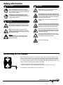
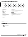
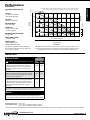
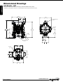
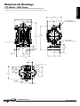
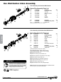
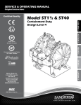
1" 150# A W Original 2.00 Instructions 50.80 2.00 50.80 Certified Quality 4.18 106.29 8.37 212.71 12.03 305.56 3.54 89.81 4X 1.22 30.96 Model G1F Metallic Design Level 1 3.22 81.76 DISCHARGE PORT 1" NPT 3.93 99.89 7.44 AIR INLET 188.98 1/2 NPT Natural Gas-Operated Diaphragm Pumps .38 MOUNTING HOLES 9.53 6.39 162.31 Quality System ISO 9001 Certified ISO 14001 Certified SUCTION PORT 1" NPT 5.31 135 1.63 41.28 4: Gas END .41 10.32 Environmental Management System 4.19 106.43 2: INSTAL & OP SERVICE & OPERATING MANUAL 1: PUMP SPECS 9.09 230.80 3: EXP VIEW 5.13 130.18 5.00 127.00 6.73Certified to CSA Technical Letter No, R-14 171.07 5: WET END BOTTOM VIEW Certified to ANSI LC6-2008 6: OPTIONAL 5.00 127.00 Warren Rupp, Inc. 7: WARRANTY A Unit of IDEX Corporation 800 N. Main St., Mansfield, Ohio 44902 USA Telephone 419.524.8388 Fax 419.522.7867 SANDPIPERPUMP.COM © Copyright 2015 Warren Rupp, Inc. All rights reserved sandpiperpump.com Safety Information IMPORTANT WARNING When used for toxic or aggressive fluids, the pump should always be flushed clean prior to disassembly. Read the safety warnings and instructions in this manual before pump installation and start-up. Failure to comply with the recommendations stated in this manual could damage the pump and void factory warranty. Before maintenance or repair, shut off the compressed air line, bleed the pressure, and disconnect the air line from the pump. Be certain that approved eye protection and protective clothing are worn at all times. Failure to follow these recommendations may result in serious injury or death. When the pump is used for materials that tend to settle out or solidify, the pump should be flushed after each use to prevent damage. In freezing temperatures the pump should be completely drained between uses. Airborne particles and loud noise hazards. Wear eye and ear protection. CAUTION In the event of diaphragm rupture, pumped material may enter the air end of the pump, and be discharged into the atmosphere. If pumping a product that is hazardous or toxic, the air exhaust must be piped to an appropriate area for safe containment. Before pump operation, inspect all fasteners for loosening caused by gasket creep. Retighten loose fasteners to prevent leakage. Follow recommended torques stated in this manual. Take action to prevent static sparking. Fire or explosion can result, especially when handling flammable liquids. The pump, piping, valves, containers and other miscellaneous equipment must be properly grounded. Nonmetallic pumps and plastic components are not UV stabilized. Ultraviolet radiation can damage these parts and negatively affect material properties. Do not expose to UV light for extended periods of time. This pump is pressurized internally with air pressure during operation. Make certain that all fasteners are in good condition and are reinstalled properly during reassembly. WARNING Pump not designed, tested or certified to be powered by compressed natural gas. Powering the pump with natural gas will void the warranty. Use safe practices when lifting kg Grounding ATEX Pumps ATEX compliant pumps are suitable for use in explosive atmospheres when the equipment is properly grounded in accordance with local electrical codes. Pumps equipped with electrically conductive diaphragms are suitable for the transfer of conductive or non-conductive fluids of any explosion group. When operating pumps equipped with non-conductive diaphragms that exceed the maximum permissible projected area, as defined in EN 13461-1: 2009 section 6.7.5 table 9, the following protection methods must be applied: • Equipment is always used to transfer electrically conductive fluids or • Explosive environment is prevented from entering the internal portions of the pump, i.e. dry running For further guidance on ATEX applications, please consult the factory. sandpiperpump . com g1fmdl1sm-rev0915 SECTION 4: GAS END......................................11 • Aluminum Gas Valve Assembly • Stainless Steel Gas Valve Assembly • Pilot Valve Assembly • Intermediate Assembly SECTION 5: WET END......................................14 • Diaphragm Drawings • Diaphragm Servicing • Pumping Hazardous Liquids 2: INSTAL & OP 3: EXP VIEW 7: WARRANTY SECTION 7: WARRANTY & CERTIFICATES.....17 • Warranty • CE Declaration of Conformity - Machinery • ATEX Declaration of Conformity 4: AIR END SECTION 3: EXPLODED VIEW............................8 • Composite Repair Parts Drawing • Composite Repair Parts List • Material Codes 5: WET END SECTION 2: INSTALLATION & OPERATION.......5 • Principle of Pump Operation • Recommended Installation Guide • Troubleshooting Guide 6: OPTIONAL SECTION 1: PUMP SPECIFICATIONS.................1 • Explanation of Nomenclature • Performance • Materials • Dimensional Drawings 1: PUMP SPECS Table of Contents sandpiperpump . com g1fmdl1sm-rev0915 1: PUMP SPECS Explanation of Pump Nomenclature Your Model G #: __ ____ __________________ ____ (fill in from pump nameplate) Pump Brand Model #: Pump Size Check Valve Wetted Diaphragm/ Check Valve Non-Wetted Porting Material Check Valve Seat Material Options Pump Style Muffler Options Pump Brand Pump Size 1F1" Check Valve Type BBall Design Level Design Level Wetted Material S Stainless Steel AAluminum Diaphragm/Check Valve Materials BNitrile/Nitrile T PTFE -Nitrile/PTFE VFKM/FKM 5Nitrile/PTFE Check Valve Seat T Virgin PTFE AAluminum S Stainless Steel Non-Wetted Material Options A Painted Aluminum B Unpainted Aluminum with Stainless Steel Gas Valve D Unpainted Aluminum with Stainless Steel Gas Valve with FKM O-rings X Unpainted Aluminum 0 Unpainted Aluminum/FKM Elastomer V Painted Aluminum/ FKM Elastomer Porting Options NPT Threads BSP (Tapered) Threads 150# Raised Face 1" ANSI Flange w/ Threaded Pipe Connections 150# Welded Raised Face 1" ANSI Flanged Manifolds N B R W Pump Style SStandard Muffler Options X No Muffler Permitted * Your Serial #: (fill in from pump nameplate)______________________________________ ATEX Detail (1) 1 • Model G1F Metallic Pump Options GXXXXXXXXXXXXX G Natural Gas Operated 1 Design Level II 2G c T5 II 2GD T5 II 2D c T100°C sandpiperpump . com g1fmdl1sm-rev0915 Performance G1F Metallic MODEL G1F Metallic Performance Curve HEADS UP TO • 100 psi or 231 ft. of water (7 bar or 70 meters) 3 25(42.5) 80 80 P SI (5 60 MAXIMUM OPERATING PRESSURE • 100 psi (7 bar) DISPLACEMENT/STROKE • .11 Gallon / .42 liter 60 PS ar) SHIPPING WEIGHT • Aluminum 28 lbs. (13kg) • Stainless Steel 43 lbs. (20kg) These pump models are designed to pump the following fluids: Crude Oil, Salt Water, Drilling Mud, Condensate, Lubrication Oils, Glycol, Caustic Liquids, and Acids.” 40(68) 8 Bar) 40 PS I (2.72 20 0 35(59.5) I (4.0 40 0 30(51) .44 B 2 1 1: PUMP SPECS 4 10(17) PSI (6.8 15(25.5) Bar 20(34) ) 20 PSI (1.36 NPSHR SOLIDS-HANDLING • Up to .25 in. (6mm) HEAD 5 100 Bar) Bar) Gas Inl 0 5 0 20 et Pressure 10 40 15 60 20 25 30 U.S. Gallons per minute 80 100 120 Liters per minute 35 40 140 45 160 METERS 6 GAS VALVE • No-lube, no-stall design 5(8.5) 100 FEET 7 CAPACITY • 0 to 45 gallons per minute (0 to 170 liters per minute) Performance based on the following: elastomer fitted pump, flooded suction, water at ambient conditions. The use of other materials and varying hydraulic conditions may result in deviations in excess of 5%. PSI BAR SUCTION/DISCHARGE PORT SIZE • 1" 30 25 20 15 10 5 9.1 7.6 6 4.5 3 1.5 50 180 CAPACITY Exhaust Gas: The exhausted natural gas must be vented to a low pressure safe location in accordance with local fire safety and environmental codes, or in the absence of local codes, an industry or nationally recognized code having jurisdiction over the specific installations, and/or CAN/CGA B149, Installation Codes Materials Material Profile: CAUTION! Operating temperature limitations are as follows: Operating Temperatures: Max. Min. FKM: (Fluorocarbon) Shows good resistance to a wide range of oils and solvents; especially all aliphatic, aromatic and halogenated hydrocarbons, acids, animal and vegetable oils. Hot water or hot aqueous solutions (over 70°F(21°C)) will attack FKM. 350°F 177°C -40°F -40°C Nitrile: General purpose, oil-resistant. Shows good solvent, oil, water and hydraulic fluid resistance. Should not be used with highly polar solvents like acetone and MEK, ozone, chlorinated hydrocarbons and nitro hydrocarbons. 190°F 88°C -10°F -23°C Virgin PTFE: (PFA/TFE) Chemically inert, virtually impervious. Very few chemicals are known to chemically react with PTFE; molten alkali metals, turbulent liquid or gaseous fluorine and a few fluoro-chemicals such as chlorine trifluoride or oxygen difluoride which readily liberate free fluorine at elevated temperatures. 220°F 104°C -35°F -37°C Maximum and Minimum Temperatures are the limits for which these materials can be operated. Temperatures coupled with pressure affect the longevity of diaphragm pump components. Maximum life should not be expected at the extreme limits of the temperature ranges. Metals: Stainless Steel: Equal to or exceeding ASTM specification A743 CF-8M for corrosion resistant iron chromium, iron chromium nickel and nickel based alloy castings for general applications. Commonly referred to as 316 Stainless Steel in the pump industry. For specific applications, always consult the Chemical Resistance Chart. Ambient temperature range: -20°C to +40°C Process temperature range: -20°C to +80°C for models rated as category 1 equipment -20°C to +100°C for models rated as category 2 equipment In addition, the ambient temperature range and the process temperature range do not exceed the operating temperature range of the applied non-metallic parts as listed in the manuals of the pumps. sandpiperpump . com g1fmdl1sm-rev0915 Model G1F Metallic • 2 1: PUMP SPECS Dimensional Drawings G1F Metallic - NPT Dimensions in inches (mm dimensions in brackets). Dimensional Tolerance:±1/8" (± 3mm) The dimensions on this drawing are for reference only. A certified drawing can be requested if physical dimensions are needed. 10.25 260.35 10.25 260.35 9.09 230.80 9.09 230.80 5.13 130.18 5.13 130.18 12.88 327.09 12.88 327.09 AIR INLET 1/2 NPT AIR INLET 1/2 NPT 12.03 305.56 12.03 305.56 6.40 162.43 6.40 162.43 .41 10.32 .41 10.32 SUCTION PORT 1" NPT EXHAUST PORT 1" NPT SUCTION PORT 1" NPT 4X R.16 3.97 4X R.16 3.97 6.39 162.31 6.39 162.31 1.22 30.96 1.22 30.96 1" NPT EXHAUST PORT 1.63 41.28 1.63 41.28 5.00 127.00 5.00 127.00 6.75 171.45 6.75 171.45 3.87 98.35 3.87 98.35 5.00 127.00 5.00 127.00 8.16 207.19 8.16 207.19 BOTTOM VIEW BOTTOM VIEW 3 • Model G1F Metallic DISCHARGE PORT 1" NPT DISCHARGE PORT 1" NPT sandpiperpump . com g1fmdl1sm-rev0915 Dimensional Drawings G1F Metallic - ANSI Flange 1: PUMP SPECS Dimensions in inches (mm dimensions in brackets). Dimensional Tolerance:±1/8" (± 3mm) The dimensions on this drawing are for reference only. A certified drawing can be requested if physical dimensions are needed. 9.10 231.14 10.25 260.35 10.25 260.35 5.13 130.18 3.87 98.17 5.13 10.25 130.18 260.35 9.10 231.14 4.64 DISCHARGE PORT DISCHARGE PORT 117.73 4.64 3.87 117.73 98.17 1" 150# ANSI RF1"FLANGE 150# ANSI RF FLA 3.87 98.17 5.13 130.18 16.04 407.30 9.10 231.14 14.04 356.50 16.04 407.30 4.64 117.73 DISCHAR 1" 150# AN 14.04 356.50 14.04 356.50 16.04 407.30 SUCTION PORTSUCTION PORT 1" 150# ANSI RF1"FLANGE 150# ANSI RF FLA EXHAUST PORT 1" NPT EXHAUST PORT SUCTION 1" 150# AN 1" NPT EXHAUST PORT 2.00 50.80 2.00 50.80 .13 3.18 .13 3.18 4.18 106.29 3.22 81.76 3.93 99.89 2.00 50.80 8.37 212.71 4.18 106.29 7.44 188.98 8.37 3.54 212.71 89.81 3.54 89.81 3.22 81.76 2.00 50.80 2.00 50.80 4.18 106.29 .138.37 212.71 3.18 3.22 81.76 2.00 50.80 3.93 99.89 3.93 99.89 7.44 188.98 7.44 188.98 3.54 4X 3.22 81.76 2.09 53.18 3.22 81.76 7.44 188.98 89.81 4X HOLES .38 MOUNTING .38 MOUNTING HOLES 9.53 9.53 4X 2.09 53.18 3.22 81.76 4.19 106.43 2.09 53.18 5.31 135 4.19 106.43 AIR INLET 1/2" NPT 6.73 171.07 5.31 135 4.19 106.43 7.44 188.98 AIR INLET 1/2" NPT .38 MOUNTING HOLES 9.53 5.31 135 6.73 171.07 AIR INLET BOTTOM VIEW BOTTOM VIEW 1/2" NPT 6.73 171.07 sandpiperpump . com g1fmdl1sm-rev0915 BOTTOM VIEW Model G1F Metallic • 4 Principle of Pump Operation 2: INSTAL & OP Gas-Operated Double Diaphragm pumps are powered by compressed gas, nitrogen or natural gas. The main directional (gas) control valve ① distributes compressed gas to an gas chamber, exerting uniform pressure over the inner surface of the diaphragm ②. At the same time, the exhausting gas ③ from behind the opposite diaphragm is directed through the gas valve assembly(s) to an exhaust port ④. Gas Line As inner chamber pressure (P1) exceeds liquid chamber pressure (P2), the rod ⑤ connected diaphragms shift together creating discharge on one side and suction on the opposite side. The discharged and primed liquid’s directions are controlled by the check valves (ball or flap)⑥ orientation. Discharged Fluid Discharge Stroke Suction Stroke The pump primes as a result of the suction stroke. The suction stroke lowers the chamber pressure (P3) increasing the chamber volume. This results in a pressure differential necessary for atmospheric pressure (P4) to push the fluid through the suction piping and across the suction side check valve and intoAREA the outer fluid chamber ⑦. PUMP INSTALLATION SAFE AIR EXHAUST DISPOSAL Suction (side) stroking also initiates the reciprocating AREA (shifting, stroking or cycling) action of the pump. The suction 1" DIAMETER AIR diaphragm’s movement is mechanically pulled through its EXHAUST PIPING stroke. The diaphragm’s inner plate makes contact with an MUFFLER actuator plunger aligned to shift the pilot signaling valve. Once actuated, the pilot valve sends a pressure signal to the opposite end of the main directional gas valve, redirecting the compressed gas to the opposite inner chamber. Primed Fluid SUBMERGED ILLUSTRATION MUFFLER 1" DIAMETER AIR EXHAUST PIPING LIQUID LEVEL SUCTION LINE Pump can be submerged if the pump materials of construction are compatible with the liquid being pumped. The gas exhaust must be piped above the liquid level. When the MUFFLER pumped product source is at a higher level than the pump (flooded suction condition), pipe the exhaust higher than the product source to prevent siphoning spills. 1" DIAMETER AIR EXHAUST PIPING LIQUID LEVEL 5 • Model G1F Metallic SUCTION LINE sandpiperpump . com g1fmdl1sm-rev0915 Recommended Installation Guide 1 020.063.000 Filter VENTING WARNING: This filter is equipped with a stainless steel manual drain. The port is 1/8" NPT. When draining moisture from the filter, first shut off the natural gas supply. 2 020.058.000 REGULATOR WITH GAGE PRESSURE WARNING: This regulator is to be installed at point of use with the pump. The maximum gas supply is 400psi. Full line pressure needs to be regulated below 400psi prior to the regulator installation position. VENTING WARNING: This regulator is equipped with a 1/4" NPT vent port. In the event of a diaphragm rupture, natural gas can be exhausted into the surrounding environment. Connect a conductive hose or pipe to the vent port to send the escaping natural gas to a safe area for gas reclamation. Make sure to ground the regulator, hose, and/or pipe. CAUTION The gas exhaust should be p iped to an area for safe d isposition of the product b eing pumped, in the event of a diaphragm failure. Available from Warren Rupp Flexible Conductive Connection Pipe Connection (Style Optional) Natural Gas Exhaust Gas Shut-Off Valve Regulator w/Gauge Filter Gauge Shut-Off Valve 2: INSTAL & OP Top Discharge Ball Valve Pump Natural gas supply conductive piping must be supported Natural Gas Inlet 1 Flexible Connection SUCTION 2 Drain Port The pump must be rigidly mounted in the horizontal position with fasteners to a conductive base or natural ground. Installation And Start-Up Locate the pump as close to the product being pumped as possible. Keep the suction line length and number of fittings to a minimum. Do not reduce the suction line diameter. Gas Supply Connect the pump gas inlet to an gas supply with sufficient capacity and pressure to achieve desired performance. A pressure regulating valve should be installed to insure gas supply pressure does not exceed recommended limits. Gas Valve Lubrication The gas distribution system is designed to operate WITHOUT lubrication. This is the standard mode of operation. If lubrication is desired, install an gas line lubricator set to deliver one drop of SAE 10 non-detergent oil for every 20 SCFM (9.4 liters/sec.) of gas the pump consumes. Consult the Performance Curve to determine gas consumption. Gas Line Moisture Water in the compressed gas supply may cause icing or freezing of the exhaust gas, causing the pump to cycle erratically or stop operating. Water in the gas supply can be reduced by using a point-of-use gas dryer. Gas Inlet And Priming To start the pump, slightly open the gas shut-off valve. After the pump primes, the gas valve can be opened to increase gas flow as desired. If opening the valve increases cycling rate, but does not increase the rate of flow, cavitation has occurred. The valve should be closed slightly to obtain the most efficient gas flow to pump flow ratio. sandpiperpump . com g1fmdl1sm-rev0915 Model G1F Metallic • 6 Troubleshooting Guide Symptom: Pump Cycles Once 2: INSTAL & OP Pump Will Not Operate / Cycle Pump Cycles and Will Not Prime or No Flow Pump Cycles Running Sluggish / Stalling, Flow Unsatisfactory Product Leaking Through Exhaust Premature Diaphragm Failure Unbalanced Cycling Potential Cause(s): Deadhead (system pressure meets or exceeds gas supply pressure). Gas valve or intermediate gaskets installed incorrectly. Bent or missing actuator plunger. Pump is over lubricated. Lack of gas (line size, PSI, CFM). Check gas distribution system. Discharge line is blocked or clogged manifolds. Deadhead (system pressure meets or exceeds gas supply pressure). Blocked gas exhaust muffler. Pumped fluid in gas exhaust muffler. Pump chamber is blocked. Cavitation on suction side. Check valve obstructed. Valve ball(s) not seating properly or sticking. Recommendation(s): Increase the inlet gas pressure to the pump. Pump is designed for 1:1 pressure ratio at zero flow. (Does not apply to high pressure 2:1 units). Install gaskets with holes properly aligned. Remove pilot valve and inspect actuator plungers. Set lubricator on lowest possible setting or remove. Units are designed for lube free operation. Check the gas line size and length, compressor capacity (HP vs. cfm required). Disassemble and inspect main gas distribution valve, pilot valve and pilot valve actuators. Check for inadvertently closed discharge line valves. Clean discharge manifolds/piping. Increase the inlet gas pressure to the pump. Pump is designed for 1:1 pressure ratio at zero flow. (Does not apply to high pressure 2:1 units). Remove muffler screen, clean or de-ice, and re-install. Disassemble pump chambers. Inspect for diaphragm rupture or loose diaphragm plate assembly. Disassemble and inspect wetted chambers. Remove or flush any obstructions. Check suction condition (move pump closer to product). Disassemble the wet end of the pump and manually dislodge obstruction in the check valve pocket. Clean out around valve ball cage and valve seat area. Replace valve ball or valve seat if damaged. Use heavier valve ball material. Valve ball(s) missing (pushed into chamber or Worn valve ball or valve seat. Worn fingers in valve ball cage (replace part). Check Chemical manifold). Resistance Guide for compatibility. Valve ball(s) / seat(s) damaged or attacked by product. Check Chemical Resistance Guide for compatibility. Check valve and/or seat is worn or needs adjusting. Inspect check valves and seats for wear and proper setting. Replace if necessary. Suction line is blocked. Remove or flush obstruction. Check and clear all suction screens or strainers. Excessive suction lift. For lifts exceeding 20’ of liquid, filling the chambers with liquid will prime the pump in most cases. Suction side gas leakage or gas in product. Visually inspect all suction-side gaskets and pipe connections. Pumped fluid in gas exhaust muffler. Disassemble pump chambers. Inspect for diaphragm rupture or loose diaphragm plate assembly. Over lubrication. Set lubricator on lowest possible setting or remove. Units are designed for lube free operation. Icing. Remove muffler screen, de-ice, and re-install. Install a point of use gas drier. Clogged manifolds. Clean manifolds to allow proper gas flow. Deadhead (system pressure meets or exceeds gas Increase the inlet gas pressure to the pump. Pump is designed for 1:1 pressure ratio at zero flow. supply pressure). (Does not apply to high pressure 2:1 units). Cavitation on suction side. Check suction (move pump closer to product). Lack of gas (line size, PSI, CFM). Check the gas line size, length, compressor capacity. Excessive suction lift. For lifts exceeding 20’ of liquid, filling the chambers with liquid will prime the pump in most cases. Gas supply pressure or volume exceeds system hd. Decrease inlet gas (press. and vol.) to the pump. Pump is cavitating the fluid by fast cycling. Undersized suction line. Meet or exceed pump connections. Restrictive or undersized gas line. Install a larger gas line and connection. Suction side gas leakage or gas in product. Visually inspect all suction-side gaskets and pipe connections. Suction line is blocked. Remove or flush obstruction. Check and clear all suction screens or strainers. Pumped fluid in gas exhaust muffler. Disassemble pump chambers. Inspect for diaphragm rupture or loose diaphragm plate assembly. Check valve obstructed. Disassemble the wet end of the pump and manually dislodge obstruction in the check valve pocket. Check valve and/or seat is worn or needs adjusting. Inspect check valves and seats for wear and proper setting. Replace if necessary. Entrained gas or vapor lock in chamber(s). Purge chambers through tapped chamber vent plugs. Purging the chambers of gas can be dangerous. Diaphragm failure, or diaphragm plates loose. Replace diaphragms, check for damage and ensure diaphragm plates are tight. Diaphragm stretched around center hole or bolt holes. Check for excessive inlet pressure or gas pressure. Consult Chemical Resistance Chart for compatibility with products, cleaners, temperature limitations and lubrication. Cavitation. Enlarge pipe diameter on suction side of pump. Excessive flooded suction pressure. Move pump closer to product. Raise pump/place pump on top of tank to reduce inlet pressure. Install Back pressure device (Tech bulletin 41r). Add accumulation tank or pulsation dampener. Misapplication (chemical/physical incompatibility). Consult Chemical Resistance Chart for compatibility with products, cleaners, temperature limitations and lubrication. Incorrect diaphragm plates or plates on backwards, Check Operating Manual to check for correct part and installation. Ensure outer plates have not been installed incorrectly or worn. worn to a sharp edge. Excessive suction lift. For lifts exceeding 20’ of liquid, filling the chambers with liquid will prime the pump in most cases. Undersized suction line. Meet or exceed pump connections. Pumped fluid in gas exhaust muffler. Disassemble pump chambers. Inspect for diaphragm rupture or loose diaphragm plate assembly. Suction side gas leakage or gas in product. Visually inspect all suction-side gaskets and pipe connections. Check valve obstructed. Disassemble the wet end of the pump and manually dislodge obstruction in the check valve pocket. Check valve and/or seat is worn or needs adjusting. Inspect check valves and seats for wear and proper setting. Replace if necessary. Entrained gas or vapor lock in chamber(s). Purge chambers through tapped chamber vent plugs. For additional troubleshooting tips contact After Sales Support at [email protected] or 419-524-8388 7 • Model G1F Metallic sandpiperpump . com g1fmdl1sm-rev0915 Composite Repair Parts Drawing Torque: 90 in/lbs 8 18 11 4 32 17 ATTACH EYELET TO ONE OF THE FOUR CAPSCREWS ITEM # 11 31 Torque: 90 in/lbs 25 7 21 12 20 9 26 30 28 16 1 5 3: EXP VIEW 2 3 29 27 13 6 10 23 14 14 15 24 Torque: 350 in/lbs 2 24 29 Torque: 450 in/lbs 22 OPTIONAL OVERLAY 19 30 30 9 Service & Repair Kits 476.228.000 Gas End Kit Seals, O-Rings, Gaskets, Retaining Rings, Valve Assembly and Pilot Valve Assembly 476.228.363 Gas End Kit FKM Seals, O-Rings, Gaskets, Retaining Rings, Valve Assembly and Pilot Valve Assembly 476.204.360 Wetted End Kit Nitrile Diaphagms, Nitrle Check Balls and PTFE Check Valve Seats 476.204.649 Wetted End Kit Nitrile Diaphragms, PTFE Overlay Diaphragms, PTFE Check Balls and PTFE Check Valve Seats 22 OPTIONAL METALLIC SEAT 476.319.000 Gas End Wear Kit Nitrile 0-rings, Bumpers and Seals 476.319.363 Gas End Wear Kit FKM 0-rings, Bumpers, and Seals 474.008.360 Wet End Wear Kit Nitrile Diaphagms 474.015.604 Wet End Wear Kit Nitrile Backer Diaphragms PTFE Overlay Diaphragms 476.204.672 Wetted End Kit Nitrile Diaphragms, PTFE Check Balls and PTFE Check Valve Seats sandpiperpump . com g1fmdl1sm-rev0915 Model G1F Metallic • 8 3: EXP VIEW Composite Repair Parts List Item Part Number Description 1 031-179-000 Stainless Steel Gas Valve Assembly (use with Option B) Stainless Steel Gas Valve Assembly 031-179-363 Qty 1 Item Part Number Description 21 560-001-363 O-Ring Qty 2 560-001-360 O-Ring 2 22 560-091-360 O-Ring (metallic seats only) 8 with FKM O-rings (used with Option D) 1 560-091-611 O-Ring (metallic seats only) 8 031-183-000 Gas Valve Assembly 1 23 612-022-330 Plate, Inner Diaphragm 2 031-183-363 Gas Valve Assembly 1 24 612-108-157 Plate, Outer Diaphragm Assembly 2 2 050-028-360 Ball, Check 4 612-101-110 Plate, Outer Diaphragm Assembly 2 050-028-600 Ball, Check 4 25 620-022-115 Pin, Actuator 2 3 070-012-170 Bushing 2 26 675-042-115 Ring, Retaining 2 4 095-110-000 Pilot Valve Assembly 1 27 685-060-120 Rod, Diaphragm 1 095-110-363 Pilot Valve Assembly with FKM O-rings 1 28 720-010-363 Seal, U-Cup 2 5 114-025-157 Intermediate Bracket 1 720-010-375 Seal, U-Cup 2 6 132-019-360 Bumper, Diaphragm 2 29 722-098-600 Seat, Check Valve 4 132-019-363 Bumper, Diaphragm 2 722-098-110 Seat, Check Valve 4 7 135-036-506 Bushing, Plunger 2 722-098-150 Seat, Check Valve 4 8 165-120-000 Cap, Gas Inlet Assembly 1 30 900-004-330 Washer, Lock, 5/16 16 9 170-044-330 Capscrew, Hex Hd 5/16-18 X .1.00 16 31 901-038-330 Flat, Washer 4 10 170-045-330 Capscrew, Hex Hd 5/16-18 X 1.25 16 32 920-025-000 Ground Strap 1 11 170-069-330 Capscrew, Hex Hd 5/16-18 X 1.75 4 12 170-006-330 Capscrew, Hex 3/8-16 X 1.00 4 Parts not shown used with Raised Face ANSI Flange Options R and W: 13 196-173-157 Chamber, Outer 2 170.043.330 Hex Cap Screw 4 196-173-110 Chamber, Outer 2 326.050.080 Mounting Foot 2 14 286-008-360 Diaphragm 2 545.003.330 Hex Nut 4 15 286-015-604 Diaphragm, Overlay 2 900.001.330 Lock Washer 4 16 360-093-360 Gasket, Natural Gas Valve 1 901.002.330 Flat Washer 8 17 360-114-360 Gasket, Pilot Valve 1 18 360-104-379 Gasket, Gas Inlet 1 Parts not shown used with Raised Face ANSI Flange Option R ONLY: 19 518-175-156 Manifold, Suction 1 518-175-156E Manifold, Suction 1"BSP (Tapered) 1 518-175-156W Welded Raised Face 150# 1" ANSI Flanged Manifold 1 518-175-110 Manifold, Suction 1 518-175-110E Manifold, Suction 1"BSP (Tapered) 1 518-175-110W Welded Raised Face 150# 1" ANSI Flanged Manifold 1 20 518-176-156 Manifold, Discharge 1 518-176-156E Manifold, Discharge 1"BSP (Tapered) 1 518-176-156W Welded Raised Face 150# 1" ANSI Flanged Manifold 1 518-176-110 Manifold, Discharge 1 518-176-110E Manifold, Discharge 1"BSP (Tapered) 1 518-176-110W Welded Raised Face 150# 9 • Model G1F Metallic 1" ANSI Flanged Manifold 1 334.112.110 538.035.110 1" ANSI 150# Raised Face Flange and Threaded Pipe Connection 2 1" NPT Pipe Nipple x 1 1/2 Long 2 LEGEND: = Items contained within Gas End Kits = Items contianed within Wet End Kits Note: Kits contain components specific to the material codes. ATEX Compliant sandpiperpump . com g1fmdl1sm-rev0915 000����Assembly, sub-assembly; and some purchased items 010����Cast Iron 015����Ductile Iron 020����Ferritic Malleable Iron 080����Carbon Steel, AISI B-1112 110�����Alloy Type 316 Stainless Steel 111�����Alloy Type 316 Stainless Steel (Electro Polished) 112�����Alloy C 113�����Alloy Type 316 Stainless Steel (Hand Polished) 114�����303 Stainless Steel 115�����302/304 Stainless Steel 117�����440-C Stainless Steel (Martensitic) 120����416 Stainless Steel (Wrought Martensitic) 148����Hardcoat Anodized Aluminum 150����6061-T6 Aluminum 152����2024-T4 Aluminum (2023-T351) 155����356-T6 Aluminum 156����356-T6 Aluminum 157����Die Cast Aluminum Alloy #380 158����Aluminum Alloy SR-319 162����Brass, Yellow, Screw Machine Stock 165����Cast Bronze, 85-5-5-5 166����Bronze, SAE 660 170����Bronze, Bearing Type, Oil Impregnated 180����Copper Alloy 305����Carbon Steel, Black Epoxy Coated 306����Carbon Steel, Black PTFE Coated 307����Aluminum, Black Epoxy Coated 308����Stainless Steel, Black PTFE Coated 309����Aluminum, Black PTFE Coated 313����Aluminum, White Epoxy Coated 330����Zinc Plated Steel 332����Aluminum, Electroless Nickel Plated 333����Carbon Steel, Electroless Nickel Plated 335����Galvanized Steel 337����Silver Plated Steel 351����Food Grade Santoprene® 353����Geolast; Color: Black 354����Injection Molded #203-40 Santoprene® Duro 40D +/-5; Color: RED 356����Hytrel® 357����Injection Molded Polyurethane 358����Urethane Rubber (Some Applications) (Compression Mold) 359����Urethane Rubber 360����Nitrile Rubber Color coded: RED 363����FKM (Fluorocarbon) Color coded: YELLOW The Last 3 Digits of Part Number 364����EPDM Rubber Color coded: BLUE 365����Neoprene Rubber Color coded: GREEN 366����Food Grade Nitrile 368����Food Grade EPDM 371����Philthane (Tuftane) 374����Carboxylated Nitrile 375����Fluorinated Nitrile 378����High Density Polypropylene 379����Conductive Nitrile 408����Cork and Neoprene 425����Compressed Fibre 426����Blue Gard 440����Vegetable Fibre 500����Delrin® 500 502����Conductive Acetal, ESD-800 503����Conductive Acetal, Glass-Filled 506����Delrin® 150 520����Injection Molded PVDF Natural color 540����Nylon 542����Nylon 544����Nylon Injection Molded 550����Polyethylene 551����Glass Filled Polypropylene 552����Unfilled Polypropylene 555����Polyvinyl Chloride 556����Black Vinyl 558����Conductive HDPE 570����Rulon II® 580����Ryton® 600����PTFE (virgin material) Tetrafluorocarbon (TFE) 603����Blue Gylon® 604����PTFE 606����PTFE 607����Envelon 608����Conductive PTFE 610����PTFE Encapsulated Silicon 611�����PTFE Encapsulated FKM 632����Neoprene/Hytrel® 633����FKM/PTFE 634����EPDM/PTFE 635����Neoprene/PTFE 637����PTFE, FKM/PTFE 638����PTFE, Hytrel®/PTFE 639����Nitrile/TFE 643����Santoprene®/EPDM 644����Santoprene®/PTFE 656�����Santoprene® Diaphragm and Check Balls/EPDM Seats 661����EPDM/Santoprene® 666����FDA Nitrile Diaphragm, PTFE Overlay, Balls, and Seals 668����PTFE, FDA Santoprene®/PTFE sandpiperpump . com g1fmdl1sm-rev0915 • Delrin and Hytrel are registered tradenames of E.I. DuPont. • Nylatron is a registered tradename of Polymer Corp. • Gylon is a registered tradename of Garlock, Inc. • Santoprene is a registered tradename of Exxon Mobil Corp. • Rulon II is a registered tradename of Dixion Industries Corp. • Ryton is a registered tradename of Phillips Chemical Co. • Valox is a registered tradename of General Electric Co. 3: EXP VIEW Material Codes - R E C YC L I N G Many components of SANDPIPER® AODD pumps are made of recyclable materials. We encourage pump users to recycle worn out parts and pumps whenever possible, after any hazardous pumped fluids are thoroughly flushed. Model G1F Metallic • 10 Gas Distribution Valve Assembly 1-F 1-E Valve Assembly for Aluminum Mid Sections Natural Gas Assembly Parts List 1-D 1-D Item 1 1-A 1-B 1-C 1-D 1-E 1-F 1-C 1-B 1-B Part Number 031-183-000 095-109-157 031-139-000 132-029-357 560-020-360 165-127-157 170-032-330 Description Qty Gas Valve Assembly 1 Valve Body 1 Sleeve and Spool Set 1 Bumper 2 O-Ring 10 Cap, End 2 Capscrew 8 1-E Item Part Number Description Qty 1 031-183-363 Gas Valve Assembly (FKM) 1 1-D 560-020-363 O-Ring (FKM) 10 (includes all other items used on 031.183.000) 1-A 1-C 1-D 1-F Valve Assembly for Stainless Steel Mid Sections 1-F 4: AIR END 1-D 1-D 1-C 1-B 1-B 1-A 1-C 1-D 1-F 1-E 1-E Natural Gas Assembly Parts List Item 1 1-A 1-B 1-C 1-D 1-E 1-F Part Number 031-179-000 095-109-110 031-139-000 132-029-357 560-020-360 165-127-110 170-032-115 170-032-110 Description Qty Gas Valve Assembly 1 Valve Body 1 Sleeve and Spool Set 1 Bumper 2 O-Ring 10 Cap, End 2 Capscrew 8 3/16" Stainless Steel Option 8 Part Number Description Qty Item 1 031-179-363 Gas Valve Assembly (FKM) 1 1-D 560-020-363 O-Ring (FKM) 10 (includes all other items used on 031.179.000) Gas Distribution Valve Servicing Step 1: Remove cap screws (1-F). Step 2: Remove end cap (1-E) and bumper (1-C). Step 3: Remove spool part of (1-B) (caution: do not scratch). Step 4: Press sleeve (1-B) from body (1-A). Step 5: Inspect O-Ring (1-C) and replace if necessary. IMPORTANT Read these instructions completely, before installation and start-up. It is the responsibility of the purchaser to retain this manual for reference. Failure to comply with the recommendations stated in this manual will damage the pump, and void factory warranty. Step 6: Lightly lubricate O-Rings (1-C) on spool (1-B). Step 7: Press sleeve (1-B) into body (1-A). Step 8: Reassemble in reverse order, starting with step 3. Note: Sleeve and spool (1-B) set is match ground to a specified clearance sleeve and spools (1-B) cannot be interchanged. ATEX Compliant 11 • Model G1F Metallic sandpiperpump . com g1fmdl1sm-rev0915 Pilot Valve Servicing With Pilot Valve removed from pump. Step 1: Remove snap ring (4-F). Step 2: Remove sleeve (4-B), inspect O-Rings (4-C), replace if required. Step 3: Remove spool (4-D) from sleeve (4-B), inspect O-Rings (4-E), replace if required. Step 4: Lightly lubricate O-Rings (4-C) and (4-E). Reassemble in reverse order. Pilot Valve Assembly Parts List Item 4 4-A 4-B 4-C 4-D 4-E 4-F Part Number 095-110-000 095-095-157 755-052-000 560-033-360 775-055-000 560-023-360 675-037-080 Description Pilot Valve Assembly Valve Body Sleeve (With O-Rings) O-Ring (Sleeve) Spool (With O-Rings) O-Ring (Spool) Retaining Ring Item Part Number Description Pilot Valve Assembly 4 095-110-363 4-B 755-052-363 Sleeve (With O-Rings) (FKM) 4-C 560-033-363 O-Ring (Sleeve) (FKM) 4-D 775.055.363 Spool (With O-Rings) (FKM) 4-E 560-023-363 O-Ring (Spool) (FKM) (includes all other items used on 095-110-000) Qty 1 1 1 6 1 3 1 4: AIR END Pilot Valve Assembly Qty 1 1 6 1 3 sandpiperpump . com g1fmdl1sm-rev0915 Model G1F Metallic • 12 Intermediate Assembly 4: AIR END 28 Intermediate Assembly Drawing Step 1: Remove plunger, actuator (25) from center of intermediate pilot valve cavity. Step 2: Remove Ring, Retaining (26), discard. Step 3: Remove bushing, plunger (7), inspect for wear and replace if necessary with genuine parts. Step 4: Remove O-Ring (21), inspect for wear and replace if necessary with genuine parts. Step 5: Lightly lubricate O-Ring (21) and insert into Intermediate Assembly Parts List Item 5 7 21 25 26 28 Part Number 114-025-157 135-036-506 560-001-360 560-001-363 620-022-115 675-042-115 720-010-375 720-010-363 Description Intermediate Bushing, Plunger* O-Ring O-Ring (FKM) Plunger, Actuator* Ring, Retaining Seal, Diaphragm Rod* Seal, Diaphragm Rod* (FKM) intermediate. Step 6: Utilizing a new Ring, Retaining (26) reassemble in reverse order Step 7: Remove Seal, Diaphragm Rod (28). Step 8: Clean seal area, lightly lubricate and install new Seal, Diaphragm Rod (28). IMPORTANT When the pumped product source is at a higher level than the pump (flooded suction condition), pipe the exhaust higher than the product source to prevent siphoning spills. In the event of a diaphragm failure a complete rebuild of the center section is recommended. 13 • Model G1F Metallic sandpiperpump . com g1fmdl1sm-rev0915 Qty 1 2 2 2 2 2 2 2 Diaphragm Service Drawing, with Overlay Torque: 450 in/lbs Torque: 350 in/lbs sandpiperpump . com g1fmdl1sm-rev0915 5: WET END Diaphragm Service Drawing, Non-Overlay Model G1F Metallic • 14 Diaphragm Servicing Step 1: With manifolds and outer chambers removed, remove diaphragm assemblies from diaphragm rod. DO NOT use a pipe wrench or similar tool to remove assembly from rod. Flaws in the rod surface may damage bearings and seal. Soft jaws in a vise are recommended to prevent diaphragm rod damage. Step 1.A: NOTE: Not all inner diaphragm plates are threaded. Some models utilize a through hole in the inner diaphragm plate. If required to separate diaphragm assembly, place assembly in a vise, gripping on the exterior cast diameter of the inner plate. Turn the outer plate clockwise to separate the assembly. Always inspect diaphragms for wear cracks or chemical attack. Inspect inner and outer plates for deformities, rust scale and wear. Inspect intermediate bearings for elongation and wear. Inspect diaphragm rod for wear or marks. Clean or repair if appropriate. Replace as required. Step 2: Reassembly: There are two different types of diaphragm plate assemblies utilized throughout the Sandpiper product line: Outer plate with a threaded stud, diaphragm, and a threaded inner plate. 5: WET END Outer plate with a threaded stud, diaphragm, and an inner plate with through hole. Secure threaded inner plate in a vise. Ensure that the plates are being installed with the outer radius against the diaphragm. Step 3: Lightly lubricate, with a compatible material, the inner faces of both outer and inner diaphragm plates when using on non Overlay diaphragms (For EPDM water is recommended). No lubrication is required. Step 4: Push the threaded outer diaphragm plate through the center hole of the diaphragm. Note: Most diaphragms are installed with the natural bulge out towards the fluid side. S05, S07, and S10 non–metallic units are installed with the natural bulge in towards the gas side. Step 5: Thread or place, outer plate stud into the inner plate. For threaded inner plates, use a torque wrench to tighten the assembly together. Torque values are called out on the exploded view. Repeat procedure for second side assembly. Allow a minimum of 15 minutes to elapse after torquing, then re-torque the assembly to compensate for stress relaxation in the clamped assembly. Step 6: Thread one assembly onto the diaphragm rod with sealing washer (when used) and bumper. Step 7: Install diaphragm rod assembly into pump and secure by installing the outer chamber in place and tightening the capscrews. Step 8: On opposite side of pump, thread the remaining assembly onto the diaphragm rod. Using a torque wrench, tighten the assembly to the diaphragm rod. Align diaphragm through bolt holes, always going forward past the recommended torque. Torque values are called out on the exploded view. NEVER reverse to align holes, if alignment cannot be achieved without damage to diaphragm, loosen complete assemblies, rotate diaphragm and reassemble as described above. IMPORTANT Read these instructions completely, before installation and start-up. It is the responsibility of the purchaser to retain this manual for reference. Failure to comply with the recommendations stated in this manual will damage the pump, and void factory warranty. 15 • Model G1F Metallic sandpiperpump . com g1fmdl1sm-rev0915 PUMPING HAZARDOUS LIQUIDS When a diaphragm fails, the pumped liquid or fumes enter the natural gas end of the pump. Fumes are exhausted into the surrounding environment. When pumping hazardous or toxic materials, the exhaust gas must be piped to an appropriate area for safe disposal. See illustration #1 at right. This pump can be submerged if the pump materials of construction are compatible with the liquid being pumped. The natural gas exhaust must be piped above the liquid level. See illustration #2 at right. Piping used for the gas exhaust must not be smaller than 1" (2.54 cm) diameter. Reducing the pipe size will restrict natural gas flow and reduce pump performance. When the pumped product source is at a higher level than the pump (flooded suction condition), pipe the exhaust gas higher than the product source to prevent siphoning spills. See illustration #3 at right. NATURAL GAS EXHAUST ILLUSTRATION PUMP INSTALLATION AREA SAFE AIR EXHAUST DISPOSAL AREA 1" DIAMETER AIR EXHAUST PIPING MUFFLER Illustration #1 PIPING THE NATURAL GAS EXHAUST The following steps are necessary to pipe the exhaust gas away from the pump.The gas distribution valve assembly (item 1) has 1" NPT threads for piped exhaust. IMPORTANT INSTALLATION NOTE: The manufacturer recommends installing a flexible conductive hose or connection between the pump and any rigid plumbing. This reduces stresses on the molded threads of the natural gas exhaust port. Failure to do so may result in damage to the natural gas distribution valve body. Any piping or hose connected to the pump’s natural gas exhaust port must be conductive and physically supported. Failure to support these connections could also result in damage to the valve body. If a high pressure gas spike is possible through the exhaust line, a pressure regulator is required in the exhaust piping. MUFFLER 1" DIAMETER AIR EXHAUST PIPING LIQUID LEVEL SUCTION LINE Illustration #2 MUFFLER SUCTION LINE Illustration #3 5: WET END 1" DIAMETER AIR EXHAUST PIPING LIQUID LEVEL WARNING Natural gas exhaust is to be vented to low pressure safe location using conductive Nitrile rubber hose or metal piping in accordance with local fire and environmental codes, or an industry or nationally recognized code having jurisdiction over specific installations, and/or CAN/CGA B149, Installation Codes. sandpiperpump . com g1fmdl1sm-rev0915 Model G1F Metallic • 16 Written Warranty 5 - YEAR Limited Product Warranty Quality System ISO 9001 Certified • Environmental Management Systems ISO 14001 Certified Warren Rupp, Inc. (“Warren Rupp”) warrants to the original end-use purchaser that no product sold by Warren Rupp that bears a Warren Rupp brand shall fail under normal use and service due to a defect in material or workmanship within five years from the date of shipment from Warren Rupp’s factory. Warren Rupp brands include SANDPIPER®, MARATHON®, PortaPump®, SludgeMaster™ and Tranquilizer®. ~ See complete warranty at sandpiperpump.com/content/warranty-certifications ~ Declaration of Conformity 7: WARRANTY Manufacturer: Warren Rupp, Inc.®, 800 N. Main Street Mansfield, Ohio, 44902 USA Certifies that Air-Operated Double Diaphragm Pump Series: HDB, HDF, M Non-Metallic, S Non-Metallic, M Metallic, S Metallic, T Series, G Series, U Series, EH and SH High Pressure, RS Series, W Series, SMA and SPA Submersibles, and Tranquilizer® Surge Suppressors comply with the European Community Directive 2006/42/EC on Machinery, according to Annex VIII. This product has used Harmonized Standard EN809:1998+A1:2009, Pumps and Pump Units for Liquids - Common Safety Requirements, to verify conformance. Signature of authorized person October 20, 2005 Date of issue David Roseberry Printed name of authorized person Engineering Manager Title Revision Level: F August 23, 2012 Date of revision EC Declaration of Conformity In accordance with ATEX Directive 94/9/EC, Equipment intended for use in potentially explosive environments. Manufacturer: Warren Rupp, Inc.® A Unit of IDEX Corportion 800 North Main Street P.O. Box 1568 Mansfield, OH 44902 USA Applicable Standard: EN13463-1: 2001 EN13463-5: 2003 EN60079-25: 2004 Harmonised Standard: EN13463-1: 2009 EN13463-5: 2011 EN60079-25:2010 The harmonised standards have been compared to the applicable standards used for certification purposes and no changes in the state of the art technical knowledge apply to the listed equipment. AODD Pumps and Surge Suppressors Directive: 94/9/EC, Annex VIII Technical File No.: 203104000-1410/MER AODD (Air-Operated Double Diaphragm) Pumps EC Type Examination Certificate No. Pumps: KEMA 09ATEX0071 X DATE/APPROVAL/TITLE: 2 July 2015 David Roseberry, Director of Engineering WR_DofC_ATEX_V_rev0815 7: WARRANTY DEKRA Certification B.V. (0344) Meander 1051 6825 MJ Arnhem The Netherlands