1
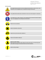
VAPOR PRESSURE
TESTER
MINIVAP VPXpert
OPERATION MANUAL
M-V1.11 SW-V1.10
Part 1 of 2
TABLE OF CONTENTS
PART 1 OF 2
GENERAL SAFETY SUMMERY ................................................................................................................. 5
Symbols .......................................................................................................................................... 6
1. GENERAL INFORMATION................................................................................................................. 8
1.1
Measuring standards ............................................................................................................... 9
1.1.1
Method DVPE according to ASTM D5191............................................................................. 9
1.1.2
Standard method VPx according to ASTM D6378 (SHT0769, JIS K2258-2) ........................ 9
1.1.3
Standard method ASVP according to IP394 and EN13016-1 .............................................. 9
1.1.4
Standard method VPCRx (crude oil) according to ASTM D6377 (IP 481, GOST 52340) .... 10
1.1.5
Absolute vapor pressure (EN 13016-2, IP 409) ................................................................. 10
1.1.6
Vapor-Liquid Ratio Temperature Determination of Fuels (ASTM D5188) ........................ 10
1.1.7
Standard Method LPG according to ASTM D6897 (up to 1000 kPa).................................. 11
1.1.8
Correlation Formulas for ASTM D5191, EPA, CARB......................................................... 11
1.1.9
Configurable methods ....................................................................................................... 12
1.1.10 Curve and multipoint measurements ............................................................................... 12
1.1.11 Accepted reference values ................................................................................................ 12
1.2
Measuring method ................................................................................................................. 13
1.2.1
Triple expansion method ................................................................................................... 14
1.2.2
Single expansion method .................................................................................................. 14
2. FEATURES...................................................................................................................................... 15
2.1
Technical data ........................................................................................................................ 16
3. UNPACKING................................................................................................................................... 17
4. INSTRUMENT SETUP..................................................................................................................... 20
4.1
Turning ON and OFF............................................................................................................... 20
4.2
External Keyboard.................................................................................................................. 20
4.3
Display .................................................................................................................................... 21
4.4
Internal Keyboards................................................................................................................. 22
4.5
User Management.................................................................................................................. 23
4.5.1
Install ADMINISTRATOR .................................................................................................... 23
4.5.2
User Levels ........................................................................................................................ 24
4.5.3
LOGIN / EDIT LOGIN .......................................................................................................... 25
4.6
SETUP..................................................................................................................................... 26
4.6.1
Change interface parameters and test USB ..................................................................... 27
4.6.2
Print out settings ............................................................................................................... 27
4.6.3
Maintenance....................................................................................................................... 27
4.6.4
Change Results Display..................................................................................................... 28
4.6.5
Change Date and Time....................................................................................................... 29
5. SELECT METHOD AND START MEASUREMENTS.......................................................................... 30
5.1
Select method ........................................................................................................................ 30
5.2
ONE BUTTON to start a measurement.................................................................................. 31
5.2.1
Start “LAST USED” Measurement..................................................................................... 31
5.3
Measurement according to preconfigured method .............................................................. 32
5.3.1
Start Measurements.......................................................................................................... 32
5.3.2
Rinsing cycles .................................................................................................................... 33
5.3.3
Filling temperature............................................................................................................ 34
5.3.4
Set Default Method ............................................................................................................ 34
5.4
Multipoint measurements...................................................................................................... 35
5.4.1
Configure Multipoint Measurements ................................................................................ 35
5.5
Curve measurements............................................................................................................. 36
5.5.1
Configure Curve Measurements ....................................................................................... 36
5.6
5.6.1
5.6.2
5.7
5.7.1
5.7.2
5.7.3
5.8
5.8.1
5.8.2
5.8.3
5.8.4
5.9
5.9.1
5.9.2
ASTM D5191/D6378 DVPE and D5188 Screening Method ..................................................... 37
Cooled and air saturated sample ..................................................................................... 37
D5191/D6378 and D5188 without sample preparation ..................................................... 37
User Defined Method ............................................................................................................. 38
User Defined Method ......................................................................................................... 38
Configure a User Defined Method ..................................................................................... 39
Start User Defined Method ................................................................................................ 40
Results.................................................................................................................................... 41
Single Result...................................................................................................................... 41
Check Formula .................................................................................................................. 42
Results List ........................................................................................................................ 43
Sort Results ....................................................................................................................... 44
SAVE results........................................................................................................................... 45
SAVE to USB....................................................................................................................... 45
Save all results to USB FLASH DEVICE............................................................................. 46
PART 2 OF 2
PRINTING ............................................................................................................................... 47
5.10
5.10.1 Print results list ................................................................................................................. 47
5.11
Delete results......................................................................................................................... 48
5.12
Export results to LIMS ........................................................................................................... 49
5.13
Crude Oil measurements....................................................................................................... 50
5.13.1 Vapor pressure of crude oil according to ASTM D6377 .................................................... 50
5.13.2 Recommended configuration for crude oil measurements ............................................. 50
5.13.3 Sample Preparation and Filling ........................................................................................ 50
5.13.4 Setup .................................................................................................................................. 51
5.13.5 Start the measurement ..................................................................................................... 52
5.13.6 Cleaning the measuring chamber..................................................................................... 52
5.14
LPG measurements ............................................................................................................... 53
5.14.1 Vapor pressure of LPG according to ASTM D6897............................................................ 53
5.14.2 Recommended configuration for LPG measurements ..................................................... 53
5.14.3 Outlet.................................................................................................................................. 53
5.14.4 Inlet .................................................................................................................................... 53
5.14.5 Start the measurement ..................................................................................................... 54
6. Mobile installation ......................................................................................................................... 55
6.1
DC/AC power converter PROwatt 300.................................................................................... 55
6.1.1
Installation ......................................................................................................................... 55
7. MAINTENANCE .............................................................................................................................. 56
7.1
Calibration .............................................................................................................................. 56
7.2
Refilling oil ............................................................................................................................. 56
7.3
Rinsing.................................................................................................................................... 56
7.3.1
Rinsing methods ................................................................................................................ 56
7.4
Error handling ........................................................................................................................ 58
CUSTOMER SUPPORT AND INFORMATION .......................................................................................... 59
MINIVAP VPXpert
OPERATION MANUAL
Part 1 of 2
GENERAL SAFETY SUMMERY
Review the following safety precautions to avoid injury and prevent damage to this product or any products
connected to it. To avoid potential hazards, use this product only as specified.
Only qualified, service-trained personnel who are aware of the hazards involved should remove the cover
from the instrument.
To avoid Fire or Personal Injury:
•
Use Proper Power Cord
Use only the power cord specified for this product and certified for the country of use. Avoid bending
or stretching the power cord.
•
Ground the Product
This product is grounded through the grounding conductor of the power cord. To avoid electric
shock, the grounding conductor must be connected to earth ground.
•
Do Not Operate Without Covers
Do not operate this product with covers or panels removed.
•
Use Proper Fuse
Use only the fuse type and rating specified for this product.
•
Do Not Operate With Suspected Failures
If you suspect there is damage to this product, have it inspected by qualified service personnel. Do
not ignore warnings on the display or warning signals. Please read the manual or call our
representative if you are not sure what to do.
•
Provide Proper Ventilation
Do not cover the ventilation slots. Place the instrument so that proper ventilation is guaranteed.
•
Place the instruments so that the main power switch is accessible every time
•
Do Not Operate in Wet/Damp Conditions
To avoid electric shock, do not operate this product in wet or damp conditions.
•
Do Not Operate in an Explosive Atmosphere
To avoid injury or fire hazard, do not operate this product in an explosive atmosphere.
•
Keep Product Surfaces Clean and Dry
•
Operate with proper protective Clothing (goggles, gloves, lab coat)
•
Be careful with flammable liquids
Flammable liquids should only be used by qualified employees. These substances should be used
with constant regard to the danger they pose to life and property. Under normal circumstances they
should always be used in a fume-hood away from possible sources of ignition. For further
information read the safety data sheet of the substance.
© AMETEK, Inc.
5
Symbols
Instrument
Attention – Dangerous high voltage
Protective Ground connection
Take care when touching – Hot surface
No mains connection. Instrument is turned off
Mains connected. Instrument is turned on
6
© AMETEK, Inc.
MINIVAP VPXpert
OPERATION MANUAL
Part 1 of 2
Manual symbols
This symbol indicates that the user has to follow the instructions or to be careful, as the
instrument can be damaged when not handled according to instructions.
This symbol indicates what must not be done in order not to harm people or instrument.
This symbol refers to other chapters in this manual that give detailed information about a
topic. It also highlights short and important information.
General symbols
Attention! Toxic substance!
Attention! Hazardous substance!
Attention! Corrosive and caustic substance!
Attention! Flammable substance!
<
Attention! Lethal voltage!
When opening the instrument and violation of safety rules, there is a risk of injury and
death. Before opening the instrument disconnect unit from mains!
Attention! High voltage!
© AMETEK, Inc.
7
1. GENERAL INFORMATION
The MINIVAP VPXpert is the most versatile instrument for the automatic determination of vapor pressures of
low-viscous liquids including hydrocarbons like gasoline and gasoline blends, crude oil, solvents and other
chemical compounds. The vapor pressure is determined with high precision in a pre-settable temperature
range of 0 to 120 °C (32 to 248 F). Pressures may be measured up to 1000 kPa (145 psi).
The instrument performs fully automatically with 10 mL of sample. The sample is drawn into a glass syringe
which is inserted into the Luer bore on the right hand side of the instrument. To avoid contamination with the
previous sample, 7.5 mL sample are used for rinsing the measuring cell.
The vapor pressure is determined with a sample volume of 1 mL.
An alternate sample introduction procedure is to install a small tube into the Luer bore so the sample is
drawn into the tester from a small container. Multiple measurements can be performed automatically from
the same sample.
MINIVAP VPXpert is a stand alone unit and does not require any accessories. The measured data is displayed
on an easy to read, robust and illuminated liquid crystal display. Using the MINIVAP VPXpert in the field, all
data is stored in the internal memory and transferred later.
According to the selected method the instrument will display the corresponding result in the main result
screen (e.g. DVPE, ASVP, Pabs (VP4) or RVPE). In a detailed result screen all correlated ASTM values are
shown together with Pabs, Pgas and Ptot.
Please note that for some selected methods you will have the choice of a correlated value, avoiding sample
preparation or the full compliance with the standard by performing air saturation and chilling (e.g. ASTM
D5191 or EN 13016-1). We highlight that the correlation will lead to better repeatability of the results and is
of course much faster. We recommend to select “no sample preparation”, if your companies SOPs allow.
For the determination of the absolute or true vapor pressure the dissolved air in the liquid is determined
with the measuring method developed by GRABNER INSTRUMENTS. The absolute vapor pressure of the
liquid (measurement against vacuum) is calculated from the total measured pressure minus the partial
pressure of the dissolved air.
For absolute vapor pressure determination no prior preparation of the sample is
necessary.
8
© AMETEK, Inc.
MINIVAP VPXpert
OPERATION MANUAL
Part 1 of 2
1.1
1.1.1
Measuring standards
Method DVPE according to ASTM D5191
Measurement of the total pressure of 1 mL of the air saturated sample at 37.8 °C (100 °F) exposed to a 5 mL
chamber and calculating the DVPE with the empirical formula
DVPE = 0.965 Ptot - 3.78 [kPa]
DVPE = 0.965 Ptot - 0.548 [psi]
1.1.2
Standard method VPx according to ASTM D6378 (SHT0769, JIS K2258-2)
No Chilling and air saturation necessary.
The fastest and safest way of determining a vapor pressure of gasoline was developed by GRABNER
INSTRUMENTS. This method uses the value for the total measured pressure and the partial pressure of the
dissolved air to calculate the absolute vapor pressure of the sample. The designation „absolute“ was rejected
by some members of the study group and the new name is VPx, were the x stands for the vapor-liquid ratio.
A large interlaboratory study on more than 2500 samples showed an excellent agreement of this absolute
vapor pressure and the DVPE according to ASTM D5191.
For this procedure the first and second number is set to 1,000 and the third number is set to the respective
bias according to ASTM, EPA or CARB.
DVPE = 1.000xPtot - 1.000xPgas - bias psi
The advantages of this method are twofold:
The measured values are valid also for other temperatures then 37,8°C (100 F).
Sample preparation according to REID is not necessary.
1.1.3
Standard method ASVP according to IP394 and EN13016-1
This measuring method is the new standard in Europe for gasoline vapor pressure measurement.
The measuring procedure is equivalent to the ASTM D5191.
It is most unfortunate that Europe did not adopt the new method of ASTM namely ASTM D6378. The
corrected ASVP is identical with D5191 and the AVP is identical with VPx of D6378. Beside the confusion, the
user still has to accept the cumbersome and time consuming procedure of chilling and air saturation, which
is still the main source of reduced reproducibility. In ASTM D6378 a bias statement to ASTM D5191 is
included that allows the use of D6378 instead of EN13016.
© AMETEK, Inc.
9
1.1.4
Standard method VPCRx (crude oil) according to ASTM D6377 (IP 481, GOST 52340)
It should be stressed that the round robin for ASTM D5191 did NOT include crude oil samples and the
correlation formula should not be applied. Crude oil must be handled with greatest care in order not to loose
high volatiles. ASTM D5191 sample handling procedures for air saturation will have a significant influence on
the vapor pressure. Since crude oil should hardly contain any dissolved air, it is better to measure the total
pressure and report this pressure as the vapor pressure. A new mini method for crude oil ASTM D6377
(GOST 52340) is based on a single expansion with the sample introduced under pressure from a floating
piston cylinder. For the correlation to ASTM D323 the following formula was developed according to the last
draft of the Standard Test Method for Vapor Pressure of Crude Oil: VPCR4 (V/L=4)
RVPE (D 323) = 0.752*Ptot + 6.07kPa (0.880psi)
Stirring of the sample during the measurement is mandatory, by use of the integrated shaker.
MINIVAP VPXpert also covers the whole standard including vapor pressure at elevated temperatures.
1.1.5
Absolute vapor pressure (EN 13016-2, IP 409)
The absolute vapor pressure of a liquid is defined as the pressure built-up from the liquid against vacuum at
a given temperature. The problems faced in measuring the vapor pressure of liquids are caused by the fact
that all liquids contain varying quantities of dissolved gases (primarily air). Except for water and a few other
substances, the gas content in a liquid is not known.
When a liquid is introduced into an evacuated cell, the dissolved gas escapes and builds up a partial
pressure in addition to the vapor pressure of the liquid. As the two pressures add up, it is impossible to
determine the true vapor pressure of the liquid.
With MINIVAP VPXpert a measuring technique is used, which determines exactly the partial pressure of the
dissolved air. This partial air pressure is used for the exact determination of the absolute vapor pressure.
It should be emphasized that this correction is not determined empirically but by exact measurement.
Fully automatic measurements of the absolute vapor pressure can be performed for preselected
temperature steps or continuously over the whole temperature range from 0 to 120 °C (32 to 248 °F)
including a plot of the vapor pressure versus the temperature.
1.1.6
Vapor-Liquid Ratio Temperature Determination of Fuels (ASTM D5188)
ASTM D5188 covers the determination of the temperature at which vapor produces pressure of 101.3 kPa (1
atmosphere) in a fixed chamber. This method requires cooled (0 to 1°C, 32 to 34°F) and air saturated
samples. The MINIVAP VPXpert result is equivalent to the results determined by the ASTM D 5188 method.
For automotive fuel specifications the T(V/L = 20) is determined. For advanced volatility studies the MINIVAP
VPXpert incorporates multipoint measurements to assess temperature tendency
for V/L ratios from 0.1:1 to 100:1.
The VPXpert allows fast automatic screening per ASTM D5191 and D5188
in a single run.
10
© AMETEK, Inc.
MINIVAP VPXpert
OPERATION MANUAL
Part 1 of 2
1.1.7
Standard Method LPG according to ASTM D6897 (up to 1000 kPa)
This method is designed for the automatic determination of vapor pressure of liquefied petroleum products,
measured against vacuum, relative to atmospheric pressure, at a V/L ratio of 0.1:1 to 4:1. Typically the vapor
pressure of LPG is measured at 37.8°C and a V/L ratio of 0.5:1. The results of D6897 are equivalent to the old
traditional standard ASTM D1267.
The MINIVAP VPXpert covers a presetable temperature range of 0 to 120°C (32 to 248°F). In the standard
MINIVAP VPXpert, pressures may be measured up to 1000 kPa (145 psi).
1.1.8
Correlation Formulas for ASTM D5191, EPA, CARB
All correlation formulas for the different methods can be viewed prior to measurement and are shown on the
results printout after measurements. The most important correlation formulas are:
Correlation Formulas based on ASTM D5191 / EN 13016-1 = SAMPLE PREPARATION (Cooling & Air Saturation)
ASVP = Ptot if sample prep has been performed
EN 13016-1
ASTM
DVPE = 0.965*ASVP - 3.78 kPa (0.548 psi)
corr.: D5191
EPA
DVPE = 0.956*ASVP - 2.39 kPa (0.347 psi)
corr.: D4953
CARB
RVPE = 0.972*ASVP - 4.93 kPa (0.715 psi)
corr.: D323
Correlation Formulas based on ASTM D 6378 (Triple Expansion) = NO SAMPLE PREPARATION
AVP = VP4 = Pabs = Ptot - Pgas
D6378
ASVP = 1.036*Ptot - 1.036*Pgas + 2.876 kPa (0.412 psi)
corr.: EN 13016-1
ASTM
DVPE = 1.000*Ptot - 1.000*Pgas - 1.005 kPa (0.15 psi)
corr.: D5191
EPA
DVPE = 1.000*Ptot - 1.000*Pgas - 0.137 kPa (0.02 psi)
corr.: D4953
CARB
RVPE = 1.000*Ptot - 1.000*Pgas - 1.575 kPa (0.23 psi)
corr.: D323
Correlation Formula for VPCR4: ASTM D 6377 (notice sample handling recommendations)
VPCR4 = Ptot (single expansion)
RVPE = 0.752*Ptot - 0.000*Pgas + 6.070 kPa (0.880 psi)
Glossar:
D6377
corr.: D323
DVPE
“Dry” REID-equivalent vapor pressure, calculated with the selected correlation
formula 1 (ASTM D5191) or 2 (ASTM D4953)
RVPE
“Wet” REID-equivalent vapor pressure, calculated with the selected correlation
formula 3 (ASTM D323)
AVP
Absolute Vapor Pressure of the liquid: Pabs = Ptot - Pgas
ASVP
Air Saturated Vapor Pressure
Sample Preparation
Cooling & air saturation of the sample prior to the measurement
Please note that the Grabner Instruments EPA and CARB methods (ASTM Formula, EPA
Formula and CARB Formula) are preconfigured in the analyzer.
© AMETEK, Inc.
11
1.1.9
Configurable methods
User methods can be configured easily with the MINIVAP VPXpert via various user methods.
1.1.10 Curve and multipoint measurements
In addition to single point measurements the MINIVAP VPXpert includes configurable Multi-Point and Curve
measurements for ASTM, EN, IP, GOST, JIS and SHT standards.
1.1.11 Accepted reference values
ASTM D6378 (2009)
Possible reference fluids, corresponding to the absolute vapor pressure Pabs at 37.8°C and a V/L of 4:1:
Reference Fluid
Pentane
2,2 Dimethylbutane
2,3 Dimethylbutane
Measured Parameter
ARV VP4(37.8°C)
ARV VP4(37.8°C)
ARV VP4(37.8°C)
Accepted Testing Range for Reference Fluid
107.9 ± 1.2 kPa (15.65 ± 0.17 psi)
68.8 ± 1.2 kPa (9.98 ± 0.17 psi)
51.7 ± 1.2 kPa (7.50 ± 0.17 psi)
ASTM D5191 (2010) + EN 13016-1 (2007)
Possible reference fluids, corresponding air saturated vapor pressure Ptot at 37.8°C and a V/L of 4:1:
Pentane
2,2 Dimethylbutane
2,3 Dimethylbutane
Ptot (37.8°C)
Ptot (37.8°C)
Ptot (37.8°C)
112.8 ± 1.2 kPa (16.36 ± 0.17 psi)
74.1 ± 1.2 kPa (10.75 ± 0.17 psi)
57.1 ± 1.2 kPa (8.28 ± 0.17 psi)
ASTM 5188 (2010)
Possible reference fluid, air saturated, Temperature at T (V/L = 20):
Pentane
T (V/L = 20)
36,1°C (96,9°F)
ASTM 6377 (2008)
Possible reference fluids, corresponding air saturated vapor pressure ASVP, 37.8°C, V/L of 4:1 (VPCR4):
Pentane
2,2 Dimethylbutane
2,3 Dimethylbutane
VPCR4 (37.8°C)
VPCR4 (37.8°C)
VPCR4 (37.8°C)
112.8 ± 1.2 kPa (16.36 ± 0.17 psi)
74.1 ± 1.2 kPa (10.75 ± 0.17 psi)
57.1 ± 1.2 kPa (8.28 ± 0.17 psi)
ASTM 6897 (2009)
Possible reference fluids, the LPG vapor pressure VPLPG at a V/L of 0.5:1:
Butane
Pentane (air saturated)
VPLPG (37.8°C)
VPLPG (70.0°C)
356.5 ± 6 kPa (51.7 ± 0.9 psi)
310.0 ± 6 kPa (44.96 ± 0.9 psi)
Please note that in ASTM D5188 no “Acceptable Testing Range for Reference Fluids” is
listed.
12
© AMETEK, Inc.
MINIVAP VPXpert
OPERATION MANUAL
Part 1 of 2
1.2
Measuring method
The measuring principle is a measurement of the vapor pressure of the sample against vacuum.
Vacuum is produced with a piston by an expansion after drawing in the sample and closing the inlet valve,
producing the same effect as injecting the sample into an evacuated cell.
The sample is introduced through the Luer sample inlet (3) and the sample inlet valve (4) into the measuring
chamber. The automatic sample introduction and the volume adjustment is accomplished by
a piston with an integrated pressure transducer (1). The measuring chamber (2), with a total volume of 5 mL,
is rinsed with 3 x 2.5 mL and filled with the appropriate amount of sample. After closing the valve (4), single
or triple expansion to 5 mL (with vacuum created by piston withdrawal) is obtained by additional piston
strokes. The temperature of the measuring cell is controlled by a high-power thermoelectric module (5) and
measured with a precision Pt100 RTD sensor (6).
© AMETEK, Inc.
13
1.2.1
Triple expansion method
Rinsing n times. (no. of rinsing cycles)
1.
Valve stem (4) position inlet open; outlet is closed
2.
Piston (1) expands (2.5 mL). Sample for rinsing is introduced
3.
Valve stem inlet side closed; Valve stem position outlet open
4.
Piston (1) moves to lowest position directly above the valve; sample is being
discharged.
5.
Valve stem to position inlet open; outlet side closed
Filling
6.
Piston (1) expands to fill sample (1 ml )
7.
Valve stems (4) are closed
Measuring
8.
Piston (1) performs first expansion (1.7 mL)
9.
Temperature increase to set measuring temperature
10.
First equilibrium time (3 min) and first pressure measurement (partial pressure 1)
11.
Piston performs second expansion (2.5 mL)
12.
Second equilibrium time (1 min) and second pressure measurement
(partial pressure 2)
13.
Piston performs third expansion (5 mL)
14.
Third equilibrium time (1 min) and third pressure measurement (partial pressure 3)
15.
Calculation of total vapor pressure (Ptot), dissolves air (Pgas) and absolute vapor
pressure. Display of results.
16.
Valve stem to position outlet open; inlet side closed
17.
Piston (1) moves to lowest position directly above the valve; sample is being
discharged.
The gas correction is determined of the 3 pressure measurements (3 partial pressures). Due to this
determination the total vapor pressure, the absolute vapor pressure and the dissolved air can be measured.
1.2.2
Single expansion method
Rinsing n times. (no. of rinsing cycles)
1.
Valve stem (4) position inlet open; outlet is closed
2.
Piston (1) expands (2.5 mL). Sample for rinsing is introduced
3.
Valve stem inlet side closed; Valve stem position outlet open
4.
Piston (1) moves to lowest position directly above the valve; sample is being
discharged.
5.
Valve stem to position inlet open; outlet side closed
Filling
6.
Piston (1) expands to fill sample (1 ml )
7.
Valve stems (4) are closed
Measuring
8.
Piston (1) performs a single expansion (5 mL)
9.
Temperature increase to the adjusted measuring temperature.
10.
Equilibrium time (depending on crude oil) and pressure measurement
11.
Calculation and display of the vapor pressure.
12.
Valve stem to position outlet open; inlet side closed
13.
Piston (1) moves to lowest position directly above the valve; sample is being
discharged.
The vapor pressure is determined from the pressure measurement at 5 mL.
14
© AMETEK, Inc.
MINIVAP VPXpert
OPERATION MANUAL
Part 1 of 2
2. FEATURES
•
•
•
•
•
•
•
•
•
•
•
•
•
•
•
•
•
•
•
•
•
•
•
Only 10 mL of sample for complete measurement, 1 mL w/o rinsing
No sample preparation for absolute values
No vacuum pump necessary
Accurate determination of absolute vapor pressure
Measurement is fully automatic
No accessories required
Widest temperature range of 0 to 120 °C (32 to 248 °F)
Built-in diagnostic and safety features
Typical measurement time for single point of only 5 minutes
Built-in USB and RS 232 Interfaces
Integrated shaker for crude oil samples
Sampling Pro™ Valve Design
Maintenance free, heavy duty measuring cell
Automatic Piston Lubrication
One Button – One Touch Usability
Large, durable display – Fit for field use
Automatic multiple measurement
Lightweight and compact, portable tester
Optional 12 V DC battery operation for field use
Determination of the V/L ratio temperature
Ramp/Curve measurements
Support of ANY PCL-compatible USB printer; serial and compact printer support
User access control
MEASUREMENTS:
• DRY REID VAPOR PRESSURE – ASTM D5191, D4953/EPA, D5482, D5190
• ABSOLUTE VAPOR PRESSURE – ASTM D6378
• VAPOR PRESSURE OF CRUDE OIL – ASTM D6377, ASTM D323, GOST 52340, IP 481
• ASVP ACCORDING TO EN 13016, IP 394, IP 409– Air saturated vapour pressure
• RVPE FOR GASOLINE AND CRUDE OIL - CARB
• VAPOR/LIQUID RATIO TEMPERATURE – according to ASTM D5188 but without air saturation
© AMETEK, Inc.
15
2.1
16
Technical data
Temperature range
0 to 120 °C (32 to 248 °F)
Accuracy of temperature reading
Better than +/- 0.1 °C (+/- 0.2 °F)
Environmental Specifications
Operating Temperature: 0°C to 50°C (32°F to 122°F)
Operational humidity up to 80% RH
non condensing
Pressure range
0 to 10 000 hPa
0 to 1000.0 kPa
0 to 10.000 at
0 to 145.00 psi
Linearity
0.1 % FSC
Zero drift
max 0.3 kPa
Repeatability
r ≤ 0.3 kPa (@ 37.8°C, 70 kPa)
Reproducibility
R ≤ 0.7 kPa (@ 37.8°C, 70 kPa)
Adjustable vapor to liquid ratio in the
menus:
Standard V/L=4.0
Absolute V/L = 0.02 to 4.0
V/L V/L = 0.1 to 100.0
Crude Oil 1 to 3 V/L = 0.02 to 4.0
LPG V/L = 0.02 to 4.0
Communication languages
English, German, French, Spanish, Portuguese
Units of temperature
Celsius or Fahrenheit
Units of pressure
hPa, kPa, psi, at, mmHg
Power requirements
90-264 V AC, 45-63 Hz, 200 W (Switching Power Supply)
Optional
DC/AC Power converter for operation with car battery
Fuse
Type FST 5x20mm time lag T1.25A/250V
IR35A/250V
AC IEC 60127-2/3
Physical dimensions
W x H x D = 153 x 368 x 277 mm
W x H x D = 10 x 14.5 x 10.9 inches
Weight
appr. 9 kg (20 pounds)
© AMETEK, Inc.
MINIVAP VPXpert
OPERATION MANUAL
Part 1 of 2
3. UNPACKING
The instrument is originally shipped with a specially designed shock proof box. Please keep this box. You
might need it to ship the instrument in for calibration.
© AMETEK, Inc.
1 Vapor pressure tester
MINIVAP VPXpert
VPXPERT
1 syringe 10 ml
CCA210-206-00
1 Luer connection for direct sample
input
CCA100-230-00
1 Vacuum hose 6/4 with standard
connector
CCA100-411-00
1 Disposal container with lid
CCA210-300-00
1 Outlet tube
CCA210-400-00
1 Piston oil 100ml
CCA210-207-00
17
1 low cost syringe 2ml
CCA100-420-00
1 Power supply cable
(EU left ; US right)
A1000-998-00 (115V)
A1000-999-00 (230V)
1 RS 232 Printer cable with adapter
A1000-110-00
1 pc. USB device
1 Operation Manual
1 Test certificate
1 CD – MINIWIN
Options:
PROwatt 300 power converter
12V vehicle battery operation
CCA100-090-00
Mini - keyboard
A1000-600-00/GER
A1000-600-00/US
Keyboard - cover
A1000-601-00/GER
A1000-601-00/US
18
© AMETEK, Inc.
MINIVAP VPXpert
OPERATION MANUAL
Part 1 of 2
Crude Oil Options:
© AMETEK, Inc.
Floating piston cylinder (FPC 250)
CCA215-500-00
Special instrument sample inlet for
crude oil (if existing instrument only
has luer inlet)
VPX-COUPLING
Pressure regulator for FPC 250
VPX-PRESSURE-REG
Filling tube for FPC 250
CCA215-502-00
Filling tube (PTFE) with 2 quick
connectors and integrated metal filter
for pressurized samples connecting
instruments with mounted crude oil
inlet and FPC 250 (CCA215-500-00)
CCA210-210-00
Filling tube (PTFE) with 1 quick
connector for non-pressurized
samples, like gasoline for instruments
with mounted crude oil inlet
CCA210-211-00
Additional manometer for back
pressure measurement
CCA215-503-00
19
4. INSTRUMENT SETUP
1
3
2
4.1
Turning ON and OFF
4
5
Please wait at least 7 seconds after switch off, before you switch the instrument on again!
4.2
External Keyboard
On the rear panel of the instrument you find a connector for a PC-keyboard (Please use an IBM PC-AT or
compatible keyboard). A keyboard with protection cover can be ordered from GRABNER INSTRUMENTS
directly. Connect the keyboard.
20
© AMETEK, Inc.
MINIVAP VPXpert
OPERATION MANUAL
Part 1 of 2
4.3
Display
The keys on the front panel have the following functions:
Stop measurement at any time / Escape a menu
Start measurement
Confirm selected operation / Summon virtual keyboard to insert characters
Modify characters
Change the cursor position
Execute special functions
Press
© AMETEK, Inc.
to return to the previous menu any time.
21
4.4
Internal Keyboards
There are two ways to insert characters, e.g. when entering names, sample IDs or location, without
attaching an external keyboard.
:
1. Press “ENTER” on the character field to summon a virtual keyboard
ENTER
Shift + ENTER
Shift + RUN
<-- / --> + ENTER
bck
SPC
Program Favorite Strings
Select Favorite String
2.
22
Inserat a capital letter
Insert a small letter
Insert a special character
Move cursor left and right within the string
Back: Delete one character in the string
Space: Generate a space between characters
Two places for favorite strings are available. If you want to use
your current string as favorite, move the cursor to one of the
fields (“n-Pentane” or “neo-Hexane” in the example above) and
press Shift + ENTER. Your new favorite string is stored.
Move the cursor to your favorite string and press ENTER.
If you do not want to use the virtual keyboard, use the + / - button to scroll through the characters,
use SHIFT and +/- for fast scrolling through the characters. Press SHIFT and simultaneously to
delete characters.
© AMETEK, Inc.
MINIVAP VPXpert
OPERATION MANUAL
Part 1 of 2
4.5
User Management
Once the first user is installed, all operators will have to log in to operate the MINIVAP
VPXpert. If you do not want to have to log in, do not configure the user management or
delete all users.
The first user will always have ADMINISTRATOR level to prevent locking out oneself from
the instrument.
4.5.1
9
9
9
9
9
Install ADMINISTRATOR
On the Main Screen place the cursor on “USER” and press “ENTER”.
Insert Username and Password by using the toggle buttons
Select User Level with different rights:ADMINISTRATOR, ADVANCED or STANDARD USER
Place the cursor on “SAVE” and press “ENTER”
The new user will show as “LOGGED IN” on the Main Screen
© AMETEK, Inc.
23
4.5.2
User Levels
Three user levels are available in the MINIVAP VPXpert:
STANDARD USER:
The Standard User has full control to do measurements:
9 Select method
9 Select sample ID
9 Start measurement
9 Read, print and delete results
9 Start a rinsing cycle
The standard user cannot access other menus.
ADVANCED USER:
The Advanced User can access all measurement and setting related menus, but he´s not allow to access
the menus TEST and CALIBRATION.
ADMIN:
The Administrator has full control over the instrument, he´s able to access and work in the menus TEST and
CALIBRATION.
Only users with equal or lower than your current user level can be created. To add a new user
9 Move the cursor on “USER” and press “ENTER”
9 Move the cursor on “USER” and press “NEW”
9 Continue analogue to instructions “Install ADMINISTRATOR”
Press “SHIFT” and “+/-“ for fast scrolling through the characters, e.g. when inserting the
Location. Press “SHIFT” and SIMULTANEOUSLY to delete characters.
24
© AMETEK, Inc.
MINIVAP VPXpert
OPERATION MANUAL
Part 1 of 2
4.5.3
LOGIN / EDIT LOGIN
9
9
9
9
On the Main Screen place the cursor on “USER” and press “ENTER”.
Use the toggle buttons to select the User
Place the cursor on “LOGIN” and press “ENTER”.
Choose either to LOGIN or to EDIT and press “ENTER”
Parameters LOGIN Menu
Del
New
SortUser
SortRght
Logout
Login
End
© AMETEK, Inc.
Delete User (only as Administrator)
Create New User
Sort by User Name
Sort by User Rights
Log Out Current user
Log In as new user
Return to the previous menu
25
4.6
SETUP
On the Main Screen move cursor on “SETUP” and press “ENTER”.
Move the cursor around and use the +/- keys to change parameters.
Configurable Parameters:
Location
USB Format
autom.ResOut
unit Temp
unit Press
Language
Enter name
Data format for saving results, select either .csv or .txt
Automatic Results Output after measurement, options:
• Off
• Prn: Result automatically printed
• Prn Det: Results Details automatically printed
• USB: Result automatically saved to USB
• USB Det: Results Details automatically saved to USB
Choose the temperature units shown on the VPXpert:
°C or °F
Choose the temperature units shown on the VPXpert:
kPa, psi, hPa, mbar, at, mmHg
Choose your language
Press “SHIFT” and “+/-“ for fast scrolling through the characters, e.g. when inserting
the Location. Press “SHIFT” and SIMULTANEOUSLY to delete characters.
26
© AMETEK, Inc.
MINIVAP VPXpert
OPERATION MANUAL
Part 1 of 2
4.6.1
Change interface parameters and test USB
Move the cursor to the characters and use the +/- keys to change settings for serial interface and USB.
4.6.2
Print out settings
Move the cursor on “PRINT” and press “ENTER” to print the settings of the analyzer.
4.6.3
Maintenance
Please refer to the service manual for detailed instructions on the maintenance menu.
© AMETEK, Inc.
27
4.6.4
9
9
9
28
Change Results Display
In the SETUP Menu move the cursor on “MAINT.” and press “ENTER”
Use the +/- keys to change the screen to “ResultMenu”
Use the cursor to move to the settings and select your preferred setting with the +/- keys:
o Simple Default: The result screen shows the result according to the selected standard (e.g.
for ASTM D6378 the result shows the Pabs, for D5191 the results shows the DVPE).
Details are available if you click on “DETAILS”.
o Detail Default: Per Default, all results are shown in the detailed mode.
Results listed are DVPE, RVP, Ptot, Pgas and Pabs, etc.
© AMETEK, Inc.
MINIVAP VPXpert
OPERATION MANUAL
Part 1 of 2
4.6.5
Change Date and Time
To change DATE and TIME, move the cursor to the characters and use the +/- keys to change. For saving
the new values, move the cursor on “SET” and press “ENTER”.
To change the DATE and TIME FORMAT, move the cursor to “FORM DATE” or “FORM TIME” and use
the +/- keys to change DATE and TIME FORMAT.
© AMETEK, Inc.
29
5. SELECT METHOD AND START MEASUREMENTS
5.1
Select method
To decide for a method simply follow this procedure (example for method selection according to ASTM):
ptot-pgas
Pabs(VP4)
D6378
0.965*ptot – 0*pgas – 3.78kPa
D5191 ASTM
Sample
Preparation?
ASTM
DVPE
(sample prep)
YES
DVPE
(corr)
NO
Selection of
the method for
the RESULT
1*ptot – 1*pgas – 1.005kPa
0.956*ptot – 0*pgas – 2.39kPa
D4953 EPA
Sample
Preparation?
YES
DVPE
(corr)
NO
Selection of
regional
STANDARD
DVPE
(sample prep)
1*ptot – 1*pgas – 0.137kPa
GAS
D323 CARB
EN
Gasoline
Gasoline +
Sample Prep
Crude Oil
GAS+
PREP
1*ptot – 1*pgas – 1.575kPa
0.972*ptot – 0*pgas – 4.93kPa kPa
RVPE
(gasoline)
RVPE
(gasoline)
(sample prep)
IP
RVPE
(VPCR4)
GOST
CRUDE
0.752*ptot – 0*pgas + 6.070kPa
JIS
User Methods
ptot
Ptot (VPCR4)
D6377
EPA and CARB methods:
• ASTM = D5191 with Sample Preparation
• EPA
= D4953 with Sample Preparation
• CARB = D323 (Gasoline) with Sample Preparation
30
© AMETEK, Inc.
MINIVAP VPXpert
OPERATION MANUAL
Part 1 of 2
5.2
ONE BUTTON to start a measurement
Press “RUN” on the Start Screen to start the listed DEFAULT METHOD measurement.
On the following screen either insert “SAMPLE ID“ or press “RUN” to use a default name.
/
To select a different method, see the following section.
5.2.1
Start “LAST USED” Measurement
Move the cursor to “MEASURE” and press “ENTER”. Press “RUN” on the Method Screen to immediately
start LAST USED METHOD measurement (here shown ASTM D6378 as last used).
© AMETEK, Inc.
31
5.3
Measurement according to preconfigured method
9
9
9
9
5.3.1
Place the cursor on “MEASURE” and press “ENTER”
Toggle up and down to select ASTM, EN, IP, GOST or JIS standard
Toggle right to select your method (e.g. ASTM D6377, D6378, D5191)
Press “ENTER” to continue
Start Measurements
Sample ID
Measurement Cycles (up to 9 unattended successive
measurements with the same settings possible)
Rinsing Cycles
Filling (TFill) and Measuring Temperature (Tmeas)
Sample Preparation / No sample Preparation
32
© AMETEK, Inc.
MINIVAP VPXpert
OPERATION MANUAL
Part 1 of 2
Press “SHIFT” and “+/-“ for fast scrolling through the characters, e.g. when inserting the
Location. Press “SHIFT” and SIMULTANEOUSLY to delete characters.
Press RUN to start the measurement
5.3.2
Rinsing cycles
Determines the number of rinsing cycles and the necessary amount of liquid for one measurement. For each
rinsing cycle approximately 2.5 mL are required. The supplied 10 mL syringe is large enough for 3-4 rinsing
cycles.
3 rinsing cycles are standard settings and must not be decreased in order to avoid
contamination of previous tested samples. To further minimize cross contamination a
higher number of rinsing cycles may be chosen (see Chapter 7 – Rinsing).
© AMETEK, Inc.
33
5.3.3
Filling temperature
The temperature of the measuring chamber at which the sample is filled, can be programmed in this menu.
The default value is 20 °C (68 °F). For samples like crude oil with a pour point above 15 °C (60 °F) it will be
necessary to increase this temperature for proper filling.
Program the desired temperature of the measuring chamber, at which the sample is filled.
The nominal value is 20°C which is good for all measurements.
Don’t set filling temperature too high. Samples with high vapor pressure at lower
temperatures would be pushed out of the inlet. The instrument has no possibility to rinse
the cell appropriately or to introduce 1ml sample accurately. This would cause wrong
results.
5.3.4
Set Default Method
In the Measuring Menu move the cursor to “SET DEF.” to lock current method as default method.
Press “ENTER” to lock the default method.
34
© AMETEK, Inc.
MINIVAP VPXpert
OPERATION MANUAL
Part 1 of 2
5.4
5.4.1
Multipoint measurements
Configure Multipoint Measurements
Usually Single Point measurements are performed with the MINIVAP VPXpert.
In addition measurements of the sample at various temperatures are possible.
To start a multipoint measurement
9 Move the cursor to “MultiP” and press “ENTER”
9 Choose up to 10 different temperature values by using the +/- icons
9 Set the V/L ratio
9 Start the measurement by pressing “RUN”
Results according to the selected method are listed.
In the above example, a multipoint measurement according to ASTM D6378 has been
performed. The results shown as p(kPa) and pgas(kPa) refer to absolute vapour pressure
(Pabs) and the partial gas pressure (Pgas) as per method ASTM D6378.
© AMETEK, Inc.
35
5.5
5.5.1
Curve measurements
Configure Curve Measurements
To start a curve measurement
9 Move the cursor to “Curve” and press “ENTER”
9 Set the Start Temperature T_start and the Final Temperature T_Final
9 Set StepWidth for curve measurement (Default: 1°C steps are measured between T_start and
T_Final)
9 Set Heat Rate (Default: 1°C/min.)
9 Set the V/L ratio
9 Start the measurement by pressing “RUN”
Results according to the selected method are listed.
36
© AMETEK, Inc.
MINIVAP VPXpert
OPERATION MANUAL
Part 1 of 2
5.6
ASTM D5191/D6378 DVPE and D5188 Screening Method
To accelerate measuring, a combined ASTM D5191/D6378 and D5188 measurement at V/L = 20 is available.
To start a measurement select “ASTM D5191 & D5188” and press “ENTER”.
5.6.1
Cooled and air saturated sample
Select “sample prep”, if you want to measure a cooled and air saturated sample.
ASTM D5191 DVPE and D5188 (V/L = 20) are measured consecutively. For each measurement a new sample
is used. Do not remove the sample container during the test. Make sure that the sample is kept at 0°C in a
cooling bath or a similar device during the test to prevent sample outgassing. While typical gasoline samples
have a VP < 1 bar at 0°C, samples containing high amounts of gases (e.g. propane) will start outgassing
during the test, even if the sample temperature is kept at 0°C.
5.6.2
D5191/D6378 and D5188 without sample preparation
Select “no sample prep”, to measure without sample preparation. The DVPE according to ASTM D5191 and
D6378, as well as the ASTM D5188 (V/L = 20) is measured. Because D5188 still requires sample preparation,
the D5188 measurements w/o sample preparation will generate a small sample specific bias for gasolines.
Please do not use a cooled and air saturated sample, if you have selected ”no sample prep”, because this
will in turn lead to a wrong DVPE result.
© AMETEK, Inc.
37
5.7
User Defined Method
5.7.1
User Defined Method
Measurements according to standards are done with predefined equilibrium times.
For User Defined Measurements equilibrium times and various other parameters are freely programmable.
Equilibrium times are used for the determination of the partial gas pressure.
Configurable Parameters are:
Method name
Testing method
Equilibrium times
t(Equ1) =
t(Equ2,3) =
t(step) =
Shaker
Measurement Cycles
Rinsing Cycles
Tmeas
Tfill
MultiP
Formula
Curve
Set Def.
38
Single or triple expansion
Equilibrium time after the first expansion
Equilibrium time after the second and third expansion
Is used for further measuring points after the gas correction.
Equilibrium time for next measuring temperature.
On or Off
Number of measurements with the same sample
Number of Rinsing cycles done prior to every measurement
Measuring temperature
Filling temperature
Select Points for Multipoint Measurement
Adjust the correlation formula
Select Temperature Range, Step Width and Heat rate for
Multipoint measurements
Set the current configuration as your default measurement
© AMETEK, Inc.
MINIVAP VPXpert
OPERATION MANUAL
Part 1 of 2
5.7.2
Configure a User Defined Method
If you want to configure the analyzer e.g. to measure according to ASTM D5482, set the following
parameters:
Method name
Testing method
Equilibrium times
t(Equ1) =
t(step) =
Shaker
Measurement Cycles
Rinsing Cycles
Tmeas
Tfill
DVPE Formula
ASTM D5482
Single expansion
300 seconds
60 seconds
off
1
3
37.8°C
Set the filling temperature between 0 and +4,5°C
Adjust the formula to
DVPE = 0.965*ptot + 0.000*pgas + 0.540 kPa.
Press “Save” afterwards.
Press “SAVE” to store the formula.
Press “RUN” to start the measurement immediately with the above listed settings.
ASTM D5482 requires cooling and air saturation of the sample prior to measurement.
© AMETEK, Inc.
39
5.7.3
9
9
9
40
Start User Defined Method
Place the cursor on a free User Method and press “ENTER”
Toggle up and down and use the +/- keys to change the settings
Press “RUN” to start the measurement
© AMETEK, Inc.
MINIVAP VPXpert
OPERATION MANUAL
Part 1 of 2
5.8
Results
5.8.1
Single Result
Results are shown directly after measurement.
Highlighted is the result according to the previously selected standard.
For additional values (Pabs, Ptot, Pgas) and Standards (DVPE according to D5191, D4953 or RVPE
according to D323) move the cursor over “DETAIL” on the Result Screen and press “ENTER”.
Detailed results are available only for single point measurements. Detailed results can be
shown per DEFAULT, for instructions please refer to section SETUP - “4.5.3 Maintenance”.
© AMETEK, Inc.
41
5.8.2
Check Formula
To check the formula used for the current measurement, move the cursor to “FORMULA” on the Result
Screen and press “ENTER”.
To leave the Formula Screen press “ENTER” again.
Formulas used are saved automatically with the result and will be transferred once
results are downloaded.
Press
42
to return to the previous menu any time
© AMETEK, Inc.
MINIVAP VPXpert
OPERATION MANUAL
Part 1 of 2
5.8.3
Results List
Two results lists can be accessed and downloaded separately
1. Single and Multipoint Results (POINT | RES)
2. Curve measurement results (RES | CURVE)
Access to results lists
9 Place the cursor on “POINT | RES”or “RES | CURVE” on the Start Screen and press “ENTER”
9 Toggle up and down to select a result
9 Place the cursor on “SHOW” and press “ENTER”
Single and Multipoint Results
Curve Measurement Results
1
© AMETEK, Inc.
43
5.8.4
Sort Results
To sort the results list for Name, Time or Method place the cursor on “Sort” and press “ENTER”.
Available options
SortTime
SortName
SortMeth.
SortRes.
44
Sort per Time
Sort per Name
Sort per Method
Sort per Result
© AMETEK, Inc.
MINIVAP VPXpert
OPERATION MANUAL
Part 1 of 2
5.9
SAVE results
5.9.1
SAVE to USB
9
9
9
9
Insert USB stick as shown below
Connection is indicated by audible “BEEP” and the red light showing on the flash device.
Move the cursor over “to USB” and press “ENTER” to download the result onto the USB
DO NOT REMOVE the USB until the “USB” sign is no longer highlighted
1
2
3
2
4
5
6
© AMETEK, Inc.
45
5.9.2
9
9
Save all results to USB FLASH DEVICE
View the results list, insert USB stick, move the cursor “to USB” and press “SHIFT” and “ENTER”
DO NOT REMOVE the USB until the “USB” sign is no longer highlighted
+
1
2
3
4
Please note that only the results list you are currently working in is saved to USB:
9
9
46
Measurement Results Overview (Single & Multipoint Measurements)
Curve Result Overview (Curve Measurements)
© AMETEK, Inc.
VAPOR PRESSURE
TESTER
MINIVAP VPXpert
OPERATION MANUAL
M-V1.11 SW-V1.10
Part 2 of 2
TABLE OF CONTENTS
PART 1 OF 2
GENERAL SAFETY SUMMERY..................................................................................................................5
Symbols...........................................................................................................................................6
1. GENERAL INFORMATION .................................................................................................................8
1.1
Measuring standards................................................................................................................9
1.1.1
Method DVPE according to ASTM D5191 .............................................................................9
1.1.2
Standard method VPx according to ASTM D6378 (SHT0769, JIS K2258-2).........................9
1.1.3
Standard method ASVP according to IP394 and EN13016-1...............................................9
1.1.4
Standard method VPCRx (crude oil) according to ASTM D6377 (IP 481, GOST 52340).....10
1.1.5
Absolute vapor pressure (EN 13016-2, IP 409)..................................................................10
1.1.6
Vapor-Liquid Ratio Temperature Determination of Fuels (ASTM D5188) ........................10
1.1.7
Standard Method LPG according to ASTM D6897 (up to 1000 kPa) ..................................11
1.1.8
Correlation Formulas for ASTM D5191, EPA, CARB .........................................................11
1.1.9
Configurable methods........................................................................................................12
1.1.10 Curve and multipoint measurements................................................................................12
1.1.11 Accepted reference values ................................................................................................12
1.2
Measuring method..................................................................................................................13
1.2.1
Triple expansion method ...................................................................................................14
1.2.2
Single expansion method...................................................................................................14
2. FEATURES ......................................................................................................................................15
2.1
Technical data.........................................................................................................................16
3. UNPACKING ...................................................................................................................................17
4. INSTRUMENT SETUP .....................................................................................................................20
4.1
Turning ON and OFF ...............................................................................................................20
4.2
External Keyboard ..................................................................................................................20
4.3
Display ....................................................................................................................................21
4.4
Internal Keyboards .................................................................................................................22
4.5
User Management ..................................................................................................................23
4.5.1
Install ADMINISTRATOR ....................................................................................................23
4.5.2
User Levels.........................................................................................................................24
4.5.3
LOGIN / EDIT LOGIN...........................................................................................................25
4.6
SETUP .....................................................................................................................................26
4.6.1
Change interface parameters and test USB......................................................................27
4.6.2
Print out settings................................................................................................................27
4.6.3
Maintenance .......................................................................................................................27
4.6.4
Change Results Display .....................................................................................................28
4.6.5
Change Date and Time .......................................................................................................29
5. SELECT METHOD AND START MEASUREMENTS ..........................................................................30
5.1
Select method.........................................................................................................................30
5.2
ONE BUTTON to start a measurement ..................................................................................31
5.2.1
Start “LAST USED” Measurement .....................................................................................31
5.3
Measurement according to preconfigured method...............................................................32
5.3.1
Start Measurements ..........................................................................................................32
5.3.2
Rinsing cycles.....................................................................................................................33
5.3.3
Filling temperature ............................................................................................................34
5.3.4
Set Default Method.............................................................................................................34
5.4
Multipoint measurements ......................................................................................................35
5.4.1
Configure Multipoint Measurements.................................................................................35
5.5
5.5.1
5.6
5.6.1
5.6.2
5.7
5.7.1
5.7.2
5.7.3
5.8
5.8.1
5.8.2
5.8.3
5.8.4
5.9
5.9.1
5.9.2
Curve measurements .............................................................................................................36
Configure Curve Measurements........................................................................................36
ASTM D5191/D6378 DVPE and D5188 Screening Method .....................................................37
Cooled and air saturated sample......................................................................................37
D5191/D6378 and D5188 without sample preparation......................................................37
User Defined Method..............................................................................................................38
User Defined Method .........................................................................................................38
Configure a User Defined Method .....................................................................................39
Start User Defined Method ................................................................................................40
Results ....................................................................................................................................41
Single Result ......................................................................................................................41
Check Formula...................................................................................................................42
Results List ........................................................................................................................43
Sort Results........................................................................................................................44
SAVE results ...........................................................................................................................45
SAVE to USB .......................................................................................................................45
Save all results to USB FLASH DEVICE .............................................................................46
PART 2 OF 2
PRINTING................................................................................................................................47
5.10
5.10.1 Print results list .................................................................................................................47
5.11
Delete results .........................................................................................................................48
5.12
Export results to LIMS............................................................................................................49
5.13
Crude Oil measurements .......................................................................................................50
5.13.1 Vapor pressure of crude oil according to ASTM D6377.....................................................50
5.13.2 Recommended configuration for crude oil measurements..............................................50
5.13.3 Sample Preparation and Filling.........................................................................................50
5.13.4 Setup...................................................................................................................................51
5.13.5 Start the measurement......................................................................................................52
5.13.6 Cleaning the measuring chamber .....................................................................................52
5.14
LPG measurements................................................................................................................53
5.14.1 Vapor pressure of LPG according to ASTM D6897 ............................................................53
5.14.2 Recommended configuration for LPG measurements .....................................................53
5.14.3 Outlet ..................................................................................................................................53
5.14.4 Inlet.....................................................................................................................................53
5.14.5 Start the measurement......................................................................................................54
6. Mobile installation..........................................................................................................................55
6.1
DC/AC power converter PROwatt 300 ....................................................................................55
6.1.1
Installation..........................................................................................................................55
7. MAINTENANCE...............................................................................................................................56
7.1
Calibration ..............................................................................................................................56
7.2
Refilling oil..............................................................................................................................56
7.3
Rinsing ....................................................................................................................................56
7.3.1
Rinsing methods ................................................................................................................56
7.4
Error handling ........................................................................................................................58
CUSTOMER SUPPORT AND INFORMATION ..........................................................................................59
MINIVAP VPXpert
OPERATION MANUAL
Part 2 of 2
5.10 PRINTING
MINIVAP VPXpert is capable to print via any PCL-compatible USB printer.
Alternatively you may choose to print via serial and compact printer available from Grabner Instruments.
1.
2.
3.
4.
Connect the USB printer with the USB printer cable (connect the serial/compact printer with the
RS232 serial cable)
In the Settings-Menu select your preferred printer (either USB, serial or compact printer)
Adapt the Settings, if necessary:
Standard Settings for Communication with USB printer or EPSON LX300+ serial printer:
9600,8,n,1,dtr, 66 lines (the Epson-printer has to be installed in the graphic mode)
Standard Settings for Communication with Citizen compact printer:
4800,8,n,1,dtr, 66 lines
Move the cursor on “PRINT” and press “ENTER” to print the result directly from the screen.
If you choose to use the compact printer, please turn the VPXpert analyzer off and on after
the settings have been changed.
5.10.1 Print results list
You may choose to print one result directly from the results list or to print the complete results list.
In the results list move the cursor to “PRINT” and
1. press “ENTER” to print the single highlighted result
2. press “SHIFT” and “ENTER” to print the complete results list
+
Please note that only the results list you are currently working in is printed:
9
9
© AMETEK, Inc.
Measurement Results Overview (Single & Multipoint Measurements)
Curve Result Overview (Curve Measurements)
47
5.11 Delete results
To delete a single result, move cursor on “DEL” and press “ENTER” on the results screen.
To delete all results, move cursor on “DEL-A” and press “ENTER” on the results screen.
Confirm deletion by pressing “ENTER” once again.
Press “STOP” to return to the main menu.
Please note that only the results list you are currently working in is deleted:
9
9
48
Measurement Results Overview (Single & Multipoint Measurements)
Curve Result Overview (Curve Measurements)
© AMETEK, Inc.
MINIVAP VPXpert
OPERATION MANUAL
Part 2 of 2
5.12 Export results to LIMS
Follow these steps to transfer data to the LIMS:
1.
2.
3.
Connect the VPXpert with the PC through a serial/USB link
Start the instrument and load the MINIWIN software on the PC.
The MINIWIN software is available on the MINIWIN-CD or for download with installation instructions
on our website www.grabner-instruments.com
Start the MINIWIN software and select the icon for the VPXpert. It shows all stored results
4.
In the MINIWIN, go to the settings menu and select LIMS settings
5.
Specify a folder where the results should be stored. This folder should already exist on your PC.
6.
Transfer all results into a results file by using the transfer button. Or select “AUTO SAVE” from the
settings/options menu: In the data folder one .csv-file per result will be stored.
7.
LIMS will be able to collect and consecutively remove the data from your PC.
Make sure that the MINIWIN software has full access to the folder on your PC.
© AMETEK, Inc.
49
5.13 Crude Oil measurements
5.13.1 Vapor pressure of crude oil according to ASTM D6377
For crude oil the measuring principle is a little different and is based on the single expansion method. A gas
correction is not necessary because just the total vapor pressure is needed according to the Standard Test
Method for Vapor Pressure of Crude Oil: VPCR4 (V/L=4).
Follow the ASTM standard instruction for handling of crude oil samples.
Vapor pressure values with good reproducibility can be achieved only when samples are
handled with caution.
5.13.2 Recommended configuration for crude oil measurements
9
9
MINIVAP VPXpert
Crude Oil Package, WITH floating piston cylinder (FPC)
For mounting the crude oil package please check the service manual or refer to your distributor for
assistance. Refer to the floating piston cylinder manual (FPC manual) for correct filling with
the floating piston cylinder.
5.13.3 Sample Preparation and Filling
A sample preparation is not necessary.
The filling of the instrument with crude oil via filling tube is not possible because of high viscosity of the
samples. According to ASTM D6377 crude oil should be filled into a pressurized cylinder (FPC 250) in order
to avoid vaporizations of light ends (Propane, Butane etc.).
Vapor pressure at vapor-liquid ratios below 0.1
When making a vapor pressure determination at a vapor-liquid ratio below 0.1, the expansion of the sample
due to the temperature increase becomes significant. Smaller vapor liquid ratios shall be carried out at a
filling temperature equal to the measuring temperature to minimize the expansion effect of the sample.
Please be aware, that the injection pressure must be significantly higher than the vapor pressure at the
injection temperature.
Filling temperature for high viscous crude oil
If the pour point temperature of the crude oil to be tested is above 15 °C (60 °F) the filling temperature
should be increased above 20 °C (68 °F) to fill the measuring chamber without bubbles.
50
© AMETEK, Inc.
MINIVAP VPXpert
OPERATION MANUAL
Part 2 of 2
5.13.4 Setup
1.
The MINIVAP VPXpert with crude oil package is equipped with a special high pressure inlet. The
pressure regulator is factory adjusted to reduce the pressure to 300kPa during filling.
2.
Tubing: Typically the PTFE tube with 2 quick connectors is used. The PTFE tube can be used up to
2000 kPa. If the PTFE tube is used, the pressure inside the floating piston cylinder (FPC) MUST be
below 2000 kPa. An alternative is using a steel tube which is suitable for higher pressures. The steel
tubing can handle pressures up to the maximum pressure of the FPC, which is 7000 kPa.
PTFE tubing with 2 quick connectors
3.
Steel tubing with 2 quick connectors
Connect the tubing to the inlet of the instrument with a valve on the front of the FPC.
On the valve head of the FPC there are 2 connectors and 2 valves. Each connector has its own valve,
either one can be used.
Valve head of the floating piston cylinder (FPC)
Connect the tube to the FPC.
© AMETEK, Inc.
51
5.13.5 Start the measurement
1.
2.
3.
4.
5.
6.
Place the cursor on ASTM D6377 and press “ENTER”
Select the Sample ID, measuring and filling temperature, etc.
Open the front valve of your floating piston cylinder, which is connected to the tubing.
Press “RUN” to start the measurement
After the filling temperature has been reached, the instrument valve is opened and allows the sample
to flow into the measuring chamber
As soon as the filling is done, you can close the valve on the FPC. You may now disconnect the FPC.
Make sure the valve of your FPC is open, before you press “RUN”!
5.13.6 Cleaning the measuring chamber
When the instrument is used for crude oil determination, some more extensive cleaning may be necessary
depending on the quality of the oil. High viscous or sticky crude oils will need more cleaning than light
crude.
Good cleaning agents are toluene, gasoline, acetone or n-Hexane.
If the instrument will be out of use over a period of time longer than 2 days, please clean the measuring
chamber before you switch it off by rinsing the system with a solvent.
52
© AMETEK, Inc.
MINIVAP VPXpert
OPERATION MANUAL
Part 2 of 2
5.14 LPG measurements
5.14.1 Vapor pressure of LPG according to ASTM D6897
The LPG measurement is also based on the single expansion method. A gas correction is not necessary
because just the total vapor pressure is needed according to the Standard Test Method for Vapor Pressure of
LPG: VPLPG (V/L=0.5).
Follow the ASTM standard instruction for handling of LPG samples. Vapor pressure values
with good reproducibility can be achieved only when samples are handled with caution.
CAUTION! The pressure during the test must not exceed 1000 kPa (145 psi), otherwise the
pressure transducer can be destroyed!
5.14.2 Recommended configuration for LPG measurements
9
9
MINIVAP VPXpert
Crude Oil Package, WITHOUT floating piston cylinder (FPC)
For mounting the crude oil package please check the service manual or refer to your distributor for
assistance.
5.14.3 Outlet
Prior to each measurement the measuring chamber is automatically rinsed with LPG; this gas has to be
discarded. On the left hand side of the instrument there is an outlet fitting. Attach the polyethylene hose to
this outlet and lead it to an exhaust. The gas should be able to move freely.
5.14.4 Inlet
9
Attach the quick connector of the tubing to the pressure regulator (a).
The stainless steel tubing can handle pressures up to 7000 kPa, the polyethylene tubing can handle
pressures up to 2.000 kPa.
© AMETEK, Inc.
53
9
Connect the tubing with the LPG cylinder (b). If your LPG cylinder cannot connect to the quick
connector of the tubing (c), remove the quick connector (d).
a)
b)
c)
d)
5.14.5 Start the measurement
1.
2.
3.
4.
5.
6.
7.
Place the cursor on ASTM D6897 and press “ENTER”
Select the Sample ID, measuring and filling temperature, etc.
Per default, the filling temperature is set to 5°C.
Turn the LPG cylinder upside down
Open the valve of your LPG cylinder.
Press “RUN” to start the measurement
After the filling temperature has been reached, the instrument valve is opened and allows the
sample to flow into the measuring chamber
As soon as the filling is done, you can close the valve on your LPG cylinder. You may now disconnect
the LPG cylinder
Make sure the valve of your LPG cylinder is open, before you press “RUN”!
54
© AMETEK, Inc.
MINIVAP VPXpert
OPERATION MANUAL
Part 2 of 2
6. Mobile installation
The tester can be used in the field particularly in mobile laboratories mounted on vibration
lowered mounting plates. When used in mobile laboratories mains is available. If operated in the field with a
car battery a power converter available for the analyzer can be used to power up the instrument.
6.1
6.1.1
DC/AC power converter PROwatt 300
Installation
1. Connect the VPXpert with the supply cable to the power converter on one of the AC outlets.
2. Connect the power converter via plug to the cigarette lighter slot.
3. Turn on the power converter by switching the On/Off switch.
4. Turn on the instrument. The VPXpert is ready for operation.
1.
2.
4.
5.
© AMETEK, Inc.
3.
55
7. MAINTENANCE
7.1
Calibration
Please refer to the service manual for calibration instructions. The date of the last calibration performed is
shown in the SETUP menu.
7.2
Refilling oil
MINIVAP VPXpert is delivered with a completely sealed automatic piston lubrication, so oil doesn´t have to
be refilled frequently. Also no oil will spill when the instrument is transported. With every piston stroke the
piston is oiled fully automatically. Use the lighted spyholes on the left side of the instrument to determine if
enough oil is in the system. If the oil is below the “OK”-mark, refill oil through the indicated inlet. Use the
GRABNER INSTRUMENTS piston oil and the 2mL syringe for refilling oil.
7.3
Rinsing
Special cleaning of the measuring unit is advisable when highly diverse liquids are measured consecutively.
To be sure that residuals are removed before you start measurements with your samples,
please perform rinsing with the sample you like to measure next.
If you prefer to use solvents, good and cheap cleaning agents are toluene, gasoline, acetone or n-Hexane.
It’s also advisable to rinse the instrument at the end of a working day or when a sample series is finished to
avoid particle and dirt accumulation inside. If the instrument will be out of use over a period of time longer
than 2 days, please clean the measuring chamber before you switch it off by rinsing the system with a
solvent.
7.3.1
Rinsing methods
To comply with customer requests there exist several different methods to do rinsing in the MINIVAP
VPXpert:
Rinsing with the next sample
Make a double measurement with the next sample, then dismiss the first result and use the second result.
Especially when testing highly volatile samples or samples, that are not soluble in each other in succession
a small deviation in the first measurement afterwards might show, which usually does not show in
consecutive measurements.
56
© AMETEK, Inc.
MINIVAP VPXpert
OPERATION MANUAL
Part 2 of 2
Increase number of rinsing cycles
In the MINIVAP VPXpert per default 3 rinsing cycles are done prior to any new measurement with the next
sample to be tested. You may choose to increase the number up to 9 rinsing cycles. Your preferences will be
stored automatically with the chosen method (e.g. ASTM D6378) and will apply to all measurement with this
method.
The following picture shows setting of rinsing cycles:
Forced rinsing
For cleaning the measuring chamber move the cursor to “RINSING” on the Start Screen and press
“ENTER”. The instrument performs the default number of rinsing cycles.
© AMETEK, Inc.
57
7.4
Error handling
The MINIVAP VPXpert incorporates an automatic error detection. In the highly unlikely case that an error
occurs, no additional measurements can be made. Please follow this procedure:
•
•
•
•
58
Write down the error code
Send an error description to [email protected] or call our support hotline:
+43 / 1 / 282 16 27-100: Name the error number plus the circumstances, under which the
error occurred
Restart the instrument
Continue to work
© AMETEK, Inc.
MINIVAP VPXpert
OPERATION MANUAL
Part 2 of 2
CUSTOMER SUPPORT AND INFORMATION
GRABNER INSTRUMENTS Messtechnik GmbH
A-1220 Vienna / Austria
Dr. Otto Neurath Gasse 1
Tel:+43 / 1 / 282 16 27-0
Fax:+43 / 1 / 280 73 34
E- Mail:
[email protected]
Internet:
www.grabner-instruments.com
For technical support write to
[email protected]
or call us
+43/1/282 16 27-100
Representatives and Distributors:
www.grabner-instruments.com/contact/distributors/index.aspx
© AMETEK, Inc.
59