1
4Diagnostic Software
Stroke
User's Guide
Printed in the United States
TM, ® Trademarks and registered trademarks of Bombardier Motor Corporation of America or its affiliates.
Version 4.00
This manual contains an introductory description of the 4 Stroke Diagnostic System for inspecting and
servicing of Johnson 4 Stroke Outboard Motors.
Read and refer to all sections in this manual for information regarding proper operation.
This manual will help you know the outboard motor better so that you can provide your customers with
optimum and quick service.
Description herein is based on the information available at the end of January 2001 and therefore,
some may be subject to change in the future.
IMPORTANT: Use this manual with the latest Service Manual of each outboard motor.
TRADEMARK ACKNOWLEDGMENTS
• IBM is a registered trademark of International Business Machines Corporation.
• Microsoft and Windows are registered trademarks of Microsoft Corporation.
• All other brand or product names are trademarks or registered trademarks of their respective
companies or organizations.
TABLE OF CONTENTS
GENERAL INFORMATION ............................................................................ 2
Applicable Models and Necessary Tools .........................................................
Model Name ........................................................................................................
Model Year ..........................................................................................................
Necessary Tool ...................................................................................................
PC Hardware Requirements ..............................................................................
Abbreviations ......................................................................................................
2
2
2
2
3
3
SYSTEM OUTLINE ........................................................................................ 4
INSTALLING THE PROGRAM ...................................................................... 5
Installing the 4 Stroke Diagnostic System ....................................................... 5
Updating the Database ....................................................................................... 7
OPERATION .................................................................................................. 9
Connecting and Starting the Program .............................................................. 9
Main Menu ......................................................................................................... 10
Service Data ...................................................................................................... 10
Operation .......................................................................................................... 10
Saving the Service Data ..................................................................................... 11
Opening Saved Data .......................................................................................... 13
Current Service Codes ..................................................................................... 13
Actuator Test .................................................................................................... 13
Operation .......................................................................................................... 13
Explanation of Actuator Test Items .................................................................... 14
O2 Feedback Operation ..................................................................................... 15
Logging Data ..................................................................................................... 17
Operation .......................................................................................................... 17
Saving the Data Log .......................................................................................... 18
Printing the Data Log/Graph .............................................................................. 19
Other Functions ................................................................................................ 20
Service Data Manual .......................................................................................... 20
Version Information ........................................................................................... 21
Viewing the Service Data and Data Log .............................................................. 21
Closing the Program ........................................................................................ 21
Data Item Groups .............................................................................................. 22
Table of Data Item Groups ................................................................................. 22
Explanation of Data Items .................................................................................. 23
UNINSTALLING THE PROGRAM ............................................................... 23
Notes .................................................................................................................. 25
1
GENERAL INFORMATION
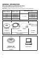
APPLICABLE MODELS AND NECESSARY TOOLS
The applicable models and necessary tools are as follows.
IMPORTANT: Numbers in "Necessary Tool" columns show the illustration number below.
MODEL NAME
NECESSARY TOOL
MODEL YEAR
for O2 Feedback
60/70
1998 and later
40/50
1999 and later
3 and 4 (A)
3 and 4 (B)
1, 2, 3, and 5
90/115
2002 and later
3 and 4 (C)
140
2002 and later
3 and 4 (D)
1
2
Compact Disc
Diagnostic Harness
Adapter
P/N 5033251
P/N 787053
P/N 5000002
4 Stroke Diagnostic
System software V 4.0
Cable and adapter kit – contains Diagnostic Harness and Adapter
O2 Sensor
4
5
P/N 5032458 – 40/50
P/N 5032478 – 60/70
P/N 5034161 – 90/115/140
Laptop Computer
Test Wheel
2
3
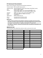
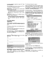
PC HARDWARE REQUIREMENTS
Make sure that the personal computer meets the following requirements.
Personal computer:
Operating system:
CPU:
Memory:
Hard disk:
Display:
Drive:
Interface port:
Mouse:
Printer:
IBM-compatible laptop computer
Microsoft Windows 95, Windows 98, Windows 2000 (English version)
Pentium 133MHz or higher
Windows 95/98: 32MB or more (recommended 64MB or more)
Windows 2000: 64MB or more (recommended 128MB or more)
20MB of free space or more (recommended 40MB or more)
SVGA (800 x 600 pixels, 65000 or more colors)
CD-ROM drive
RS232C (Dsub 9-pin) port
Compatible with the operating system
Compatible with the operating system
IMPORTANT:
• Program response and performance depends on the personal computer environment settings.
• The necessary memory capacity and hard disk capacity differ depending on the system environment. Also, running the program when there is very little free space on the hard disk may cause
the computer to run out of memory or experience other problems during operation.
• This program automatically tries to establish communication on a current communicable COM
port within port 1 and port 2. If necessary, set the serial port as specified in the instruction manual
of your computer.
ABBREVIATIONS
The following table shows abbreviations and terms which may be used in this manual.
ABBREVIATION
FULL TERM
ABBREVIATION
FULL TERM
CKP sensor
Crankshaft Position sensor
MB
Mega-Bytes
CMP sensor
Camshaft Position sensor
CC
Cubic centimeter
CPU
Central Processing Unit
MIN.
Minute(s)
CTP switch
Closed Throttle Position switch
NO.
Number
Cyl.
Cylinder
P/N.
Part Number
ECM
Engine Control Module
PORT
Port side
Ex.
Exhaust
RPM
Revolution Per Minute
HRS
Hour(s)
4SDS
4 Stroke Diagnostic System
IAC valve
Idle Air Control valve
Spec.
Specification
IAT sensor
Intake Air Temperature sensor
STBD
Starboard side
Info.
Information
Sys.
System
INJ
Injection
Temp.
Temperature
KB
Kilo-Bytes
µs
Micro-second
MAP sensor
Manifold Absolute Pressure sensor
3
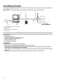
SYSTEM OUTLINE
A computer should be connected to the ECM of the outboard motor using the tools as shown below.
IMPORTANT: The 4SDS program should be installed on the computer's hard drive.
3
4
5
Outboard Motor
1
1.
2.
3.
4.
5.
2
4SDS Software version 4.00 P/N 5033251
Laptop computer
COM port
Cable and adapter kit P/N 787053
8-Pin coupler
In this system, communication between the ECM of the outboard motor and personal computer occurs
via the diagnostic harness and adapter. The following information is communicated from the ECM to
the computer:
• Engine information
• Current service (self-diagnostic) codes
• Real-time display of service data
• Engine operating history
• O2 feedback operation
IMPORTANT:
• Read this user’s guide before proceeding.
• Refer to the safety precaution indicated in the service manual.
• This software is designed for use with a battery-powered (DC-type) laptop personal computer. –
Do not use an AC-type personal computer
• This software may not operate on some personal computers with the operating environment
required.
• Always follow the explanations displayed in each screen, window, or dialog box.
4
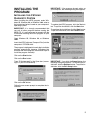
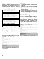
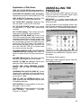
INSTALLING THE
PROGRAM
IMPORTANT: If the program already exists on
your computer, the following dialog box appears.
INSTALLING THE 4 STROKE
DIAGNOSTIC SYSTEM
When installing the 4SDS program under Windows 95, Windows 98, or Windows 2000, refer to
the instructions below, based on your computer's To update the 4SDS program, click the Yes butoperating system.
ton. To quit the installation, click the No button.
IMPORTANT: It is strongly recommended that To continue the installation, click the Next button.
you exit all other programs before running the To quit the installation, click the Cancel button.
4SDS CD. It is not necessary to connect with the
ECM when installing the 4SDS program on your
computer.
Open Windows 95, Windows 98, or Windows
2000.
Insert the 4SDS software (Compact Disc) into the
computer's CD-ROM drive.
The program is designed to launch the installation
program automatically, however, if Windows fails
to launch the install program, follow these steps to
install the program manually:
Click on the Start button.
Click on the Run button.
Type “D:\Autorun.exe” in the Open box (assum- IMPORTANT: If you click the Cancel button, the
ing D: is your CD ROM drive).
following dialog box appears. To continue the installation, click the Resume button. To quit the installation, click the Exit Setup button.
Click on the OK button.
Follow the on screen prompt to complete the installation.
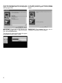
5
Check the target directory and the program group If the 4SDS installation is successfully finished,
name. Click the Next button to start copying the the following window appears. Click the Finish
4SDS program files.
button.
IMPORTANT: To go back to the previous win- IMPORTANT: The database files are also indow, click the Back button. To quit the installa- stalled by installing the 4SDS program.
tion, click the Cancel button.
The program will automatically load to the appropriate folder location on the C: drive.
6
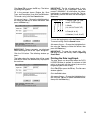
UPDATING THE DATABASE
The following screen appears.
When updating the database under the 4SDS,
adhere to the following instructions.
IMPORTANT:
• Before updating the database, make sure that
the 4SDS program has already been installed
on your computer.
• For updating the database, it is not necessary
to communicate with the ECM.
From the taskbar on the computer screen, click
the Start button and point to the Programs. Click
4 Stroke Diagnostic System to run the 4SDS program.
Press the Enter key to go to the next screen. The
following screen appears. Then press the Enter
key.
When the introduction screen appears, press the
Enter key.
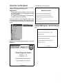
7
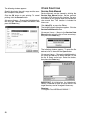
If there is no reply from the ECM, the following
window appears. Click the OK button. (KEYBOARD
USERS – Move to the OK button using the Up or
Down arrow keys, then press the Enter key.)
The following dialog box appears. Check if the
"Directory" indicates the computer's CD-ROM
drive. If not, click the T button in the "Drive" box
and select the CD-ROM drive. Select the 4SDS
folder, then the db folder.
To start overwriting the database files, click the
OK button.
To cancel overwriting, click the Cancel button.
(KEYBOARD USERS – Change the highlighted button using the Tab key. To select the item in the
box, use the Up or Down arrow keys. Select the
button, then press the Enter key.)
IMPORTANT: If there is a reply from the ECM,
the COMMUNICATION ERROR window will not
display.
Insert the 4SDS database disc (compact disc)
into the computer's CD-ROM drive.
IMPORTANT: All 4SDS database files existed
on the computer's hard drive are overwritten from
the database disk.
Click on File (F2) or press the F2 key. The following menu dialog box appears. Click the dialog box
button. (KEYBOARD USERS – Move to the Update
database button using the Up or Down arrow
If the updating database is successfully finished,
keys, then press the Enter key.)
the following dialog box appears.
IMPORTANT: If there is no database files available on the selected drive and folder, the following dialog box appears. Database files are
included on the CD if the manufacturer finds it
necessary. Electronic updates will be made available if required by the manufacturer.
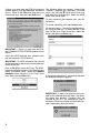
8
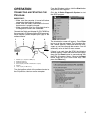
OPERATION
From the Windows taskbar, click the Start button
and point to the Programs.
CONNECTING AND STARTING THE
PROGRAM
Click the 4 Stroke Diagnostic System to start
the 4SDS program.
IMPORTANT:
• Make sure the computer is turned off before
connecting the diagnostic harness.
• Make sure the battery connected to the outboard motor is properly charged.
• Make sure none of the six single lead wires in
the diagnostic harness are connected.
Connect the Cable and Adapter Kit P/N 787053 to
the computer's COM port and the ECM communication coupler (round shaped 8-pin type) of the
outboard motor.
1
2
3
4
The introduction screen will appear. Press Enter
key to go to the next screen. The "Important Notice" screen appears. Read and follow the messages as you move through the screens. You will
eventually arrive at the first menu screen.
5
1.
2.
3.
4.
5.
6.
6
RS232C (To computer’s COM port)
Diagnostic harness
Six single lead wires
8-Pin coupler (to ECM communication coupler)
Adapter
1-Pin coupler (for O2 sensor)
If there is no reply from the ECM, the following
window appears. Read and follow the messages,
then click the Reset button to communicate with
the ECM. (KEYBOARD USERS – Move to the Reset
button using the Up or Down arrow keys, then
press the Enter key.)
Turn the ignition switch of the outboard motor to
the ON position, then turn on the computer
9
IMPORTANT: Once the first menu screen appears, the following dialog box appears if there
communication with the ECM is lost. Read and
follow the messages, then click the OK button to
retry communication with the ECM. (KEYBOARD
USERS – Press the Enter key.)
DATA LOGGER
Major service data can be displayed as a graph.
A maximum of three items can be logged at one
time and can be saved as ".csv" file format.
EXIT
The 4SDS program is exited.
CLOSE (ESC)
The menu box is closed.
Click the item button from the main menu window.
(KEYBOARD USERS – To change the highlighted
button, use the Up or Down arrow keys to select
the button, then press the Enter key.)
IMPORTANT: The SERVICE DATA, CURRENT
SERVICE CODES and ACTUATOR TEST windows can be displayed at one time. To change
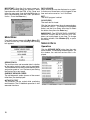
MAIN MENU
the active window, click Window (F4), or press
From the first menu screen, click Main Menu (F1) the F4 key.
or press the F1 key. The following menu dialog
box appears.
SERVICE DATA
Operation
Click the SERVICE DATA button from the main
menu window. The following window appears. On
this window, the real-time service data is displayed.
SERVICE DATA
The real-time data and recorded data in relation
to the engine control system can be monitored.
The monitored service data can be selected at will
and can be saved as ".csv" file format (see Saving
the Service Data, next page).
CURRENT SERVICE CODES
The self-diagnostic codes (names of the current
failed item) can be displayed.
ACTUATOR TEST
The actuators can be cycled while monitoring
real-time data. The O2 feedback operation is also
executed from here.
10
The five data item groups (Engine data, Caution
sys. info., Operation hours, O2 feedback info.,
and All service data) can be selected. Click the T
button and select the data item group. (KEYBOARD
USERS – Open the data item list group using the
Up or Down arrow keys. Select the item, then
press the Enter key.)
1
1. Data item group
The following dialog box appears. The items with
"√" marks are displayed. To change the status between "displayed" or "not displayed", click the
check box of the item, then click the OK button.
(KEYBOARD USERS – Change the selected item
using the Up or Down arrow keys. Use the Space
key to change the status between "displayed" or
"not displayed". Select the button with the Tab
key, then press the Enter key.)
IMPORTANT: Click the Cancel button to cancel
any changes.
IMPORTANT: To view the data item groups to Saving the Service Data
which each data item belongs, refer to Table of
All service data can be saved when the SERVICE
Data Item Groups.
DATA window is opened. Files saved in a “.csv”
To select the displayed items of each group, click format can be viewed using the 4SDS Program.
the Select button. (KEYBOARD USERS – Move to Other common Windows programs, such as Mithe Select button using the Tab key, then press crosoft Excel, WordPerfect, Windows Write, Mithe Enter key.)
crosoft Word, or Microsoft Access, will allow you
to view “.csv” files. Refer to the application’s user’s manual for more information.
11
Click Save (F3), or press the F3 key. The follow- Click the OK button. The following window aping dialog box appears. Type the correct informa- pears. This program automatically selects the
tion into the comment boxes (Engine No., Boat folder and file name.
Type, and Description), then click the OK button.
To cancel saving, click the Cancel button. (KEYBOARD USERS – Change the highlighted button
using the Tab key. Select the button, then press
the Enter key.)
IMPORTANT: The “Save As” window is configured during initialization. The target folder and the
file name can be changed, if necessary. By default, all service data is saved in the "DataList"
folder and named "DXXXXXXX".
Directory:
C:\Program Files\4SDS\DataList\DXXXXXXX.csv
IMPORTANT:
• The comment boxes are displayed when
selecting the file on the "Open" dialog box.
• The displayed data in the SERVICE DATA
window is fixed to save it when clicking
Save (F3) or pressing the F3 key.
D 070 4 24 8
1. Engine Type (i.e. “070”
means 70 PS engine)
2. Month
(1,2,3,4,5,6,7,8,9,X,Y,Z)
1
2 3 4
3. Date (01 to 31)
4. Number (1 to 9, A to Z)
To save all service data, click the Save button. To
cancel saving, click the Cancel button. (KEYBOARD USERS – Change the highlighted button
using the Tab key. Select the button, then press
the Enter key.)
12
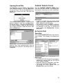
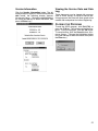
Opening Saved Data
CURRENT SERVICE CODES
Click File (F2), or press the F2 key. The following Click the CURRENT SERVICE CODES button
menu dialog box appears. Click the Open button. from the main menu window. The following win(KEYBOARD USERS – Move to the Open button us- dow appears, displaying any current failed items.
ing the Up or Down arrow keys, then press the
Enter key.)
The following window appears. To open the file
desired, highlight it, then click the Open button.
(KEYBOARD USERS – Change the highlighted button using the Tab key. Select the item using the
Up or Down arrow keys. Select the button, then
press the Enter key.)
IMPORTANT:
• If there is no failed item (no current service
code), "No failure" is displayed in the CURRENT SERVICE CODES window.
• The SERVICE DATA, CURRENT SERVICE
CODES and ACTUATOR TEST windows can
be displayed at one time. To change the
active window, click Window (F4), or press
the F4 key.
ACTUATOR TEST
Operation
Click the ACTUATOR TEST button from the main
menu window. The following two windows appear.
IMPORTANT: If the file has input comments (Engine No., Boat Type, and Description), they are
displayed next to the file list box when the file is
highlighted.
IMPORTANT:
• The SERVICE DATA (Engine Data) window is
automatically opened when the ACTUATOR
TEST window is opened.
• Read and follow the "Description" and "Message" in the ACTUATOR TEST window.
• To change the active window, click the
Window (F4) or press the F4 key.
13
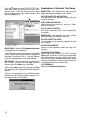
Click the T button in the ACTUATOR TEST win- Explanation of Actuator Test Items
dow, then select the actuator test item. (KEYBOARD USERS – Open the actuator test list using IMPORTANT: The following test items may be
the Up or Down arrow keys. Select the item, then performed when the engine is not running.
press the Enter key.)
#X FUEL INJECTOR ACTUATION:
Fuel injection for the specified cylinder will actu1
ate for 5 seconds.
FUEL PUMP ACTUATION:
High pressure fuel pump will actuate at 100%
duty for 5 seconds.
IAC VALVE ACTUATION:
IAC valve will actuate at 1Hz (1 time a second) for
5 seconds.
IMPORTANT: The following test items may be
performed when the engine is running.
#X FUEL INJECTOR STOP:
Fuel injection for the specified cylinder will stop
for 5 seconds.
1. Actuator test item
#X IGNITION MISFIRE:
Ignition for the specified cylinder will stop for 5
IMPORTANT: Refer to O2 Feedback Operation seconds.
if selecting the "O2 Feedback.”
FIXED IGNITION TIMING:
To perform the actuator test selected, click the Go Ignition timing will be fixed at 5° BTDC until the
button. The test takes approximately 5 seconds to Stop button is clicked. This test can be performed
complete. (KEYBOARD USERS – Use the Tab key when the engine is running. Perform this test for
to move to the Go button, then press Enter.)
the ignition system troubleshooting when idling.
The monitored ignition timing during actuation is
IMPORTANT: The performance of "Fixed Igni- a calculated value but not actual one.
tion Timing" continues until the Stop button is
clicked or until the Enter key is pressed.
O2 FEEDBACK:
Refer to O2 Feedback Operation.
Clicking the Stop button or pressing the Enter
key while the test is being performed will interrupt
the test.
If there is no response from the ECM during the
interruption, the following window appears. Follow the message in this window.
14
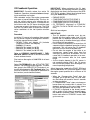
O2 Feedback Operation
IMPORTANT: When performing the O2 feedback operation, the following five items should be
IMPORTANT: Carefully review the entire O2 displayed at one time in the item box of the SERFeedback Operation procedure before attempt- VICE DATA window. Select the displayed items
using the Select button if necessary.
ing to recalibrate any engine.
After extended usage, the engine components • ENGINE SPEED
may wear or become deteriorated. This may im- • COMPENSATION FACTOR (ZONE 1)
pact the air/fuel mixture ratio, affecting the ex- • COMPENSATION FACTOR (ZONE 2)
haust emissions of the engine. To correct the air/ • COMPENSATION FACTOR (ZONE 3)
fuel mixture ratio, the O2 sensor should be used • O2 FEEDBACK (displayed as STAND-BY,
ACTION, FIN.OK or FIN.NG in the "Data" colto measure oxygen in the exhaust gas. The ECM
umn)
uses the O2 sensor data to correct the compensation coefficient of the fuel injection duration
Shift into forward gear.
map.
IMPORTANT:
Procedure
• The O2 feedback operation must be perInstall the O2 sensor to the engine, then connect
formed with the engine under load. Do not
the O2 sensor coupler to the diagnostic harness.
perform the O2 feedback operation using the
Install the appropriate test wheel.
warm-up lever (or throttle control grip) without
• 787053: Cable and Adapter Kit (Includes
first shifting into forward gear.
Diagnostic Harness and Adapter)
• Do not close the throttle fully for more than 10
• 5000002: O2 sensor
seconds while the feedback operation is being
• 5032478: Test wheel (for 60/70)
performed. This will cause the O2 feedback
• 5032458: Test wheel (for 40/50)
operation to finish with incomplete data.
• 5034161: Test wheel (for 90/115/140)
• Do not allow the engine to be stable at an
unnecessary speed range (other than the
Refer to PERIODIC MAINTENANCE / FUEL
zone rpm) for more than 10 seconds. This will
MIXTURE CHECK section in the service manual
cause the O2 feedback operation to be comof each outboard motor.
pleted with incorrect data for that speed
range.
Start and run the engine at 2000 RPM for at least
•
As the zirconia element in the O2 sensor is
5 minutes.
not conductive below 250°C, the O2 sensor
will not function properly until the engine is at
Select O2 FEEDBACK in the ACTUATOR TEST
normal operating temperature.
window. The following window appears. The data
item group in the SERVICE DATA window is automatically changed to O2 Feedback Info. Con- Adjust the engine speed at the ZONE1 RPM and
firm that STAND-BY is displayed in the bottom of click the Go button. ACTION mode appears. Hold
the engine speed specified for a minimum of 20
the item box (see circled data below).
seconds.
• When the “Compensation Factor” data has
changed, go to the next step. For tiller models, the buzzer will sound for about 2 seconds
on step completion.
• If “Compensation Factor” does not change or
buzzer does not sound within 2 minutes, the
feedback operation at this zone failed. Ignore
this zone and proceed to the next step.
• If FIN.NG is displayed or the buzzer sounds
with a series of long (about 2 second) beeps,
the feedback operation failed. Click the Stop
button and revert to STAND-BY mode, then
go to next step.
15
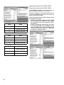
Repeat the procedure at the ZONE 2 RPM.
Repeat the procedure at the ZONE 3 RPM.
If the feedback operation at any zone failed, repeat the feedback operation at that zone
Return the throttle to a full closed position only after the O2 feedback operation at all zones has
been successfully finished.
16
ZONE
40/50
1
2500 ± 100 RPM
2
3500 ± 100 RPM
3
4500 ± 100 RPM
ZONE
60/70
1
2000 ± 100 RPM
2
3000 ± 100 RPM
3
4000 ± 100 RPM
ZONE
90/115/140
1
2000 ± 100 RPM
2
3000 ± 100 RPM
3
4000 ± 100 RPM
About 10 seconds after closing the throttle, one of
the following will appear:
• FIN.OK is displayed, indicating the total feedback operation was successful. Tiller models
will sound the buzzer for 0.5 seconds, indicating success.
• FIN.NG is displayed, indicating the total feedback operation failed. Click the Stop button to
revert to STAND-BY mode. Tiller models will
sound the buzzer with a series of long beeps
(2 seconds), indicating failure.
If retrying feedback operation, repeat O2 Feed- The following dialog box appears.
back procedures.
Input the sampling cycle and the logging time,
Click the Stop button before closing the ACTUA- then select the items. The items with “√" marks
are displayed. To change the status between
TOR TEST (O2 feedback) window.
"displayed" or "not displayed", click the check box
IMPORTANT: The following may cause the total of the item. Then click the OK button.
feedback operation to fail:
• No feedback operation at any zone before (KEYBOARD USERS – Change the highlighted button using the Tab key. The selected item can be
returning the throttle to a full closed position.
• An abnormal compensation factor (coeffi- changed using the Up or Down arrow keys. Use
the Space key to change the status between "discient).
played" or "not displayed". Select the button, then
IMPORTANT: Repeat the O2 feedback opera- press the Enter key.
tion with a new O2 sensor if:
• The total feedback operation finished without
returning the throttle to a full closed position.
• The total feedback operation failed repeatedly.
LOGGING DATA
Operation
Click the DATA LOGGER button from the main
menu window. The DATA LOGGER window appears.
A maximum of three items can be displayed as a
graph at one time.
To select the item and change the sampling condition, click the Setup button.
(KEYBOARD USERS – Change the highlighted button using the Tab key. Move to the Setup button,
then press the Enter key.
1
IMPORTANT: If the input condition is incorrect or
no item is selected, the following dialog box appears. Click the OK button, then repeat the procedure.
To start monitoring the data as a graph, click the
Monitor button.
To stop monitoring, click the Stop button.
1. Current condition
(KEYBOARD USERS – Change the highlighted button using the Tab key to select the button, then
press the Enter key.)
IMPORTANT: The other window (SERVICE DATA, CURRENT SERVICE CODES, or ACTUATOR TEST) opened on the screen is IMPORTANT: The Stop button is available only
automatically closed when the DATA LOGGER while monitoring or logging the data.
window is opened.
17
On the graphs for the following fourteen items, the IMPORTANT:
numbers on the vertical axis show the number of • The Go button is available only while monitoring the data.
times counted since opening the current DATA
LOGGER window, but not the total number of • A maximum of most recent 100 points in the
graph can be displayed on the screen. The
times. The number of times is returned to zero (0)
horizontal axis is automatically scrolled to the
every start of logging (or monitoring).
left if the points of the logging (or monitoring)
data over 100 points.
1. NO. OF MAP SENSOR FAILURE
• A point on the horizontal axis means a elapse
2. NO. OF CKP SENSOR FAILURE
of logging (or monitoring) time. For example,
in case that "0.5 sec" is input as the sampling
3. NO. OF IAC VALVE FAILURE
cycle, 100 points show 50 seconds.
4. NO. OF CMP SENSOR FAILURE
5. NO. OF CTP SWITCH FAILURE
Saving the Data Log
6. NO. OF CYL TEMP. SNSR FAILURE
Data can be saved only after the process has
completely finished. Files saved in a “.csv” format
7. NO. OF IAT SENSOR FAILURE
can be viewed using the 4SDS Program. Other
8. NO. OF EX. TEMP. SNSR FAILURE
common Windows programs, such as Microsoft
9. NO. OF FUEL INJECTOR FAILURE
Excel, WordPerfect, Windows Write, Microsoft
Word, or Microsoft Access, will allow you to view
10. NO. OF OVER-REVOLUTION
“.csv files. Refer to the application’s user’s manu11. NO. OF LOW BATTERY VOLTAGE
al for more information.
12. NO. OF LOW OIL PRESSURE
13. NO. OF OVERHEAT (GRADIENT)
14. NO. OF OVERHEAT (TEMP.)
To start logging the data, click the Go button. The
logging is automatically finished in the logging
time input.
To stop logging, click the Stop button.
(KEYBOARD USERS – Change the highlighted button using the Tab key to select the button, then
press the Enter key.)
1
1. Elapsed logging time
2. Total logging time
18
2
Click Save (F3), or press the F3 key. The follow- IMPORTANT: The file of logging data is autoing dialog box appears.
matically saved in the "DataGraph" folder and
named "LXXXXXXX". At initialization, the followFill in the comment boxes (Engine No., Boat ing directory is selected to save the file. The tarType, and Description), then click the OK button. get directory and the file name can be changed if
To cancel saving, click the Cancel button.
necessary.
(KEYBOARD USERS – Change the highlighted button using the Tab key to select the button, then
L 070 4 24 8
1. Engine Type (i.e. “070”
press the Enter key.)
means 70 PS engine)
2. Month
(1,2,3,4,5,6,7,8,9,X,Y,Z)
1
2 3 4
3. Date (01 to 31)
4. Number (1 to 9, A to Z)
To save the logging data, click the Save button.
To cancel saving, click the Cancel button.
(KEYBOARD USERS – Change the highlighted button using the Tab key to select the button, then
press the Enter key.)
IMPORTANT: These comments are displayed
when selecting the file on the "Open" dialog box. IMPORTANT: To open the saved data, click
File (F2) or press the F2 key. Refer to Opening
Click the OK button. The following window apSaved Data.
pears.
The folder where the logging data will be saved Printing the Data Log/Graph
and the file name are automatically displayed in
The data graph can be printed when the DATA
the each box.
LOGGER window is opened. A maximum of 100
points in the graph can be printed (same as the
range displayed on the screen).
Click File (F2) or press the F2 key. The file menu
window appears.
Click the Print button.
(KEYBOARD USERS – Change the highlighted button using the Tab key to select the Print button,
then press the Enter key.)
19
The following window appears.
OTHER FUNCTIONS
Specify the printer, the print range and the number of copies to be printed.
Service Data Manual
Service Manuals can be viewed by clicking the
Click the OK button to start printing. To cancel Service Data Manual button. Service manuals
must be in PDF format for this function. The origprinting, click the Cancel button.
inal release of this program does not include ser(KEYBOARD USERS – Change the highlighted but- vice manual files. This function is included for
ton using the Tab key to select the button, then future use.
press the Enter key.)
Click Help (F9), or press the F9 key.
The following menu dialog box appears. Click the
Service Data Manual button.
(KEYBOARD USERS – Move to the Service Data
Manual button using the Up or Down arrow keys,
then press the Enter key.)
The following window appears. To open the file
desired, click it, then click the Open button.
(KEYBOARD USERS – Change the highlighted button using the Tab key to select the item, or use
the Up or Down arrow keys. Select the button,
then press the Enter key.)
IMPORTANT: At initialization, the following directory is selected to open (or save) the file. The
target directory can be changed if necessary.
Directory:
C:\Program Files\4SDS\Info\XXXXXX.***
20
Version Information
Click the Version information button. The following dialog box appears. When clicking the Details button, the following window appears.
(KEYBOARD USERS – Change the highlighted button using the Tab key to select the button, then
press the Enter key.)
Viewing the Service Data and Data
Log
These documents can be viewed with programs
such as Excel, Access, or Write to name a few.
Using programs like Excel will allow graphs to be
created and manipulated for further diagnosing.
CLOSING THE PROGRAM
To end the 4SDS program, click Exit (F10), or
press the F10 key. The following dialog box appears. To exit the program, click the OK button.
To cancel exiting, click the Cancel button. (KEYBOARD USERS – Change the highlighted button
using the Tab key to select the button, then press
the Enter key.)
21
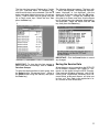
DATA ITEM GROUPS
Table of Data Item Groups
The following tables shows the groups to which each data item belongs. The items with "X" marks can
be displayed and can be selected at will within the items marked "X".
Group No. 1:
Group No. 2:
Group No. 3:
Group No. 4:
Group No. 5:
Group No. 6:
Engine Data (available items in the "SERVICE DATA" function)
Caution Sys. Info. (available items in the "SERVICE DATA" function)
Operation Hours (available items in the "SERVICE DATA" function)
O2 Feedback Info. (available items in the "SERVICE DATA" function)
All Service Data (available items in the "SERVICE DATA" function)
Data Logger (available items in the "DATA LOGGER" function)
DATA ITEM
ENGINE SPEED
IGNITION TIMING
MANIFOLD ABSOLUTE PRESSURE
MANIFOLD ABSOLUTE PRESSURE
MANIFOLD ABSOLUTE PRESSURE
BAROMETRIC PRESSURE
BAROMETRIC PRESSURE
BAROMETRIC PRESSURE
CYLINDER TEMPERATURE
CYLINDER TEMPERATURE
INTAKE AIR TEMPERATURE
INTAKE AIR TEMPERATURE
BATTERY VOLTAGE
FUEL INJ. PULSE WIDTH
INJECTED FUEL AMOUNT
FUEL PUMP DUTY
IAC VALVE DUTY
NO. OF MAP SENSOR FAILURE
NO. OF CKP SENSOR FAILURE
NO. OF IAC VALVE FAILURE
NO. OF CMP SENSOR FAILURE
NO. OF CTP SWITCH FAILURE
NO. OF CYL. TEMP. SNSR FAILURE
NO. OF IAT SENSOR FAILURE
NO. OF EX. TEMP. SNSR FAILURE
NO. OF FUEL INJECTOR FAILURE
NO. OF OVER-REVOLUTION
NO. OF LOW BATTERY VOLTAGE
NO. OF LOW OIL PRESSURE
NO. OF OVERHEAT(GRADIENT)
NO. OF OVERHEAT(TEMP.)
CAUTION SYSTEM NAME (1)
ENGINE SPEED (1)
MANIFOLD ABSOLUTE PRESSURE (1)
MANIFOLD ABSOLUTE PRESSURE (1)
MANIFOLD ABSOLUTE PRESSURE (1)
CYLINDER TEMPERATURE (1)
CYLINDER TEMPERATURE (1)
INTAKE AIR TEMPERATURE (1)
INTAKE AIR TEMPERATURE (1)
EX-MANI TEMPERATURE (1)
EX-MANI TEMPERATURE (1)
FAILURE TIME (1)
ELAPSE OF TIME (1)
CAUTION SYSTEM NAME (2)
ENGINE SPEED (2)
22
Unit
rpm
°
mmHg
kPa
inHg
mmHg
kPa
inHg
°C
°F
°C
°F
V
µs
mcc
%
%
times
times
times
times
times
times
times
times
times
times
times
times
times
times
rpm
mmHg
kPa
inHg
°C
°F
°C
°F
°C
°F
h
min
rpm
1
X
X
X
X
X
X
X
X
X
X
X
X
X
X
X
X
X
GROUP NO.
3 4 5
X X
X
X X
X X
X X
X
X
X
X X
X X
X
X
X
X
X
X
X
X
X
X
X
X
X
X
X
X
X
X
X
X
X
X
X
X
X
X
X
X
X
X
X
X
X
X
X
X
X
X
X
X
X
X
X
X
X
X
X
X
X
X
X
X
X
X
X
X
X
X
X
X
X
X
X
X
X
2
DATA ITEM
6
X
X
X
X
X
X
X
X
X
X
X
X
X
X
X
X
X
X
X
X
X
X
X
X
X
X
X
X
X
X
X
MANIFOLD ABSOLUTE PRESSURE (2)
MANIFOLD ABSOLUTE PRESSURE (2)
MANIFOLD ABSOLUTE PRESSURE (2)
CYLINDER TEMPERATURE (2)
CYLINDER TEMPERATURE (2)
INTAKE AIR TEMPERATURE (2)
INTAKE AIR TEMPERATURE (2)
EX-MANI TEMPERATURE (2)
EX-MANI TEMPERATURE (2)
FAILURE TIME (2)
ELAPSE OF TIME (2)
CAUTION SYSTEM NAME (3)
ENGINE SPEED (3)
MANIFOLD ABSOLUTE PRESSURE (3)
MANIFOLD ABSOLUTE PRESSURE (3)
MANIFOLD ABSOLUTE PRESSURE (3)
CYLINDER TEMPERATURE (3)
CYLINDER TEMPERATURE (3)
INTAKE AIR TEMPERATURE (3)
INTAKE AIR TEMPERATURE (3)
EX-MANI TEMPERATURE (3)
EX-MANI TEMPERATURE (3)
FAILURE TIME (3)
ELAPSE OF TIME (3)
TOTAL OPERATION TIME (HRS.)
TOTAL OPERATION TIME (MIN.)
0-1000 RPM
1000-2000 RPM
2000-3000 RPM
3000-4000 RPM
4000-5000 RPM
5000-6000 RPM (*)
ABOVE 5000 RPM
ABOVE 6000 RPM (*)
ELAPSE TIME FROM REMINDER CANCEL
NO. OF OIL CHANGE REMINDER
COMPENSATION FACTOR (ZONE 1)
COMPENSATION FACTOR (ZONE 2)
COMPENSATION FACTOR (ZONE 3)
TIME OF LAST O2 FEEDBACK
EMERGENCY STOP SWITCH
CTP SWITCH
NEUTRAL SWITCH
O2 FEEDBACK
Unit
mmHg
kPa
inHg
°C
°F
°C
°F
°C
°F
h
min
1
rpm
mmHg
kPa
inHg
°C
°F
°C
°F
°C
°F
h
min
h
min
min
min
min
min
min
min
min
min
h
times
h
X
X
X
* These items are available only for the 40/50 and 140.
GROUP NO.
2 3 4 5
X
X
X
X
X
X
X
X
X
X
X
X
X
X
X
X
X
X
X
X
X
X
X
X
X
X
X
X
X
X
X
X
X
X
X
X
X
X
X
X
X
X
X
X
X
X
X
X
X X X
X X X
X
X
X
X
X
X
X
X
X
X
X
X
X
X
X
X
X
X
X
X
X X
X X
X X
X X
X
X
X
X
6
X
X
X
Explanation of Data Items
FUEL INJ. PULSE WIDTH (micro-second): Injection time duration for each cylinder per 1 time.
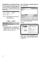
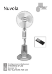
UNINSTALLING THE
PROGRAM
INJECTED FUEL AMOUNT (cubic centimeter): When uninstalling the 4SDS program from your
Injected fuel amount for each cylinder per 1 time. computer, refer to the instructions below, based
on your computer's operating system.
FUEL PUMP DUTY (percent): Repeating "ON"
IMPORTANT: It is strongly recommended that
time rate within a cycle for fuel pump drive.
you exit all other programs before running the
IAC VALVE DUTY (percent): Repeating "ON" 4SDS uninstaller.
time rate within a cycle for IAC valve drive.
From the taskbar on your computer screen, click
NO. OF XXXX FAILURE (times): Total number the Start button and point to the Setting, then click
of abnormality in a signal from sensor/switch the Control Panel. The following window appears.
specified.
NO. OF XXXX (times): Total number of the activation for the CAUTION system specified.
CAUTION SYSTEM NAME (X): Name of the
CAUTION system activated. (indicating the latest,
2nd-latest, and 3rd-latest activation except for the
"OVER-REVOLUTION) Its following items with
the same number (X) are the main data when activating that CAUTION system. The number (X)
does not mean the order of system activation. Refer to the "FAILURE TIME (X)" to confirm when
the system activation occurred.
CYLINDER TEMPERATURE (X) & INTAKE AIR
TEMPERATURE (X): Indicated "-50°C (-58°F)" if
there is no record of the CAUTION system activa- Double-click the Add/Remove Programs icon in
the window.
tion.
FAILURE TIME (X) (hour): Total motor operating The following window appears.
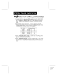
time when activating the CAUTION system.
Select the 4 Stroke Diagnostic System, then click
ELAPSE OF TIME (X) (minute): Elapsed time the Add/Remove button.
during the CAUTION system activation.
ELAPSE TIME FROM REMINDER CANCEL
(hours): Does not apply to Evinrude/Johnson
product.
COMPENSATION FACTOR (ZONE X): Current
compensation coefficient of the fuel injection duration map for each RPM zone specified. These
are initially all "1.000".
TIME OF LAST O2 FEEDBACK (hour): Total
motor operating time when performing the latest
O2 feedback operation.
XXXX SWITCH: Current condition for the specified switch. ("ON" or "OFF")
O2 FEEDBACK: Current condition for O2 feedback operation. ("STAND-BY", "ACTION",
"FIN.OK", or "FIN.NG")
23
The following dialog box appears. To uninstall the
4SDS program, click OK button. To quit uninstalling, click the Cancel button.
Click the OK button.
24
NOTES
25
4Diagnostic Software
Stroke
User's Guide
*5033250*
DSS02160I