1
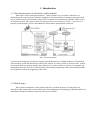
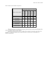
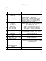
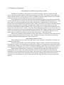
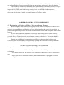
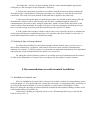
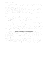
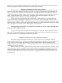
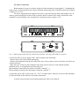
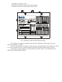
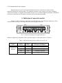
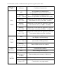
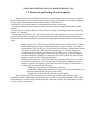
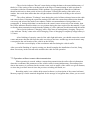
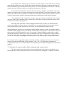
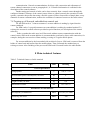
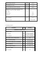
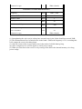
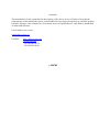
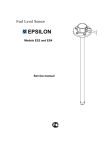
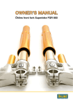
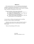
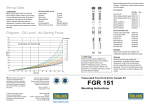
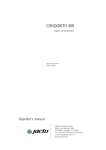
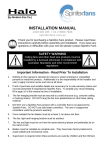
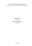
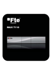
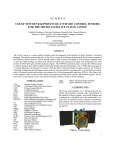
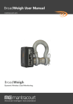
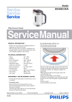
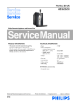
TELETRACK
INFORMATION AND CONTROL SYSTEM OF TRANSPORT NAVIGATION
Subscriber radio terminal of system Teletrack
Service manual
1
Contents
....................................................................................................................................................................
1 INTRODUCTION ............................................................................................................................... 2
1.1 TOTAL CHARACTERISTIC................................................................................................................................................. 2
1.2 MODELS RANGE ............................................................................................................................................................. 2
2 DELIVERY SET ................................................................................................................................. 4
2.1 MAIN SET ...................................................................................................................................................................... 4
2.2 ACCESSORIES ................................................................................................................................................................. 5
3 MAIN INFORMATION ON CONTROL UNIT .............................................................................. 6
3.1 FUNCTIONALITY ............................................................................................................................................................. 6
3.2 PRINCIPLES OF OPERATION ............................................................................................................................................. 7
3.3 GENERAL RECOMMENDATIONS OF USE ........................................................................................................................... 9
4 ORDER OF CONTROL UNIT COMMISSIONING .................................................................... 10
4.1 REGISTRATION AND SETTING OF MODE OF DATA RECORDING IN MEMORY ............................................................... 10
4.2 SETTING OF DATA EXCHANGE CHANNEL....................................................................................................................... 11
5 RECOMMENDATIONS ON RADIO TERMINAL INSTALLATION ...................................... 11
5.1 INSTALLATION OF CONTROL UNIT ................................................................................................................................ 11
5.2 SIM CARD INSTALLATION ............................................................................................................................................. 13
5.3 INSTALLATION AND CONNECTION OF AERIALS ............................................................................................................. 13
5.5 SOURCE CONNECTION .................................................................................................................................................. 15
5.6 CONNECTION OF WIRE SENSORS ................................................................................................................................... 17
6 INDICATION OF OPERATION MODES .................................................................................... 17
7 MAIN RECOMMENDATIONS OF RADIO TERMINAL USE ................................................. 19
7.1 FIRST START AND TESTING OF WORK CAPACITY ........................................................................................................... 19
7.2 OPERATION WITHOUT REMOTE DATA TRANSMISSION .................................................................................................. 20
7.3 OPERATION IN REMOTE MODE OF DATA EXCHANGE WITH CONTROL CENTER ............................................................... 21
7.4 TOPPING UP OF SIM CARD, EMBEDDED INTO CONTROL UNIT ........................................................................................ 22
8 MAIN TECHNICAL FEATURES .................................................................................................. 23
2
1. Introduction
1.1 Total characteristics of subscriber’s radio terminal
Subscriber’s radio terminal (hereinafter – radio terminal) is a part of the on-board set of
information and control system Teletrack, designed for solving problems of transport navigation with
use of satellite system of coordinates setting GPS. On-board set communicates with the control center
of Teletrack system. The control center can operate with several board sets. On Pic. 1 you can see a
general system structure, sources and channels of information transmission are shown.
Pic.1. System structure
Control unit is designed for collection, storage and transmission by available channels of information
about location, speed and direction of traffic of the vehicle. It is also possible to connect to the control
unit sensors that can remotely monitor the conditions of various systems of vehicles, for example, get
information about the fuel level in the fuel tank, about filling of passenger cabin, the switching on and
off of ignition or about the triggering of the alarm.
1.2 Models range
Due to block architecture of the product and also to module structure of control unit, the
subscriber radio terminal has a wide model range from minimum to full packaging. Marking and list of
manufactured models and their composition are given in Table 1.
Subscriber radio terminal
Table1. Radio terminal models composition.
Name of unit, module
ТТ2- 01
ТТ2- 03
ТТ2-21
ТТ2-23
ТТ2-25
Marking and composition of model
Controller module
●
●
●
●
●
GPS Module
●
●
●
●
●
●
●
GSM Module
●
GSM-М Module
●
ISM Module
Sensors module
●
●
●
●
●
●
During the operation according to the customer wish the model of radio terminal bought earlier
can be re-completed with necessary modules.
During the warranty period to preserve rights of the consumer for warranty repair and service
installation of additional modules to the control unit must be carried out by a representative of
hardware manufacturer.
2. Delivery set
2.1 Main set
Table 2.1. Composition of main set of subsсriber radio terminal.
№
Name
Quantity
Notes
1
Control unit
1
Model is selected according to costumer’s
requirements (see Table 1)
2
Aerial GSM/GPS,
type SA80-SMAM-5
1
combined, fastening ― adhesive basis,
disk Ø50×17 mm; is included to the set of models
ТТ2-21, ТТ2-23, ТТ2-25; in agreement with the
customer the change to aerial of another type from
accessories set is possible (see Table. 3)
3
Aerial GPS,
type HAG-130
1
magnetic retainer, 45×45×14,6 mm; is included to the
set of models ТТ2-01, ТТ2-03
4
Aerial feeders:
SMA male/female
MCX male/female
1
1
length 3,5 m; for connection of GSM aerial,
length 3,5 m; for connection of GPS aerial;
possible supply of feeders of required length
5
Radio modem aerial
SA10-SMBR-316-0.5
1
Is included to the set of models ТТ2-01, ТТ2-03
1
Length 2 m, safety fuse 3А
2
Safety fuse 1А
1 set
For radio terminal setting
6
7
8
Power cable
Spare set of
fuses
Fixing set:
Screw 3,9×19 – 4 pcs
Screw’s nut- 4 pcs
9
Set of connectors:
Connector 4- contacts
Connector 8- contacts
Connector 10-contacts
contacts
10
Card of sensor’s module
connection
1
―
11
Form
1
―
1
1
1
22
for connection of sensors to radio terminal, is included
to the set of all models
2.2 Accessories
Table 3. Accessories list
№
Name
Note
1
Aerial GSM/GPS,
type HАG-CDA
combined, fastening «for a nut», ellipse 50×60×15mm and pin 60
mm, for operation in conditions of GSM network unreliable
coverage
2
Aerial GSM/GPS,
type HGD-2
combined, fastening «for a nut», hemisphere
Ø100×30 mm; for operation in rough conditions
3
Aerial GSM/GPS,
type HGD-4
combined, bodiless for hidden placement 100×80×10mm
4
Aerial GPS,
type HAG-100
magnetic retain, disk Ø50×15 mm
5
Aerial GPS,
type HAG-100-GM
fastening ― adhesive basis, disk Ø50×15 mm
6
Aerial GPS,
type HAG-PSP2
Retain «for a nut», ellipse 50×60×15 mm
7
Radio modem aerial
SA10-SMBR-316-0.5
Ensures the operation of the radio modem’s module
8
Aerial feeders
length 3,5m or by order
9
HAG-130 bracket
Anti vandal aerial retainer HAG-130
10
Wire sensors
Uses together with sensors module
11
Power cable
length 2m, 4m, 6m or by order
12
Insulating
stabilizer BPS6
3. Main Information on Control Unit
3.1 Functionality
Determination of coordinates and parameters of vehicle traffic on the basis of satellite
navigation GPS system signals usage.
Data storage in nonvolatile memory.
Remote data exchange with the control center by available channels of communication,
resourced by mobile network standard GSM, the combination of resources GSM and
INTERNET and radio modem connection with control center workstation.
Exchanging data on a direct cable connection with a workstation of control center.
Data recording of data in nonvolatile memory and/or remote transmission of it to control center
in the following cases:
- expiration of the specified time interval (periodically repeating event),
- replacement at a given distance,
- crossing the control zone border,
- sensor’s alarm etc.
Formation of the data sampling using a flexible system of filters and transmission by the
specified channel according to request of control center.
Data transmission in encrypted form.
LED indication of
- probability of determining coordinates and traffic parameters by GPS data,
- device efficiency in GSM network and the signal level of the base station,
- activating of data exchanging with control center,
- activating of data recording in nonvolatile memory
- battery service.
3.2 Principles of operation
Determination of coordinates and parameters of traffic
Definition of coordinates and parameters of trafficis made by a built-in control unit GPS
receiver that uses satellite signals of global positioning system (GPS). The system is all-weather one
and provides the ability of receiving of accurate coordinates and time within 24-hours a day. Satellite
signals are taken by external GPS aerial connected to the control unit.
At the first start of control unit, and start after prolonged storage or power disconnection GPS
receiver may take up to 2.5 minutes for the issue of accurate coordinates and traffic parameters - "cold
start" mode. It is concerned with the need of data collection for synchronization of GPS receiver
internal clock and coordinates determination. After a short power failure or absence of satellite signals
because of screening effect of buildings and structures during vehicle traffic) GPS receiver uses
previously obtained data at the beginning. That’s why for recovery of reliable data issuing mode will
need to take some time near 2 seconds - "hot start" mode. During disconnection of power in time to 15
minutes or interruption of receiving information from satellites (for example, because of the screening
effect of the metal structure, under which the vehicle moved in for several hours) GPS receiver to
update mode of reliable data issuance will take up to 30 seconds - "warm start" mode.
Data about coordinates and parameters of the vehicle traffic is recorded to nonvolatile memory
of radio terminal and transmitted to control center. Software of control center allows customizing
recording and data transmission modes of the control unit.
Data exchange with control center
Data exchange between control unit and control centre should be accomplished in distance or
with help of cable joint.
At direct cable joint the control unit with help of special interface and cable 2m long through
the connector «UART» the control unit is connected to СОМ port of workstation of the control centre.
At distant data exchange one of accessible connection channels is used They are secured by resources
of GSM network, combination of resources of GSM and INTERNET or radio modem connection.
Radio modem channel allows realizing the exchange data in radius near 100m from work
station of the control centre. This method provides presence of radio modem in control unit and
installation of corresponding aerial on the vehicle, and connection of radio modem with an aerial to the
work station of the control center. Method of data exchange with help radio modem connection is
considered to be an alternative to direct cable connection for read-out of data, stored in control unit
memory.
In this case it is not necessary to deinstall the control unit from the vehicle.
To receive information about vehicle traffic in real the channel data exchange channels are
used. They are supported by GSM network and combination of «GSM + INTERNET». For realization
of any of these methods the control unit must include GSM module and an aerial.
In the first case, when only GSM network resources are used, data is transmitted by means
short text messages (classic SMS). To implement this method, the workstation of control unit must be
equipped with a GSM modem.
In the second case, when GSM and INTERNET resources are used, it is possible to realize data
transmission in two ways at least. The first one is based on the possibility of sending SMS with help of
e-mail control unit, as well as receiving e-mails in the form of SMS sent from the control station
connected to the INTERNET. This method can be called «E-mail via SMS». The second method is
based on the GSM network providing services for direct access to mail servers in the INTERNET
using GPRS or CSD. Control software provides support for such access. This method can be called
«E-mail via GPRS / CSD». Control station in this case should have access to the INTERNET for
sending and receiving e-mail.
The most prospective in terms of saving real time and save money is to transfer data using the
«E-mail via GPRS».
3.3 General recommendations on use
Power supply
Control unit gets power from the car electrical system or from other vehicle with a rated
voltage of 12 or 24 V direct current. The device has built-in pulse transformer, so ensures efficiency by
changing the voltage supply in range 10.8 ... 32 V. Maximum voltage consumption in this case varies
in the range from 0.50 to 0.15 A, accordingly. To ensure uninterrupted power in the control unit backup battery is installed. Work hours from built-in battery in the standard settings from 4 to 8 hours
during driving and 12 to 24 hours while parked.
Registration
To be able to communicate with control center control unit must be registered in a database
control center. Registration is done only by direct cable connection to a workstation controller.
Therefore, the registration is recommended to run the installation of radio in the vehicle.
Parameters setting
Software of control center provides a set of tools for effective control and changing of
parameters of control unit configuration. However, to obtain remote access to device control and
reading of data which is stored in it memory, it is necessary after registration using a direct cable
connection set up at least one channel of remote communication.
Choosing place for installation
To prevent possible damage or unauthorized disconnection of control unit it is recommended to
install it in protected from unauthorized access place. After connecting of aerials and power cable the
connectors are placed in two side protective coverers which are fixed with screws on the body
and sealing. The device must be protected from dirt and moisture, and not to be forced by heating.
The probability of data received from of radio, and reliability of information channels is largely
depends from the proper choice of aerials installation. The main supplying set of radio includes
integrated GPS / GSM aerial with bracing on sticky basis. For different conditions another
construction of aerial from accessories set may be more appropriate. For advice on the optimal
placement and selection of aerials you should contact the hardware vendor.
4 ORDER OF CONTROL UNIT COMMISSIONING
4.1 Registration and Setting of Mode of data recording in Memory
Before using the control unit must be registered in the database workstation of control center.
Due to the fact that registration is possible only by direct cable connection of device to the control
station, it is recommended to perform this procedure before installing the control unit to vehicle. To
perform the registration procedure you should read the relevant section in the description of the control
software.
In case if the control unit intended to be used only when writing data in volatile memory,
followed by reading all the stored information via a direct cable connection or radio modemconnection
you need after the registration set the record data in a memory of the device. This setting should be
done in case of necessity of remote data channel exchange between control center and control unit.
Despite the possibility of remote settings, performance of the procedure by direct cable
connection on the registration step will significantly speed up the verification of radio performance
after installation to the vehicle.
The order of registration and setting up of record data mode
1.Prepare the control unit and control software for using Direct cable connection mode:
- Connect an interface cable from the dispatcher’s set to a free COM port of control center
workstation.
- You should connect the free interface cable connector to the socket «UART» of the control
unit.
- Apply power to the control unit following the recommendations of paragraph 5.5 of this
maintenance guide.
- Set dispatcher’s software for data exchange with the control unit through the appropriate
COM port (see the description of the dispatcher’s software).
2. Perform the registration procedure in accordance with the instructions which contains the
description of the control software. During the procedure you will have to enter the ID code of the
control unit. The value of ID code marked on the label that is applied to the units body.
3. After successful performing of registration procedure you should perform tuning of the the
desired mode of data records to radio memory and also their sending through the channel of
communication with control center, using the instruction, which is located in the description of the
control software. Recommended for testing of the device efficiency during the checking period you
have to set data writing to memory and their transferring with a period of 1 minute.
4. If the remote data exchange with the control center is not expected you have to complete the
set by turning off the power and disconnecting of the interface cable from of radio. For the case of
remote data transmission you have to continue the tuning.
4.2 Setting of data exchange channel
To ensure the possibility of remote data exchange with the control center you have to use a
direct cable connection to a registered radio and set at least one of the possible communication
channels (see section 3.2). This procedure is recommended to implement immediately after registration
and setting the record and data transmission modes (see section 4.1).
For tuning the selected channel you have to record the necessary information into the memory
of radio and to the database of control center according to the description of control software.
5. Recommendations on radio terminal installation
5.1 Installation of control unit
Place for installation of control unit is selected in accordance with the recommendations set out
in the paragraph 3.3. You should take into account the convenience of connecting cables, possibility of
accessing to the SIM card holder, as well as possibility of visual control LED display of radio.
Moreover, during the choosing of location should be considered unacceptable bending of cables aerial
with rounded radius of less than 5 sm.
Control unit is holding on with help of four screws. Themounting holes are provided in the
body of unit (see Pic. 2).
Pic. 2. Top view, dimensions and mounting holes in body subscriber radio terminal Teletrack.
5.2 SIM card installation
Installation and obtaining of SIM card may be performed only after turning off the main and backup
power of radio.
For installation of SIM card you should make the next steps:
- Through the hole in the wall of the shell with help of thin core push the button-pusher, which is
located near the SIM card holder (see Figure 3), the holder must release the tape for the SIM card and
partly push her out from the body of the unit.
- Remove the cartridge and set to it the SIM card, contacts to the top.
- Insert the cassette with the installed SIM card back to holder until it stops; cassette should be fixed in
the holder.
5.3 Installation and Connection of aerials
During stretching of the aerial cable and connecting of it to the radio you shouldn’t avoid:
- Clamping of the cable
- putting cable between the moving parts of the body of the vehicle,
- Cable bends with radius of curvature less than 5 cm
Location of the connectors to the control unit for the connection of aerials shown in Fig.3. To
avoid errors on the body near the connectors the marking is put.
Please be aware that after the testing of installed on the vehicle radio may need to change the
location of aerials to provide more efficient and reliable operation of the device. Therefore, if the aerial
installation requires drilling holes or performing other mechanical improvements of the vehicle body,
the final stage of installation should be performed at least after the final choice of aerial location place.
Additional recommendations to GPS aerial installation
As the GPS aerial is designed to receive signals of artificial satellites of the Earth, its position
on the vehicle shall provide free "review" of an increasing part of the firmament. The best place to
install the GPS aerial is the roof of the car. Less successful option is to install the aerial in the cabin of
the vehicle, as this significantly worse reception conditions through screening effect of metal parts of
the vehicle body. During allocation of GPS aerial in the car the best option is to install it under the
frontal or rear glass.
GPS Aerial cable connects to the connector socket «GPS aerial" of radio directly or via a feeder
extension supplied, if the main cable length is insufficient. For proper connection on one of the cables
combined GPS / GSM aerial where is labeling «GPS». Feeder extensioner cord, aerial cable «GPS»
and control unit have the MCX connection type. Connection is doing by docking and easy click to
locking. To prevent unauthorized disconnection of the GPS aerial from the radio, the connectors are
placed in side guard, which is fixed with screws on the body and seals.
Additional recommendations of GSM aerial installation
The best place for placing external GSM aerial is the cabin roof of the vehicle. However, the
operation of the radio terminal in the area of reliable coverage of GSM network requirements for the
choice of location for installation of GSM aerials are much smaller than for the GPS aerial. Placing
GSM aerial inside the vehicle in most cases provides a reliable channel of communication with control
center. Using integrated GPS / GSM aerial, installation place should be chosen on the basis of
requirements to ensure reliable reception for the GPS aerial.
GSM aerial cable plugs into the slot «GSM aerial" of radio directly or via feeder extension
supplied, if the main cable length is insufficient. To avoid errors when connecting a cable from the
GPS / GSM aerial labeled «GPS», and feeder extension cord, aerial cable GSM, and control unit with a
connection type of SMA. Connect the appropriate connector pair is their connections and screw all the
way to fixing nut. For reliable contact rather tighten the nut by hand.
Warning! Plug connection is very fragile! It is necessary to screw a captive nut only after
fixing out cable in right direction!
To prevent damage umbilical connector should not be used for this purpose pliers, wrenches or
other tools. To prevent unauthorized disconnection of GSM aerials of radio connectors are placed in
side guard, which is fixed with screws on the body and seals
Additional recommendations of radio modem aerial installation
Maximum range of radio modem connection is achieving in case or good radio visibility
between radio modem aerials. Violation of condition including screen influence of metal constructions
of the vehicle, decrease range and reliability of radio communication. When installing the radio
modem aerial into the vehicle cabin is recommended to place it near a window (the best place near the
windshield or rear car window).
Radio modem aerial cable connects directly to the socket connector «RF aerial" of radio. Using
feeder extension is not recommended because of the additional attenuation of the signal in it. Aerial
cable and control unit have connectors such as SMA. To prevent unauthorized disconnecting of the
aerial from radio control unit, connectors are placed in side guard, which is fixed with screws on the
body and seals.
5.5 Source connection
Requirements for sources of power supply of radio terminal are in paragraph 3.3. Installing the
main power of radio terminal to the vehicle is usually performing from on-board network DC nominal
voltage of 12 or 24 V.
For power supplying in the suppliers set where is provided special cable with length of 2m. In
order to protect main power sources from overload and for reasons of fire safety features the cable
installed in a special holder, fuse, designed for performance under voltage of 1A.
Pic. 3. Side look of connectors for connection of aerials, sourcing cable and wire sensors.
Connection order of power supply to the radio terminal is the following:
- Remove the power cord from the packaging;
- Remove the insulation from the free ends of the wire cord, to make it easier on isolate wires there are
circular incisions;
- Bare end wires connect to the terminals of the main sources of power, observing the polarity
indicated in Fig. 4, and guided by the following rule:
Red conductor connected to the positive terminal - marked "+",
Black conductor connected to the negative terminal - marked "-".
Connect the power cable to the socket "12 - 24 V" of control unit. Connector of power cable should be
fixed by the latch in the connector slot of the control unit.
In order to prevent short circuits during laying the cable is not allowed:
- Clamping of the power cords;
- Placement of conductors between the moving parts;
- Contact of conductors with hot parts of the vehicle.
5020001TI 101
3000
123456789012345
Pic. 4. Marking of radio terminal Teletrack body.
Pic. 4 shows an example of marking of the body with indication of the purpose of power
contacts and module of sensors.
Do not connect the power contacts of radio directly to the terminals of on-board battery, if there
is a "mass" switcher in the car which disconnects the battery terminal from the body of the car.
If necessary to ensure efficiency of radio when you disable "mass" is recommended to use
additional insulating stabilizer BPS6.
5.6 Connection of wire sensors
Requirements for sensors and recommendations for their connection are placed in the
instruction manual of sensors module. The guidance includes a basic supply set of radio, equipped
with sensors module or supplied into module of sensors set, if module supplied separately. Installation
of sensors is performed in accordance with their own operational documents.
6. Indication of operation modes
Modes of radio terminal are controlled with light indicators. Four indicator lights green, blue,
red and yellow (see Fig. 5) are located near the power supply connector.
Pic. 5. Location and purpose of light indicators
Indicators lightening compliance to the operation regimes of the radio shown in Table 4.
Table 4. Indication and operation modes of control unit
Indicator’s
color
Condition of
indicator
RED
”Charging”
GREEN
”Ready”
Condition of charging process
of backup accumulator
ON
ON
Previous charge
ON
OFF
Accelerated charge
OFF
ON
Charging completed
OFF
OFF
Charging terminated
Continuation of table 4. Indication and operation regimes of the radio
Condition of the
indicator
Condition of control unit
OFF
No registration in GSM network.
No signalof base station (network search).
Blinking
~0,1sec / ~4,9 sec
No registration in GSM network.
Process of registration in GSM network is going.
Blue
Blinking
1 sec / 4 sec
Registered in GSM network. Signal level from the
base station is to low ( lower than 97 dBm).
”GSM”
Blinking
2 sec/3 sec
Registered in GSM network. Signal level from the
base station is low (–97 dBm... –82 dBm).
Blinking
3 sec / 2 sec
Registered in GSM network. Signal level from the
base station is medium (–82 dBm... –66 dBm).
Blinking
4 sec / 1 sec
Registered in GSM network. Signal level from the
base station is high (more than –66 dBm).
OFF
No signal from GPS receiver
(not found or not functioning).
Blinking
~0,1 sec / ~0,9 sec
Data from GPS receiver are inaccurate
(start mode or GPS signal loss).
Blinking
0, 5 sec / 0,5 sec
Data of GPS receiver are accurate.
ON
Data exchange is going through one of the
communication channels
OFF
Data exchange does not pass.
Indicator’s
color
Green
”GPS”
yellow
”Exchange”
red
”Record”
OFF (duration of
lightening 0,5–1
seconds)
OFF
Always OFF
Data recording to the memory of the device.
Recording to the memory does not pass.
Control unit is not programmed.
7 MAIN RECOMMENDATIONS ON RADIO TERMINAL USE
7.1 First start and testing of work capacity
During the first start you should verify the device performance and, if necessary, to optimize
the placement of the aerials. For this purpose it is necessary to provide the most favorable conditions
for receiving GPS information and operation of radio in GSM network.
Verification of device performance is recommended to perform in this order:
- To bring the vehicle to open ground, located in the zone of good communication with the GSM
network.
- Connect the power cable to the radio. The presence of voltage confirming by indicators lightening
"Ready" or "Charging".
- Turn on the power switcher "On - Off" on the control unit. After submission of power control unit
performs self-test. This procedure takes no more than 60 seconds. Then the control unit goes into
operational mode, which should be accompanied by flashing at least of the indicators of green and blue
colors.
-
Blink of green color "GPS" indicator indicates the data issue of GPS receiver. Equable
blinking with the same length of lightening and pause (approximately 0.5 seconds)
means that the GPS receiver gives accurate data in normal mode. Short flashes indicate
the issuance of false data. This indication may take up to 2.5 minutes after power
switching off and means the «cold start» mode of GPS receiver. After finishing of
specified time green light should switch to equable blink mode. If it doesn’t happen,
you should check the reliability of connection of the GPS aerial to the radio and also
find the best place for the GPS aerial installation.
- Blinking of blue indicator of the"GSM" indicates registration of the device in GSM
network and readiness for work. The more time of the indicator lightening and less
duration of pauses, the signal level from the base station is higher. If the indicator is
switched off, you must consistently check:
- Reliability of connection of GSM aerial to the radio,
- Availability of SIM cardin the holder of control unit (before performing of the
check you should disable the power of the radio)
- Performance of the SIM card with help of mobile phone.
After selecting of GSM aerial location you need to get flashing of the indicator with a
maximum duration of lightening and minimal pauses. In case of using using integrated GPS / GSM
aerial, chang of it location on the vehicle should not violate the issuance of accurate data from GPS
receiver (see previous section).
- The red color indicator "Record" starts during writing the data to the nonvolatilememory of
thedevice. If the setting of the recording mode at the stage of commissioning of radio was done in
accordance with the recommendations of this guidance (see paragraph 4.1)than the red indicator
should switch on in a short period of time in one minute. If during the tuning of the radio was st
another the record datas mode than the red light indicator should work according to the selected
settings.
- The yellow indicator "Exchange" starts during the period of data exchange between the radio
and control center. If during the operation starting of the radio the remote data transmission channel
was set up and selected the mode in accordance with the recommendations of this guidance (see
paragraph 4.1) during which data is transferred to the control center at intervals of one minute, than
the yellow indicator should switches on every minute during the time required for data transfer. If you
set another datas transmission mode than the lighting of yellow indicator should match with this mode.
- The red color indicator "Charging" starts at the time of backup battery charging. The green
color indicator "Ready" starts at the end of charging. Time of charging of completely empty battery is
2-3 hours.
- After finishing of capacity control of the radio light indication, you should contact the control
center and ensure that the data from the radio receiving to the base and the tags on an electronic map
correspond to the real location of the vehicle on the locality.
- Check the correct display of the coordinates and time during the vehicle traffic.
After successful finishing of capacity testing you should complete the installation of aerials, fixing
them if necessary in the selected areas and tunes the radio for full operation.
7.2 Operation without remote data transmission
When operating in a mode without a remote data transmission the radio collects information
about the coordinates and parameters of the vehicle traffic in nonvolatilememory. Recording of the
data to the memory is performed at the certain events, such as traffic of the vehicle at a given distance,
or when the given time interval since the previous recording will finish, etc.
Recording mode is set with the help control software (see description of the control software).
Memory capacity of radio terminal designated for the storage of navigation data, allows you to record
up to 64,000 points. Ander point we mean the set of data which records to the device memory
at the starting of the preset event. Each point contains information about the coordinates and time of
their determination, speed and direction of the vehicle, as well as information from sensors. After the
memory becomes full, new points are recorded by erasing most "old" data.
To avoid loss of information, data from the radio memory should be periodically read to the
database of control center. For datas reading can be used the method of direct cable connection of the
radio to the control center workstation or a method of connection of radio modem connection. In case
of cable connection the reading of maximum data array (64,000 points) took about 20 minutes.
To install Direct Cable Connection, usually control unit must be dismantled from the vehicle
and place next to the workstation of the control center. Procedure of radio preparation to direct cable
connection described in paragraph 4.1.
For doing of the procedure of data reading from the memory of radio you should read the
relevant describing of control software. It should also be remembered that in contrast radio modem
connection and direct cable connection, if necessary you can change the settings of radio.
When planning the frequency of information reading from the memory of radio you should consider
available for data storage memory size and the selected data recording mode. In the simplest cases, the
time required to fulfill the memory is easy. For example, if data recording is carried out every half
minute, the memory of the device in case of continuous work will be completed in 22 days (64,000 ×
0,5 / 60/24 ≈ 22). In the event that the data are recorded every time you move to a given distance, to
evaluate the frequency of reading the information you need to know average mileage of the vehicle.
For example, if the average daily mileage is 300 km and data recording is repeated every 100 m, the
memory of radio will fulfill after 20 days (64000 / (300 × 10) ≈ 20).Using more sophisticated
recording data modes it is recommended to choose optimal period of data reading by the experimental
method.
7.3 Operation in remote mode of data exchange with control center
For radio operation in remote mode of data exchange with control center you should set up
through the direct cable connection at least one of the specified in paragraph 3.2 channels of remote
communication. General recommendations for direct cable connection and adjustment of
remote channel connection set out in paragraphs 4.1, 4.2. Detailed information is contained in the
description of the control software.
Further tuning and control of radio can be done remotely from a control center through the
configured channel. Software of the control center allows to control remotely the operation of radio
options, customize the profile data using a flexible system of filters form needs to sample data, set up
channels of remote communication, monitor the condition of connected sensors to the radio sensors.
7.4 Topping up of Sim card, embedded into control unit
For the SIM cards of "contract customers" account addition is making by signed into the
contract methods.
For SIM cards of «prepaid-customers account addition is making by standard method. To
recharge the account in control software provided a special function (see description of the control
software).
In the event that the radio uses in off-line mode without remote communication with the
control center, SIM cards account addition is recommended to perform by direct cable connection, for
example, during the next session of datas reading, or using of a regular mobile phone.
For account addition by the last method with switched of power SIM card is removed from the
holder of control unit and inserted into the mobile phone. Then performed the standard way to
recharge account. After finishing of the process the SIM-card is inserted back to the radio holder.
8 Main technical features
Table 5. Technical features of radio terminal
Name
Units
Meaning
Voltage power
V
+10, 8 ...+32
The maximum power consumption, not more
Wt
6
General parameters
о
С
-25 ... +55
Weight of radio, no more
kg
0,8
Dimensions of radio
mm
136×110×33
Operating temperature range
Parameters of GPS interface
The frequency of admission
MHz
1575,42 (L1 GPS)
Sensitivity, not worse
dBm
–160
Dynamic range, not worse
dB
33(1)
Antijamming, not worse
dBm
–7(2)
Speed of trafficof the receiver, not more
m\sec
500
"Hot" start
sec
2(3)
"Warm" start
"Cold" start
sec
sec
30(4)
Aerial input / output
Wave resistance
Om
50
Connector’s type
―
MCX (female)
Setting time of GPS data receiving mode with
probability of 90% ( at +250С) no more:
40(5)
Continuing of table 5.
Parameter
Units
Meaning
Parameters of GSM interface
Frequency range:
Direct channel
Reverse channel
925-960 (GSM 900)
1805-1880 (GSM 1800)
880-915 (GSM 900)
MHz
1710-1785 (GSM 1800)
MHz
Band windth of data exchange chanel
KHz
Duplex frequency spacing
MHz
The maximum output power of transmitter
dBm
Receiver sensitivity
dBm
Dynamic range of receiver
200
45 (GSM 900),
95 (GSM 1800)
33 (GSM 900),
30 (GSM 1800)
-104 (GSM 900)
-102 (GSM 1800)
dB
62
Ом
50
Aerial input / output
Wave resistance
Connector’s type
―
SMA (female)
Parameters of radio modem interface
Frequency
MHz
2400—2485
Number of Channels
―
MHz
16
5
dBm
20
dBm
–100
Om
―
50
SMA (female)
Channel width
Output power of transmitter
Receiver sensitivity, not worse
Aerial input / output
Wave resistance
Connector’s type
(1) Strengthening the active aerial, taking into account losses in the feeder should not exceed 23dB.
(2) The maximum total level of interference in the band ± 5MGts the frequency of L1; exceeding this
level outputs the receiver breaking down.
(3) After the restart of the receiver which was in the mode of reliable datas giving.
(4) After a temporary loss of GPS signal or a brief power outage.
(5) When you first turn on the receiver or by erasing of the data in the internal memory via a long
power outage.
Attention!
The manufacturer is not responsible for the capacity of the device in case of failure of keeping the
requirements of this maintenance guide, with unauthorized servicing and repairing or when the product
has body damages, radio elements or circuit board, traces of liquid influence, open flames, thunderbolt
or other natural factors .
E-mail address for reviews:
[email protected]
Contacts:
http://www.rcs.kiev.ua
[email protected]
+38-044-206-69-79
+38-044-206-69-80
v.120702