1
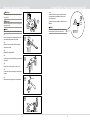
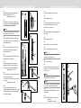
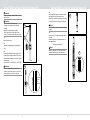
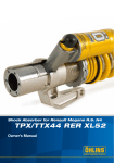
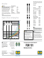
Before installing this product, check the contents
of the kit. If anything is missing, please contact
an Öhlins dealer.
Set-up Data
Warning!
Before riding, always make sure that the
basic settings made by Öhlins are according
to recommended Set-up Data. Read about
adjustments and setting up in the Öhlins
Owner’s Manual before you make any
adjustments. Contact an Öhlins dealer if you
have any questions about setting up the shock
absorber.
Kit Contents
Part No Front fork kit
FGR151 Öhlins Sticker (60x23) white 00191-32
Öhlins Sticker (60x23) blue 00191-33
Shim
00520-32
Spring 10,5N/mm
04744-05
Spring 10N/mm
04744-10
Spring 9,5N/mm
04744-95
Owner’s Manual
07286-01
Recommended set-up
Compression
14 clicks
Rebound
14 clicks
Spring rate
10 N/mm
Spring preload
6 mm
Oil level
160 mm
Fork leg position
Standard position
Öhlins Front Fork Fluid part no 01309-01
Recommended Tools
Cylinder tube holder Ø36 or Soft jaws 28/36 Top cap tool Pull-up tool Seal head tool Seal head tool
Cartridge tool
Fork tube tool Diagram - Oil Level - Air Spring Force
650
Oil level [mm]
600
120
130
550
Air spring for one front fork leg
500
140
150
450
Pcs
1
2
2
2
2
2
2
1
00787-07 00727-09
00797-08 01765-03 01797-07 01797-09
04702-04
00786-05
160
400
Note!
170
Please note that after this installation the
compression adjuster will no longer be useful.
Force [N]
180
350
190
300
200
250
210
200
220
150
100
50
0
0
10
20
30
40
Öhlins products are subject to
continuous improvement and
development, therefore, although
these instructions include the most
up-to-date information available at
the time of printing, minor updates
may occur.
© Öhlins Racing AB. All rights
reserved. Any reprinting or
unauthorized use without the written
permission of Öhlins Racing AB
is prohibited.
50
60
70
Stroke [mm]
80
90
100
110
120
130
Note!
Please note that during storage and
transportation, especially at high ambient
temperature, some of the oil and grease
used for assembling may leak and stain the
packaging. This is in no way detrimental to the
product, wipe off the excessive oil/grease with
a cloth.
Pressurized Front Fork Kit for Yamaha R1
To find the latest information
contact an Öhlins distributor.
Please contact Öhlins if you have
any questions regarding the
contents in this document.
FGR 151
Part no. FGR151_1
Issued 2011-11-03
Öhlins Racing AB
Box 722
S-194 27 Upplands Väsby, Sweden
Phone +46 8 590 025 00
fax +46 8 590 025 80
Warning!
This kit should only be installed by an
authorized Öhlins dealer. The installation
procedure requires certain tools. Before installing this product, read this
document and the Owner’s Manual. The
front fork is an important part of your vehicle
and will affect the stability.
Mounting Instructions
www.ohlins.com
Remove Original Front Fork
Install Öhlins Front Fork Cartridge Kit
Warning!
It is advisable to have an Öhlins dealer install
the front fork.
Warning!
1.2
Make sure the vehicle is securely supported so
that it will not tip.
Note!
1.1
When installing, read Vehicle Service Manual.
1.1
Put the motorcycle on a workstand so that the
front wheel barely touches the ground.
3.13
Install the front fork legs into the triple clamps
at the position recommended in set-up data
(Fork leg position).
Tightening torque according to Vehicle Service
Manual.
Fork leg
position
Note!
Measure the fork leg position from the upper
triple clamp to the top of the outer tube.
1.3
1.2
Remove the front fender, the brake calipers
and the front wheel.
1.3
Release the spring preload.
1.4
Loosen the upper fork triple clamp by loosening
the screws.
1.4
1.5
Loosen (do not remove) the top cap ½ turn.
Screw
1.6
Loosen the lower triple clamp by loosening the
screws.
1.7
Remove the front fork legs from the triple clamp.
1.5
1/2 turn
1.7
1
6
Install Öhlins Front Fork Cartridge Kit
3.5
Tighten the seal head to the cylinder tube
extension using tool 01797-07.
Tightening torque 20 Nm
3.5
Disassemble Original Front Fork
2.1
Loosen the top cap from the outer tube.
3.6
2.2
Pull down the outer tube.
3.6
Pour Öhlins Front Fork fuid into the fork leg
and set the oil level. See set-up data and oil
level-force diagram in this folder.
XXX mm
Note!
2.3
Use appropriate tool according to your vehicle
service manual. Remove the top cap by
loosening it from the shaft.
2.4
Remove the spring and surrounding parts from
the fork leg.
Pour the oil slowly and make sure that there
are no bubbles in the fork leg.
3.7
Put the preload tube and the spring on top of
the cartridge. See set-up data in this folder for
the available springs.
3.7
2.5
Drain the fork leg from oil.
Spring
3.8
3.8
Fasten tool 01765-03 at the top of the shaft
extensioner. Install the spring support by
leading it over the tool.
Spring
support
2.6
Use tool 04702-04. Loosen the cartridge.
2.7
Remove the cartridge from the fork leg.
Preload
tube
3.9
Pull up the shaft assembly and grab the spring
support with a 19 mm wrench.
Note!
If the cylinder tube does not follow with the
cartridge kit, follow these steps:
2.8
Remove the outer tube
3.10
Open the compression and the rebound
adjuster fully. Remove the pull-up tool and
install the top cap to the shaft extensioner. Tightening torque 15 Nm
3.9
3.11
Pull up the outer tube. Make sure the fork leg is
in a fully extended position.
Use tool 00797‑08 to tighten the top cap to the
outer tube.
Tightening torque 10 Nm
Spring
support
2.9
Install tool 00786-05 (Ø43) on the steel tube,
above the holes. Loosen the steel tube from
the fork bottom.
2.8
Note!
Use a heat gun to soften the Loctite between
the steel tube and the fork bottom.
3.10
3.12
Set the spring preload, rebound and
compression adjusters according to set-up data
in this manual. Read more about adjustments
in the Owner’s Manual.
3.11
Note!
Do not remove tool 00786-05 from the steel tube
yet. You will need it to reinstall the stel tube.
2.10
Use appropriate tool (Ø34) and remove the
cylinder tube.
2.11
Use tool 00786-05. Reinstall the steel tube.
Loctite 2701
Tightening torque 130Nm
5
2
2.9
Install Öhlins Front Fork Cartridge Kit
Install Öhlins Front Fork Cartridge Kit
3.4
Use a small dab of grease to attach the shim
(provided in this kit) to the bottom of the
adaptor. This to avoid the cartridge unit seizing
in the fork bottom and making removal easier.
Caution!
Do not mix the parts. Work with only one fork
leg at a time.
Caution!
The front fork kit is divided into one
compression cartridge and one rebound
cartridge.
Make sure to install cartridge marked; “Reb” (Rebound) in the right side fork leg. “Comp” (Compression) in the left side fork leg.
Note!
3.1
When mounting, make sure that the shim stays
in place.
3.5
Use tool 01797-09. Install the cartridge into the
front fork.
Smear moly-grease or equivalent grease on
the adaptor thread.
Tightening torque 30Nm
3.2
3.1
Remove the top cap.
3.4
3.2
Remove the spring support and the preload
tube.
Note!
Make sure that tool 01797-09 grips both the
seal head and the cylinder tube extension.
3.3
Loosen the seal head from the cylinder tube
extension just enough to align the grooves on
the seal head with the grooves on the cylinder
tube extension.
Use tool 01797-07 and 00787-07 or 00727-09.
Caution!
3.5
3.3
Do not loosen the seal head more than is
necessary to align the grooves. If you loosen
the seal head too much the oil may leak.
seal head
cylinder
tube
extension
3
4